

2
Table of Contents
Installation inst r uct i ons
9 Safety Definitions 2
IMPORTANT SAFETY INSTRUCTIONS 3
Electric Safety 3
Appliance Handling Safety 4
Safety Codes and Standards 5
Related Equipment Safety 5
Proposition 65 Warning 5
Before you begin 6
Tools and parts needed 6
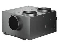
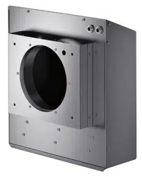
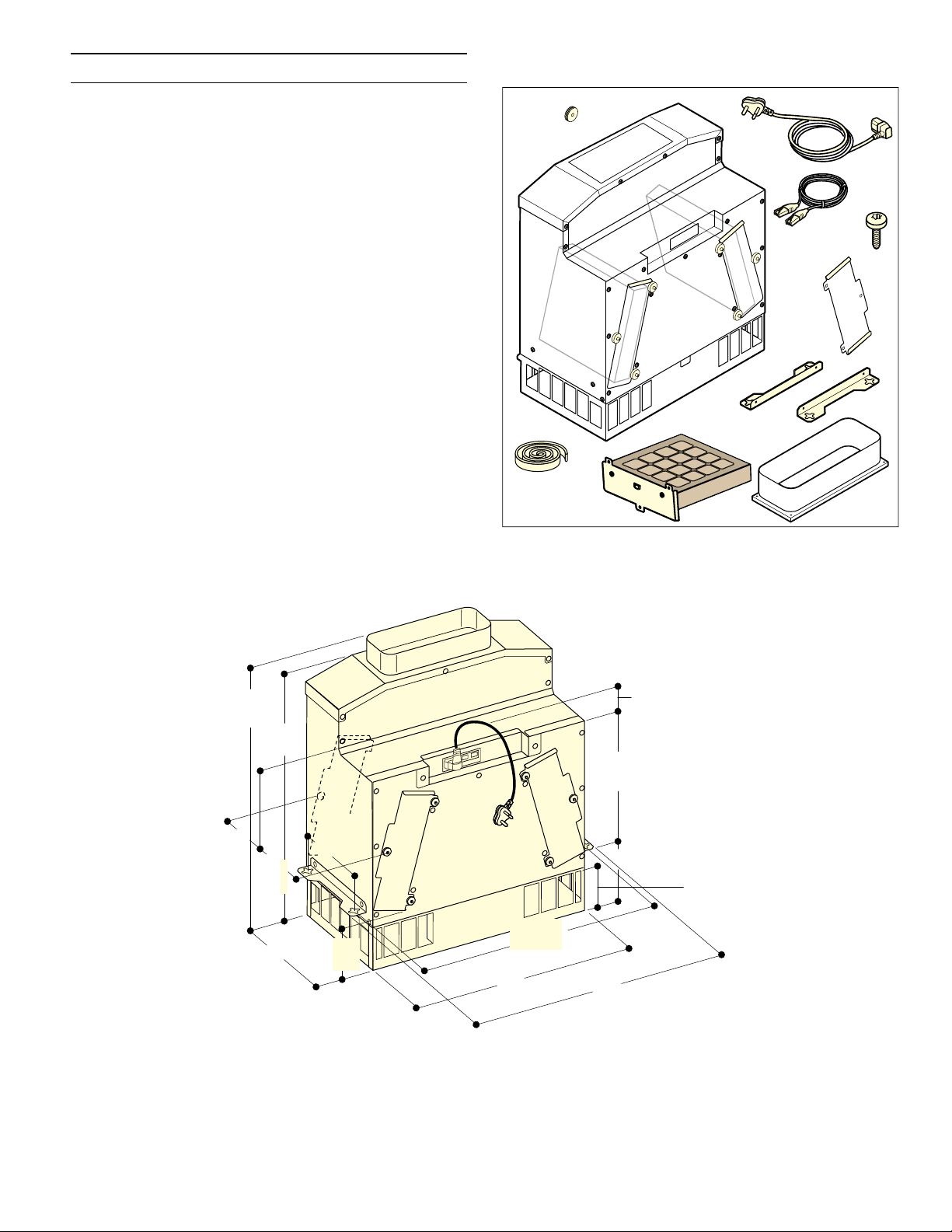
Parts included 6
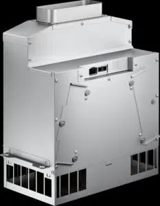
Appliance dimensions 6
Preparing Kitchen Units 8
Preparing the appliance for installation 8
Installation 9
Installing the appliance 9
Connect appliance 11
Networked operation 11
Removing the appliance 11
Regenerating the activated charcoal filter 12
Customer Service 13
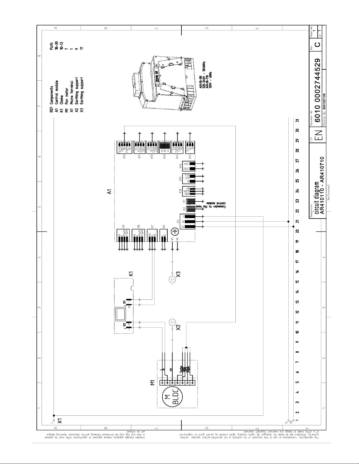
The wiring diagram is available on the last page
of this manual.
Additional information on products, accessories,
replacement parts and services can be found at
www.gaggenau.com and in the online shop
www.gaggenau.com/zz/store
9 Safety Definitions
Saf ety Defi nitions
9 WARNING
This indicates that death or serious injuries may
occur as a result of non-observance of this
warning.
9 CAUTION
This indicates that minor or moderate injuries may
occur as a result of non-observance of this
warning.
NOTICE: This indicates that damage to the appliance
or property may occur as a result of non-compliance
with this advisory.
Note: This alerts you to important information and/or
tips.
3
9 IMPORTANT SAFETY INSTRUCTIONS
READ AND SAVE THESE INSTRUCTIONS
IMPORTANT SAF ET Y INSTRUCTIONS
READ AND SAVE THESE INSTRUCTI ONS
INSTALLER: LEAVE THESE INSTRUCTIONS WITH
THE APPLIANCE AFTER INSTALLATION IS
COMPLETE.
IMPORTANT: SAVE THESE INSTRUCTIONS FOR THE
LOCAL ELECTRICAL INSPECTOR'S USE.
Examine the appliance after unpacking it. In the event of
transport damage, do not plug it in.
WARNING
If the information in this manual is not followed exactly,
fire or shock may result causing property damage or
personal injury.
WARNING
Do not repair, replace or remove any part of the
appliance unless specifically recommended in the
manuals. Improper installation, service or maintenance
can cause injury or property damage. Refer to this
manual for guidance. All other servicing should be done
by an authorized servicer.
WARNING
WARNING – TO REDUCE THE RISK OF FIRE,
ELECTRIC SHOCK, OR INJURY TO PERSONS,
OBSERVE THE FOLLOWING:
‒ Installation work and electrical wiring must be done
by qualified person(s) in accordance with all
applicable codes and standards, including fire-
rated construction.
‒ Sufficient air is needed for proper combustion and
exhausting of gases through the flue (chimney) of
fuel burning equipment to prevent back drafting.
Follow the heating equipment manufacturer’s
guideline and safety standards such as those
published by the National Fire Protection
Association (NFPA), and the American Society for
Heating, Refrigeration and Air Conditioning
Engineers (ASHRAE), and the local code
authorities.
‒ When cutting or drilling into wall or ceiling, do not
damage electrical wiring and other hidden utilities.
‒ Ducted fans must always be vented to the outdoors.
WARNING
The applicable regulations of the energy supply
companies and the regional construction regulations
must be observed when installing the hood.
WARNING
Risk of fire
Operating several gas burners at the same time gives
rise to a great deal of heat. The ventilation appliance
may become damaged or catch fire. The ventilation
appliance must only be combined with gas burners that
do not exceed the maximum total output of 61,000 BTU/
hr (18 kW). If 41,000 BTU/hr (12 kW) is exceeded, the
local regulations concerning room ventilation, room
size, and combination with ventilation devices in exhaust
and recirculating operation must be followed.
WARNING
To reduce the risk of fire, use only metal ductwork.
CAUTION
For general ventilating use only. Do not use to exhaust
hazardous or explosive materials and vapors.
This appliance is intended for normal family household
use only. It is not approved for outdoor use. See the
Statement of Limited Product Warranty. If you have any
questions, contact the manufacturer.
Electric Safety
WARNING
GROUNDING INSTRUCTIONS
This appliance must be grounded. In the event of an
electrical short circuit, grounding reduces the risk of
electric shock by providing an escape wire for the
electric current.
This appliance is equipped with a cord having a
grounding wire with a grounding plug. The plug must be
plugged into an outlet that is properly installed and
grounded.
9 IMPORTANT SAFETY INSTRUCTIONS
READ AND SAVE THESE INSTRUCTIONS
4
WARNING
Improper grounding can result in a risk of electric
shock. Consult a qualified electrician if the grounding
instructions are not completely understood, or if doubt
exists as to whether the appliance is properly grounded.
Do not use an extension cord. If the power supply cord
is too short, have a qualified electrician install an outlet
near the appliance.
WARNING
Before you plug in an electrical cord or turn on power
supply, make sure all controls are in the OFF position.
For appliances equipped with a cord and plug, do not
cut or remove the ground prong. It must be plugged into
a matching grounding type receptacle to avoid electrical
shock. If there is any doubt as to whether the wall
receptacle is properly grounded, the customer should
have it checked by a qualified electrician.
If required by the National Electrical Code (or Canadian
Electrical Code), this appliance must be installed on a
separate branch circuit.
WARNING
To reduce the risk of fire or electric shock, do not use
this fan with any solid-state speed control device.
WARNING
Risk of electrical shock or fire
Frame grounded to neutral through a ground strap.
Grounding through the neutral conductor is prohibited
for new branch-circuit installations (1996 NEC), mobile
homes, and recreational vehicles, or in an area where
local codes prohibit grounding through the neutral
conductor.
For installations where grounding through the neutral
conductor is prohibited,
a) disconnect the link from the neutral,
b) use grounding terminal or lead to ground unit,
c) connect neutral terminal to lead branch circuit
neutral in usual manner (when the appliance is to
be connected by means of a cord kit, use a
UL listed 4-conductor cord for this purpose).
Installer – show the owner the location of the circuit
breaker or fuse. Mark it for easy reference.
Before installing, turn power OFF at the service panel.
Lock service panel to prevent power from being turned
ON accidentally.
WARNING
TO REDUCE THE RISK OF FIRE, ELECTRIC SHOCK,
OR INJURY TO PERSONS, OBSERVE THE
FOLLOWING:
‒ Use this unit only in the manner intended by the
manufacturer. If you have questions, contact the
manufacturer.
‒ Before servicing or cleaning unit, switch power off
at service panel and lock the service disconnecting
means to prevent power from being switched on
accidentally.
When the service disconnecting means cannot be
locked, securely fasten a prominent warning device,
such as a tag, to the service panel.
Be sure your appliance is properly installed and
grounded by a qualified technician. Installation,
electrical connections and grounding must comply with
all applicable codes.
WARNING
Risk of electric shock
Parts inside the appliance can have sharp edges. The
connection cable can be damaged. Do not bend or
pinch connection cables during installation.
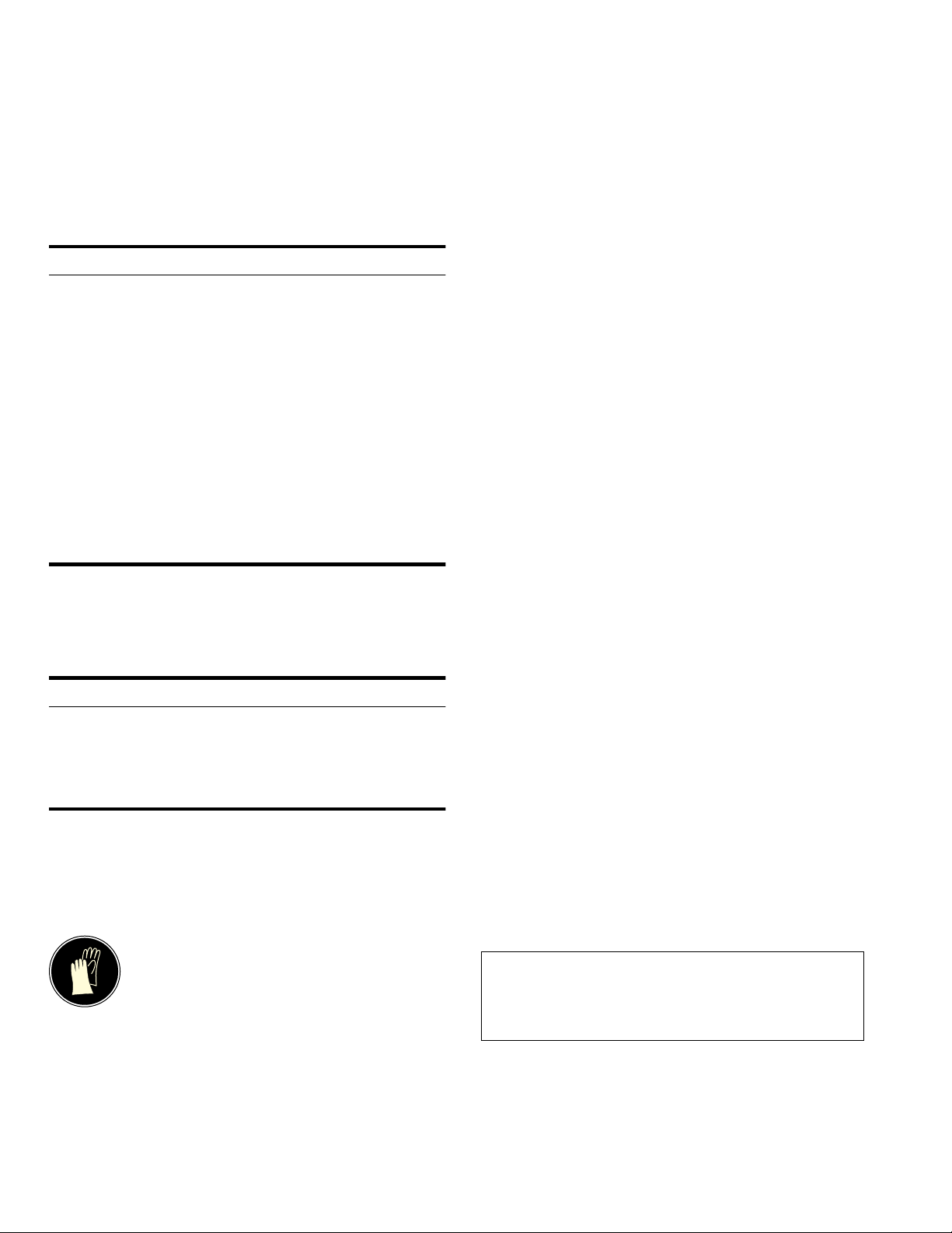
Appliance Handling Safety
Hidden surfaces may have sharp edges.
Use caution when reaching behind or
under appliance.

5
9 IMPORTANT SAFETY INSTRUCTIONS
READ AND SAVE THESE INSTRUCTIONS
Safety Codes and Standards
This appliance complies with the latest version of one or
more of the following standards:
▯ UL 507 - Electric Fans
▯ CAN/CSA C22.2 No. 113 - Fans and Ventilators
It is the responsibility of the installer to determine if
additional requirements and/or standards apply to
specific installations.
Related Equipment Safety
Remove all tape and packaging before using the
appliance. Destroy the packaging after unpacking the
appliance. Never allow children to play with packaging
material.
The appliance should only be used if installed by a
qualified technician in accordance with these
installation instructions. The manufacturer is not
responsible for any damage resulting from incorrect
installation.
Never modify or alter the construction of the appliance.
For example, do not remove leveling legs, panels, wire
covers or anti-tip brackets/screws.
Proposition 65 Warning:
This product may contain a chemical known to the State
of California, which can cause cancer or reproductive
harm. Therefore, the packaging of your product may
bear the following label as required by California:
&DQFHUDQG5HSURGXFWLYH+DUPZZZ3:DUQLQJVFDJRY
67$7(2)&$/,)251,$352326,7,21:$51,1*
:$51,1*
6
Before you begin
Before you begin
Tools and parts needed
▯ Screwdriver Torx T20
▯ Pencil
▯ Drill with ¼" (6 mm) bit
▯ Jigsaw
▯ Tape Measure
Parts included
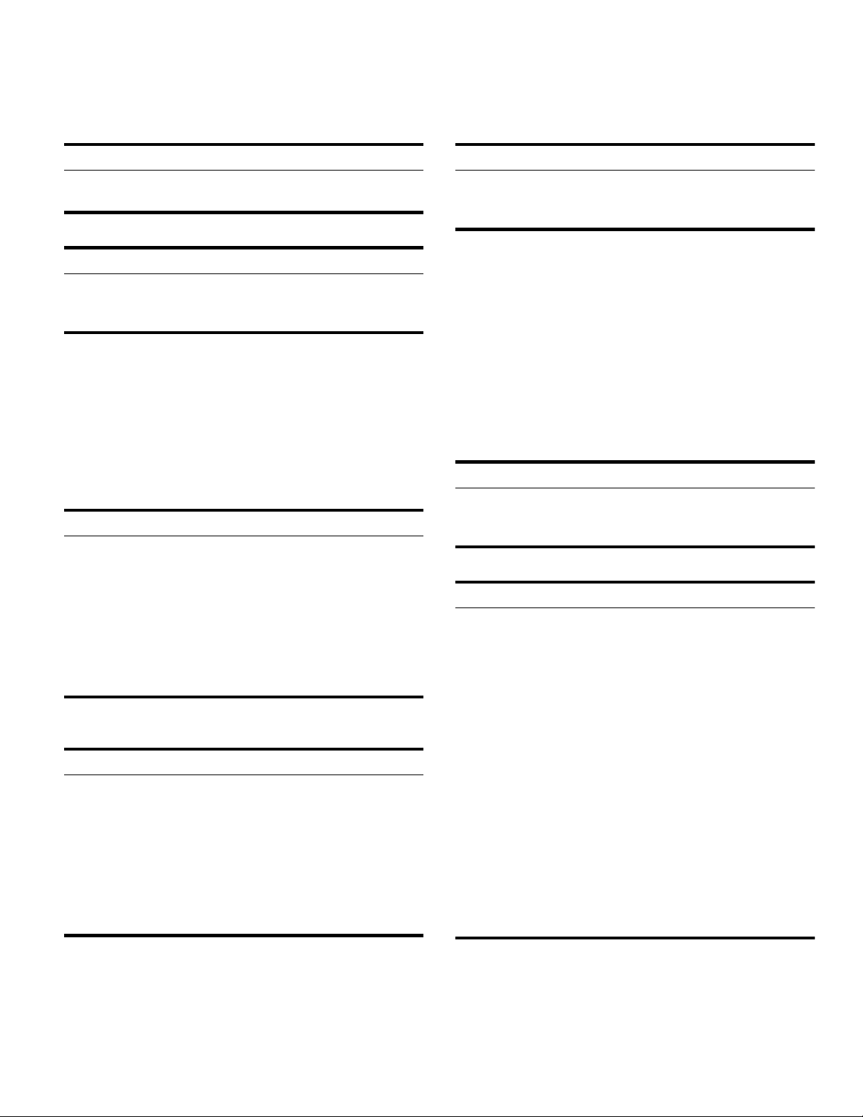
Appliance dimensions
[
[
[
[
ê
ʎ¼ʚ
èʌ¼ʓʘ
èç¼ʓʘ
ʎ¼ʚ
PP
ʌ¼ʓʘ
èʌ¼ʓʘ
è¼ʚ
ʐ¼ʓʘ
ʌ¼ʚ
è¼ʚ

7
Installation examples
PP
;
PLQ
ʐ¼ʓʘ
PLQ
è¼ʚ
ç¼ʚ
PLQ
PLQ
ʐ¼ʓʘ
PLQ
ê
ʎ¼ʚ
è¼ʚ
ç¼ʚ
[
PLQ
é[
[
ʎ¼ʚ[
[
ʌ¼ʚ[
[
è¼ʚ[
PLQ
ë
èʌ¼ʓʘ
ʐ¼ʓʘ
8
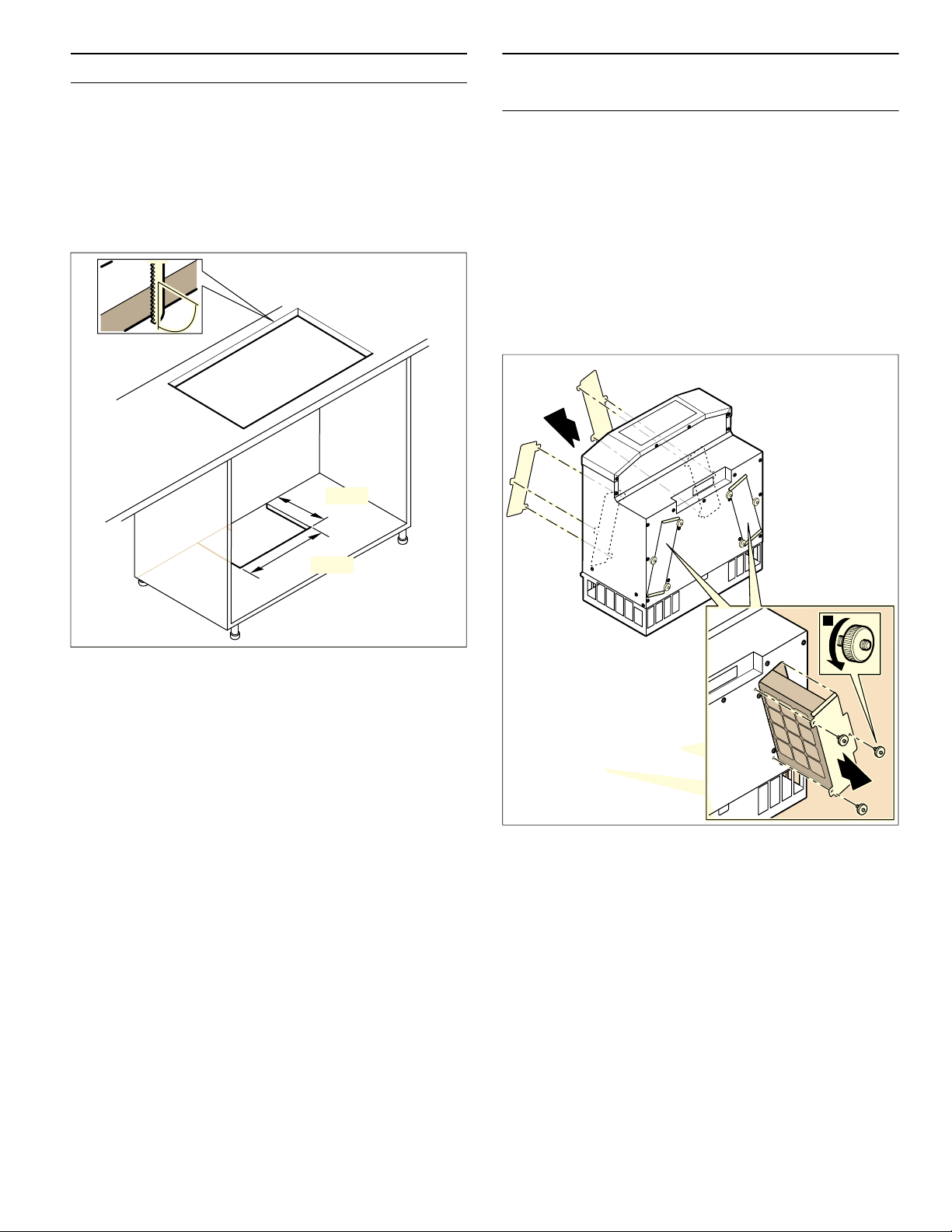
Preparing Kitchen Units
Prepar i ng Kitchen Units
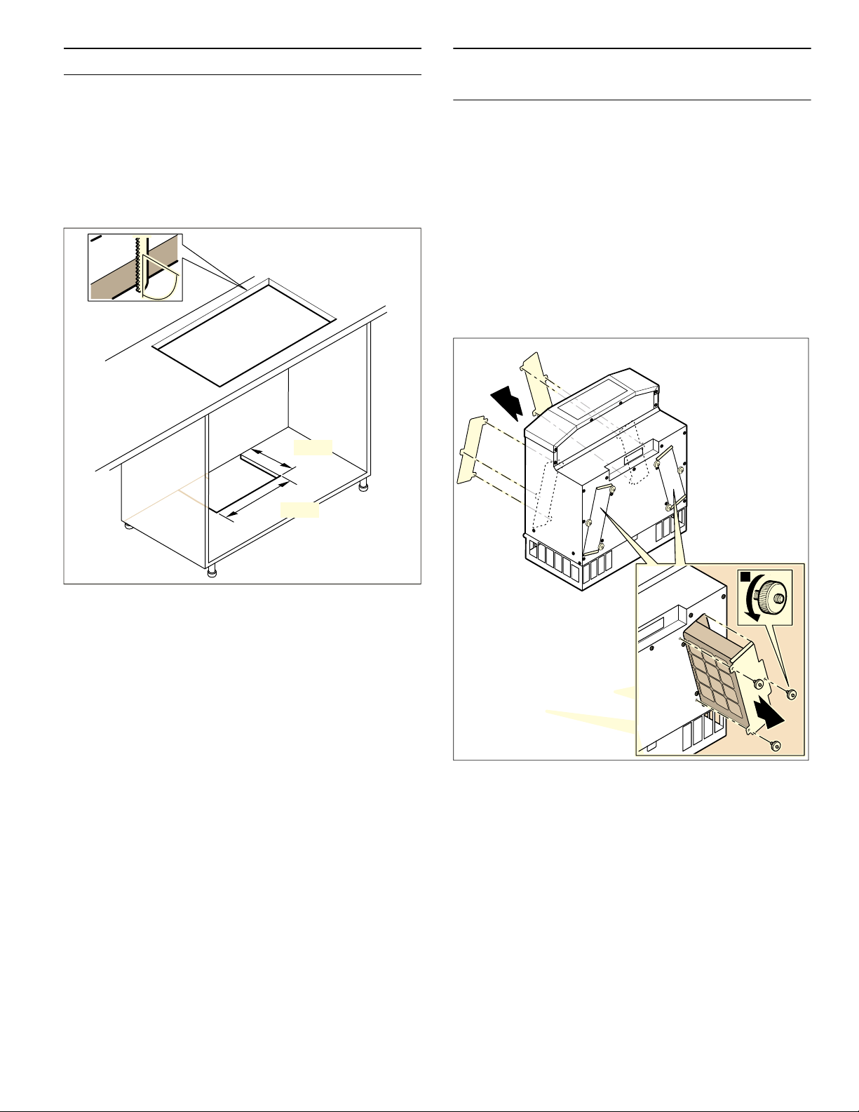
The fitted unit must still be sturdy after the cut-outs have
been made.
Make the cut-out in the base plate as shown in the
installation drawing.
After making the cut-outs, remove any shavings.
Exhaust opening in the cabinet base panel
Provide an air outlet in the cabinet base panel, minimum
cross-section approx. 110 square inches (700 cm²).
Make the exhaust opening in the cabinet base panel as
large as possible in order to keep drafts and noise to a
minimum.
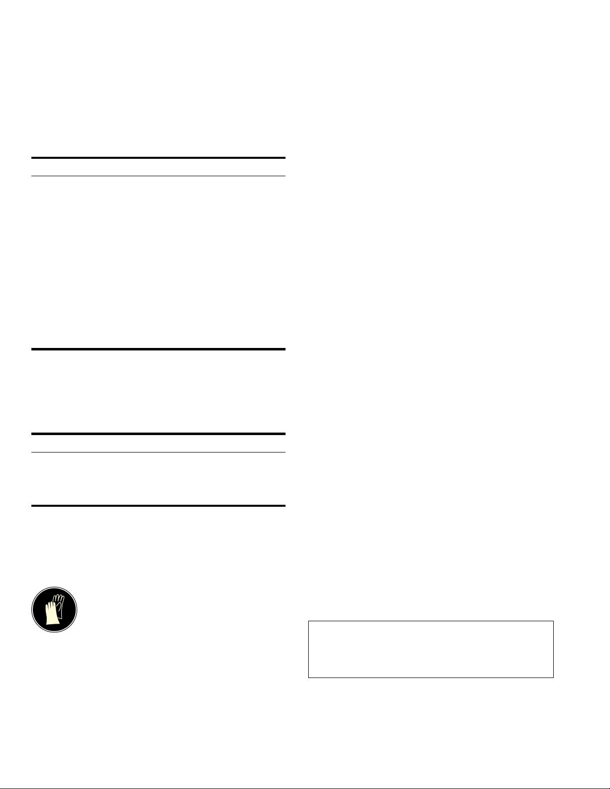
Preparing the appliance for
installation
Prepar i ng the appliance for inst al l at i on
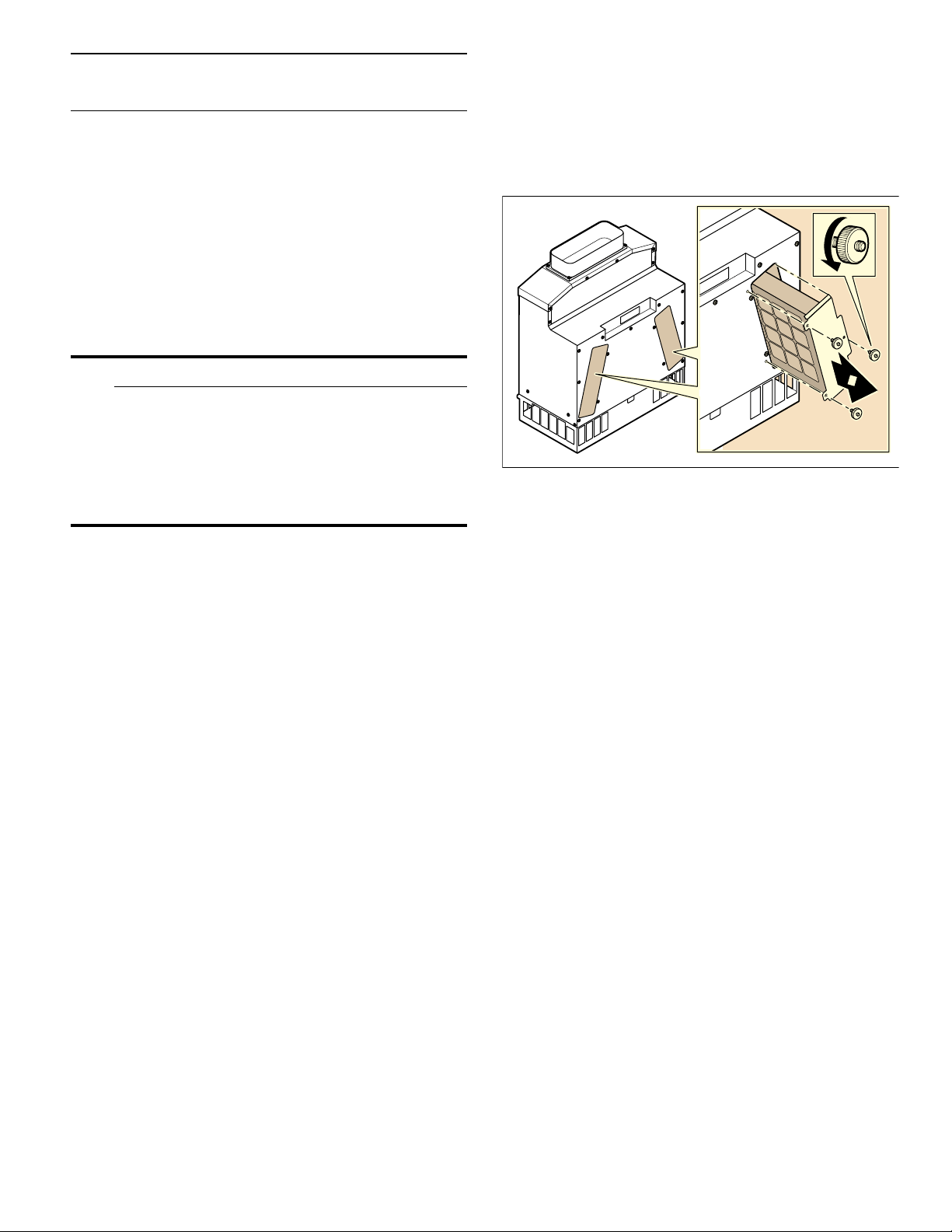
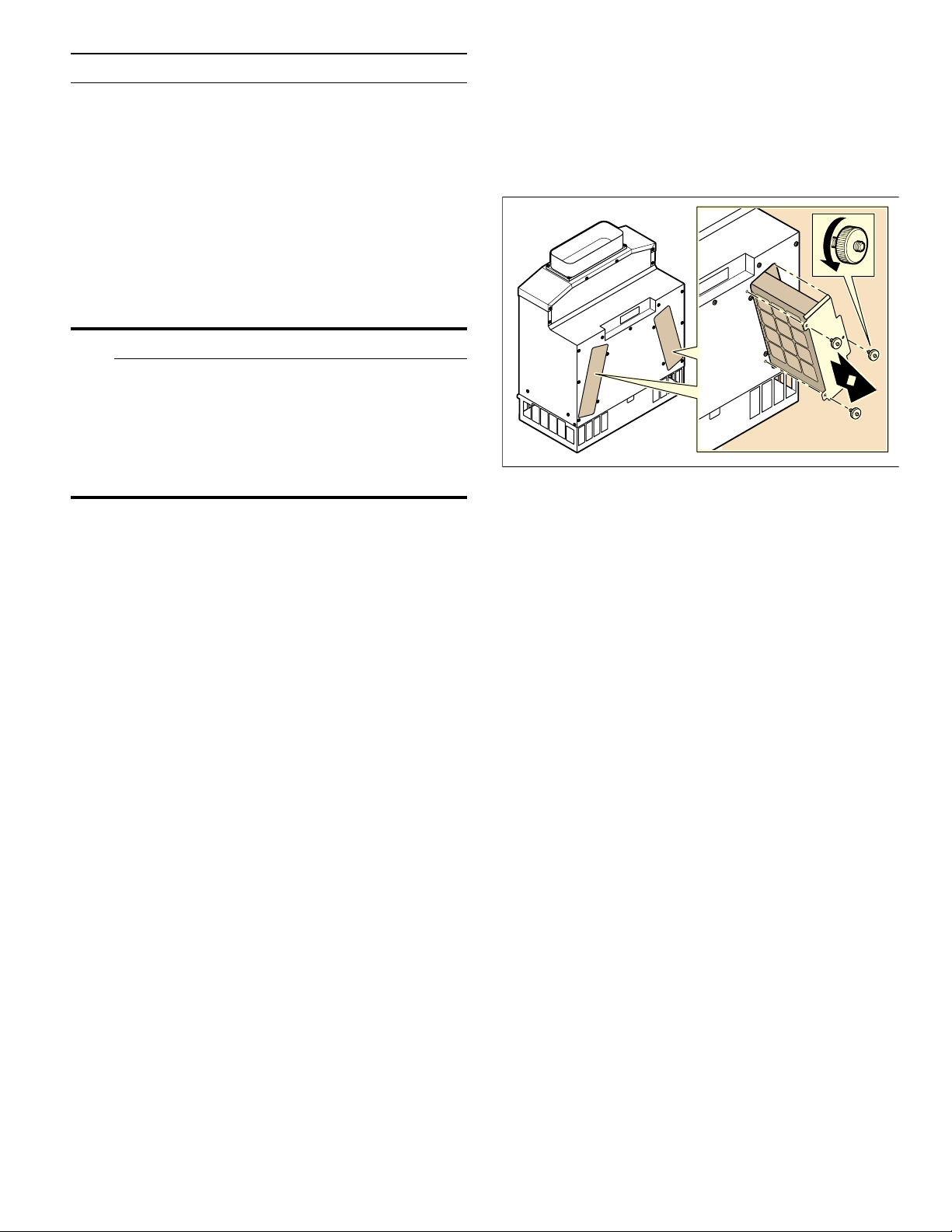
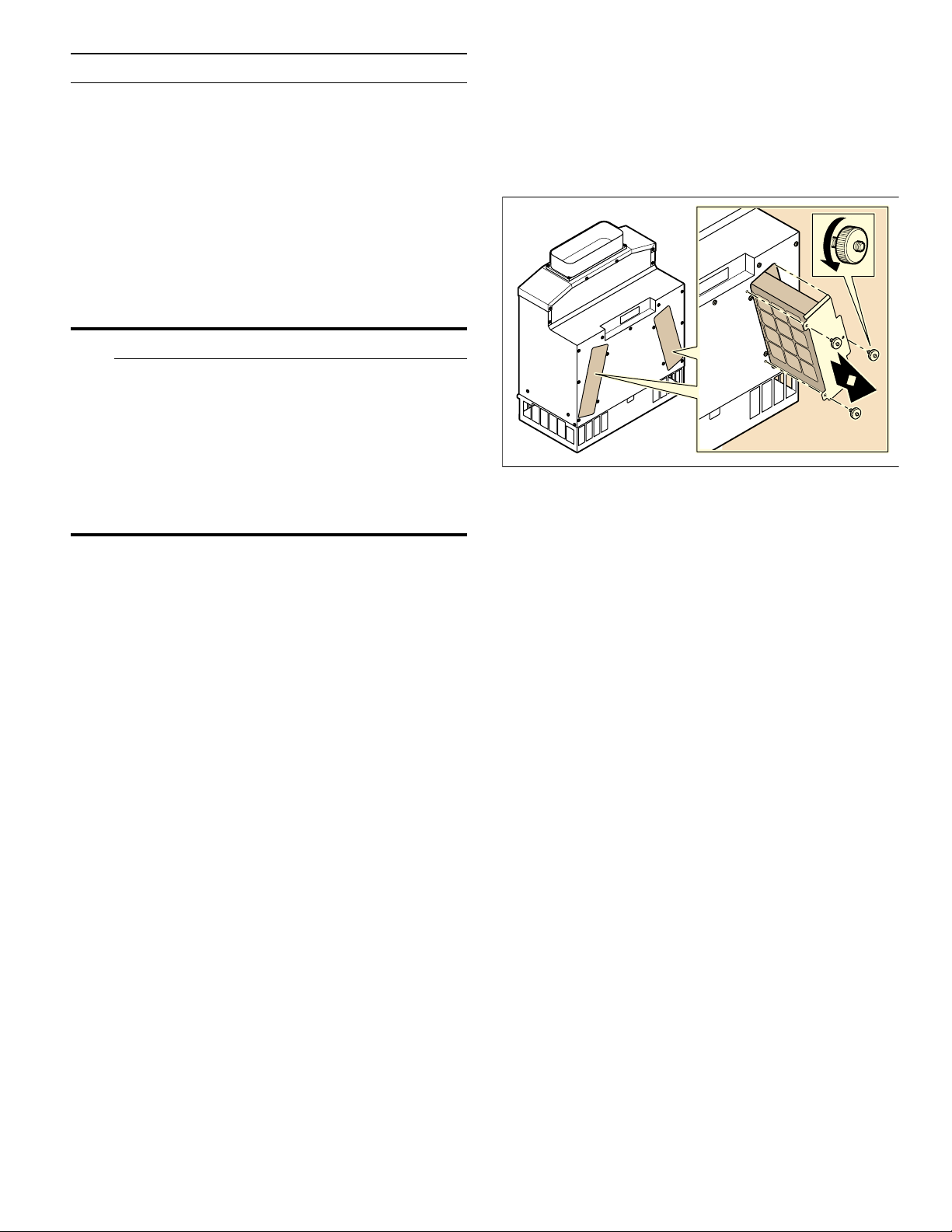
NOTICE: The filters must be removed for cleaning on a
regular basis.
The filters come preinstalled in the appliance and can
only be taken out from one side. If required by the
installation situation, you can fit the filters on the
opposite side so that they are still accessible following
installation.
1 Loosen the screws on the filter covers on both
sides
(A). Remove the filter covers (B).
2 Carefully remove the filters with both hands (C).
NOTICE: The activated charcoal filters are heavy.
Do not drop them – this may cause parts of the filter
to break off.
3 Insert the filter on the opposite side. Secure each
one using three straight-knurled nuts.
4 Use three straight-knurled nuts to secure each filter
cover to the filter openings that are not in use.
PP
é
2
[
$
&
%
9
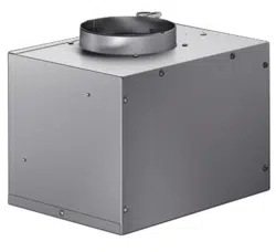
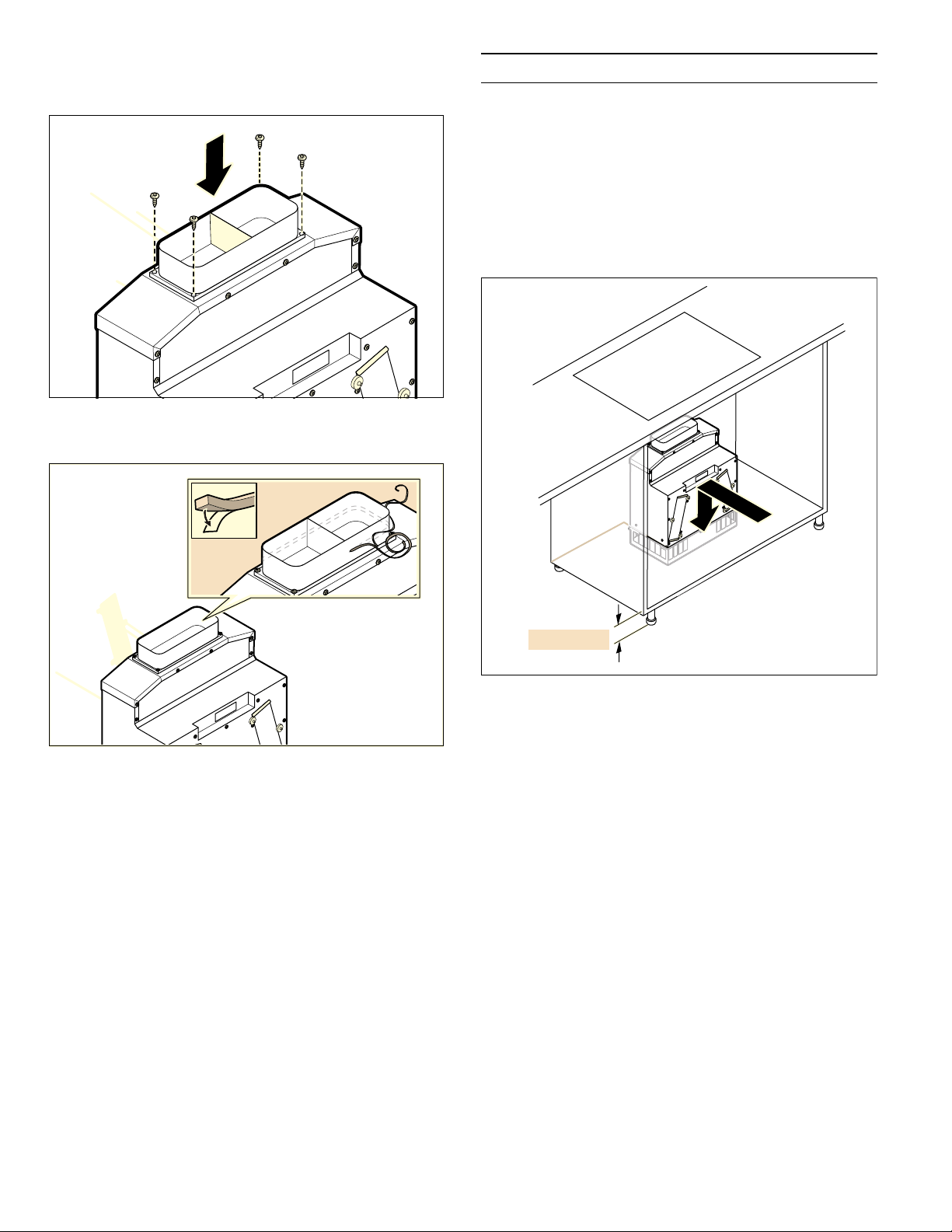
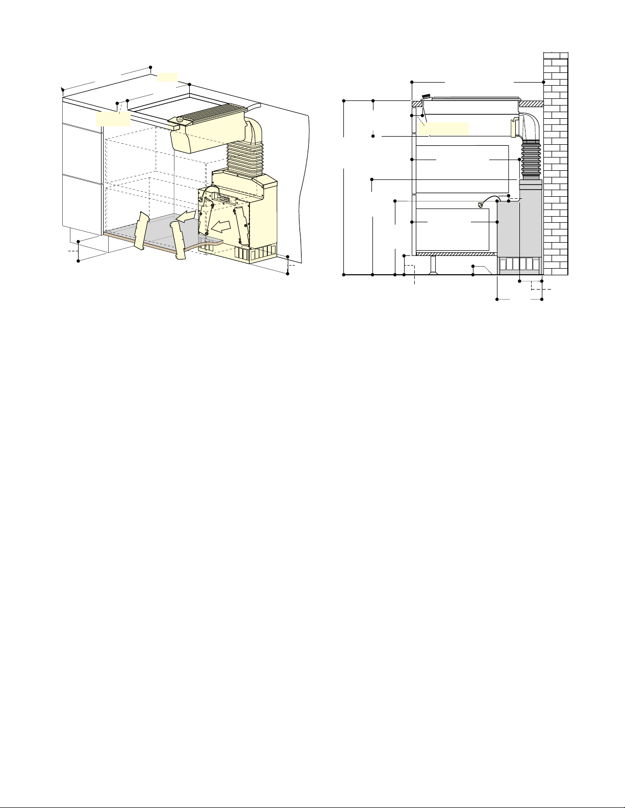
5 Attach the ventilation piece on the upper opening of
the appliance and secure it in place using four
screws.
6 Adhere the sealing strip around the edge of the
ventilation piece.
Installation
Inst al l at i on
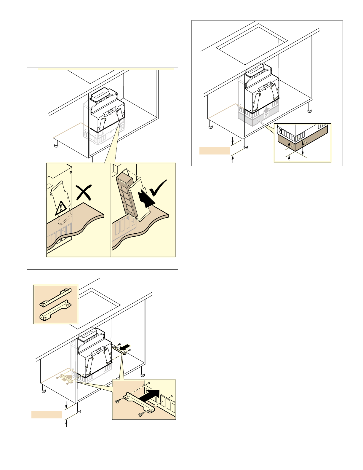
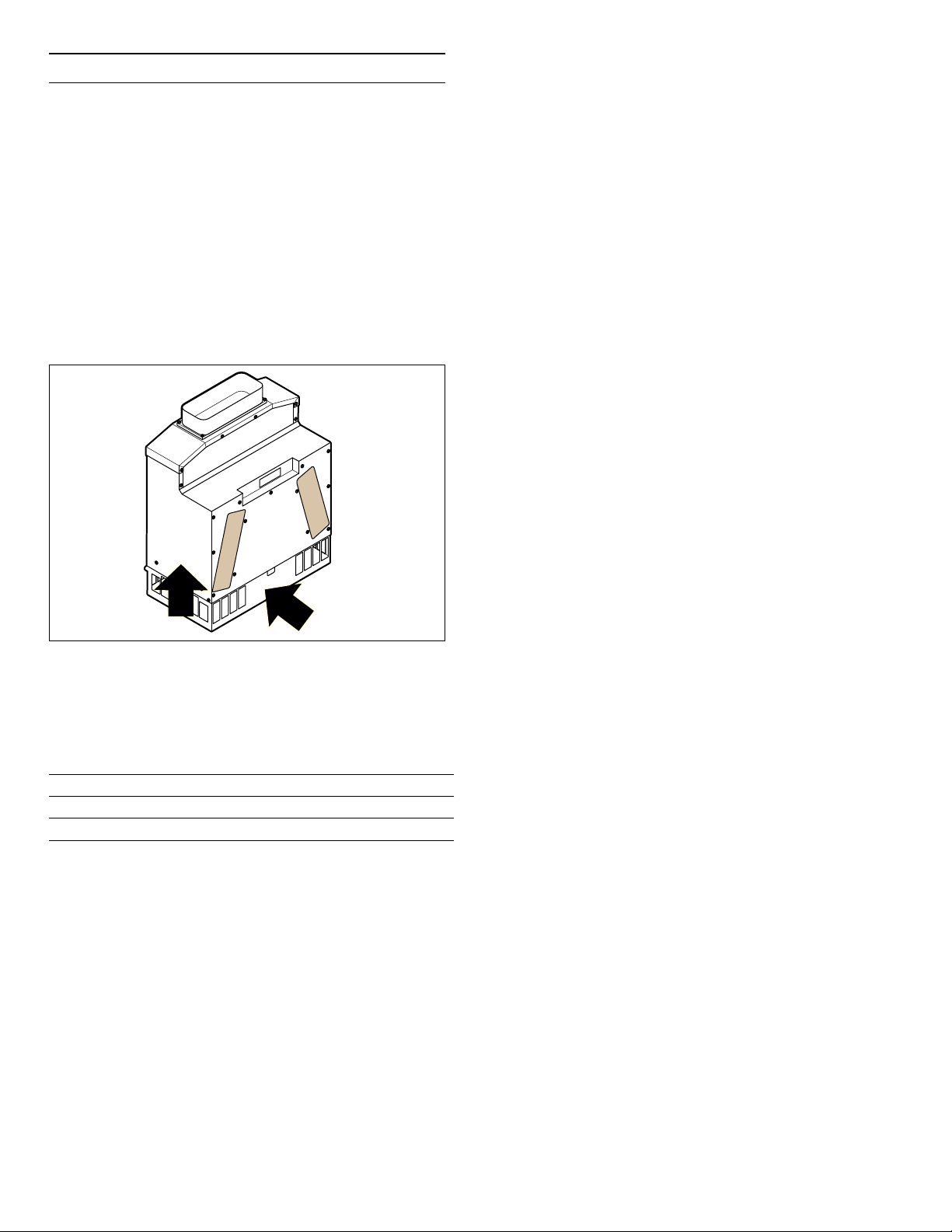
Installing the appliance
1 Insert the appliance into the cut-out.
Do not kink or trap the connection cable, or route it
over sharp edges.
Note: The appliance has rubber feet; it does not
need to be secured in place.
è¼ʚ
PP

10
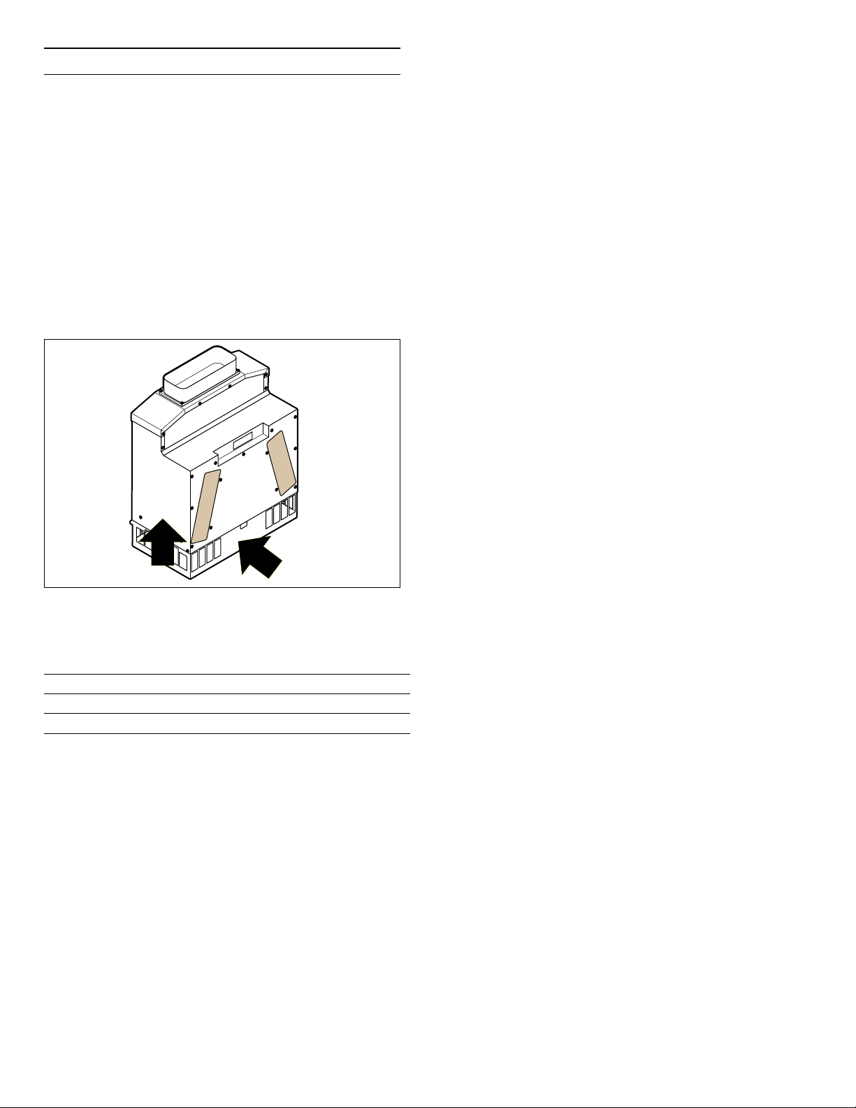
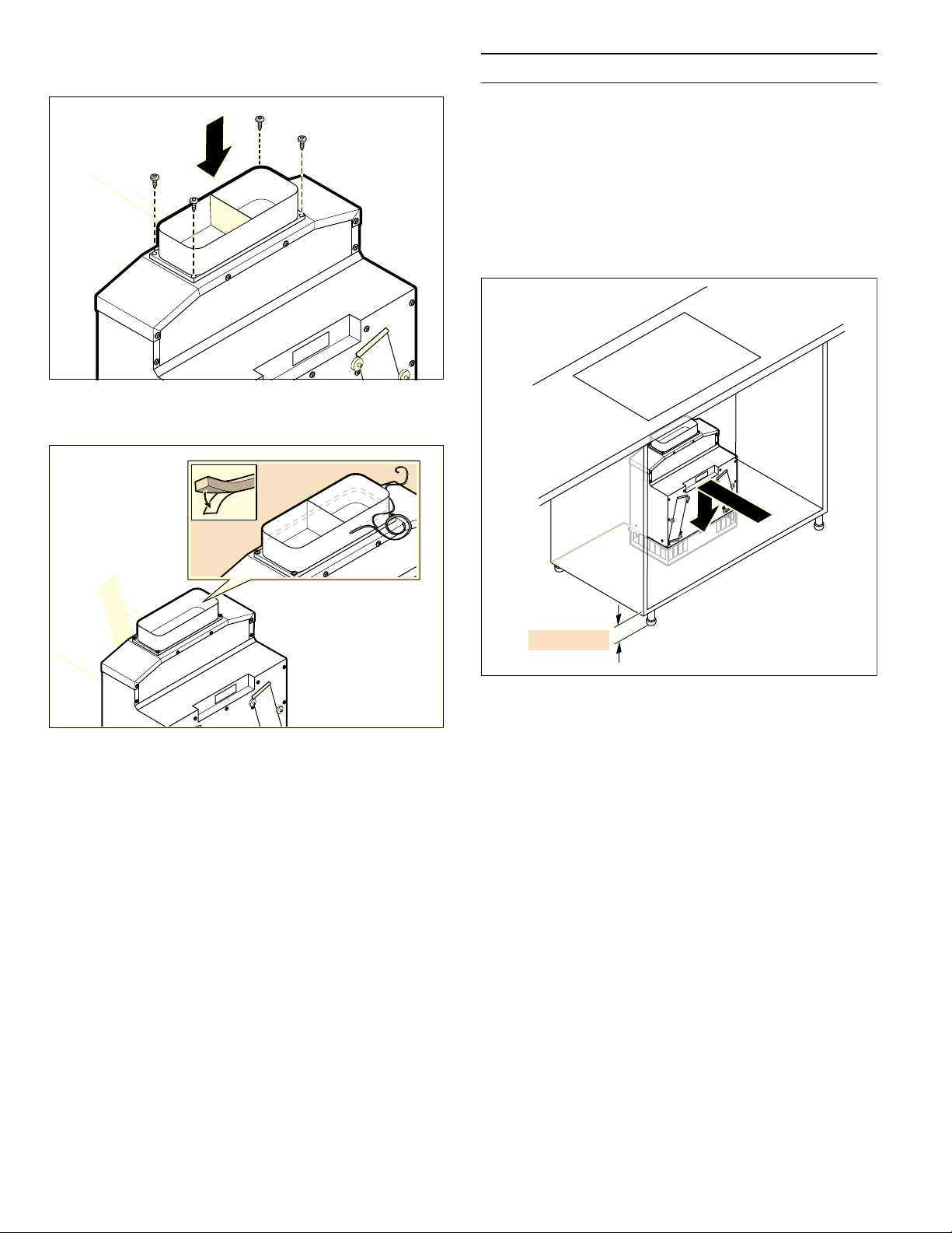
2 Alternative: If the skirting is more than 3
1
/
8
inches
(80 mm) high, attach the enclosed brackets to the
sides of the appliance (A) or support the appliance
from below (B). Otherwise, you may not be able to
access the filters.
Note: Align the appliance horizontally.
3 Fit the connecting piece to the appliance.
4 Lay the piping to the downdraft ventilation and seal
it appropriately.
5 Secure the exhaust pipe to the connecting piece
and seal it appropriately.
!è¼ʚ
PP
$
PP
!
è¼ʚ
è¼ʚ[
[
[
%
11
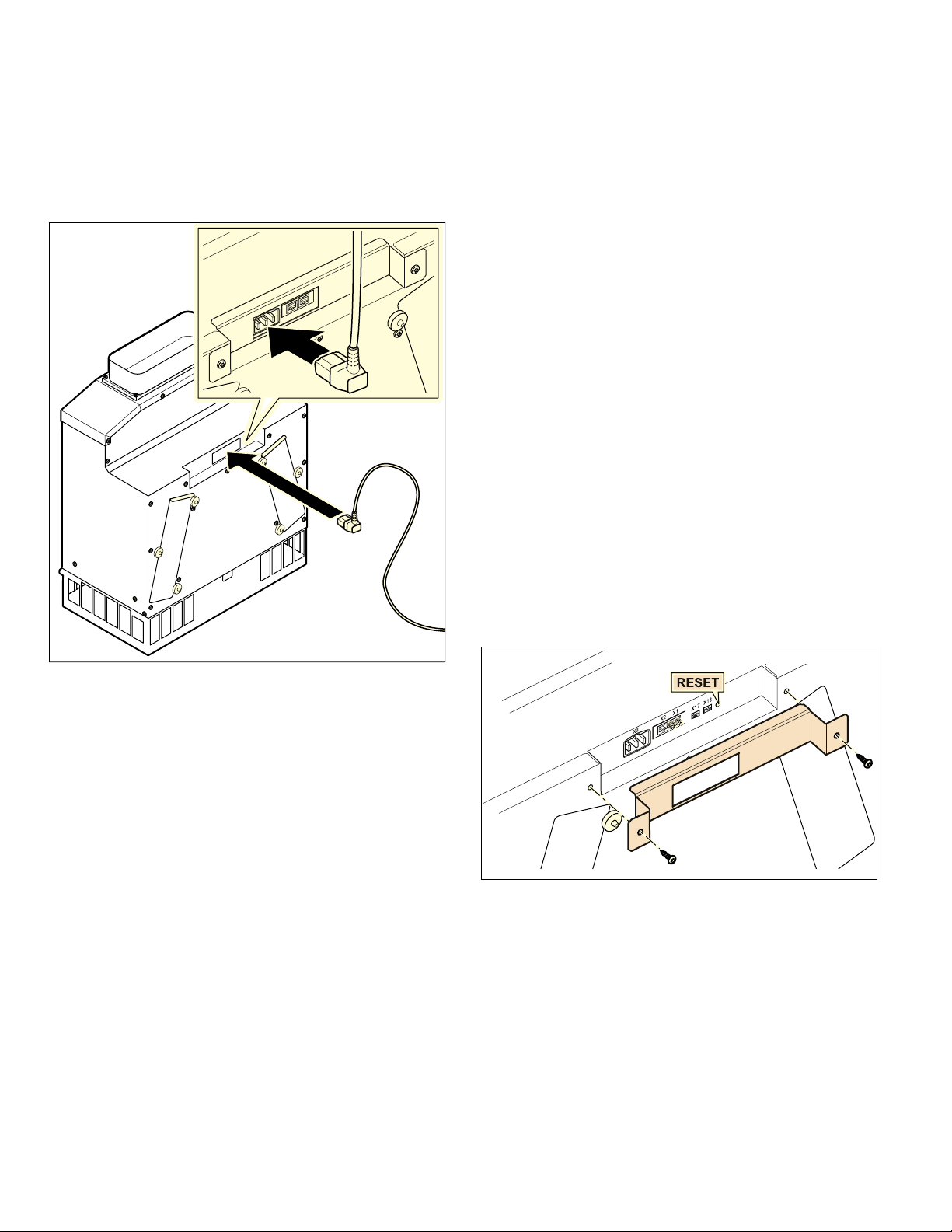
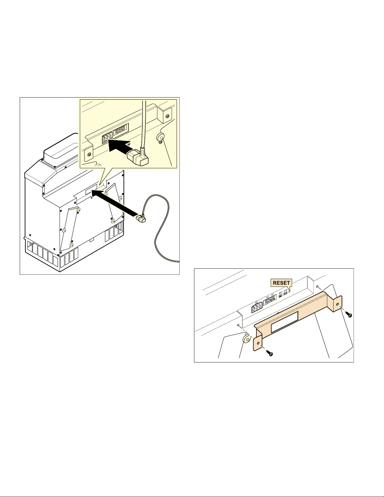
Connect appliance
1 Use the control cable to connect the remote fan unit
and the fan. The plug must snap into place.
2 Plug the remote fan unit's mains plug into the
grounded socket.
Note: Do not kink or trap the connection cable, or
route it over sharp edges.
3 Check that the appliance works. If the appliance
does not work, check that the control cable is
correctly positioned.
Networked operation
Several appliances can be networked together. The light
and blower on each of the appliances are operated
synchronously.
Connect the appliances in series via the connector
sockets X1 and X2 (equal value). The sequence of the
networking does not have any effect. If the enclosed
network cables are too short, use a commercially
available network cable (min. Cat. 5, shielded).
Maximum number of networked appliances: 20. Total
length of all of the network cables: 131 feet (40 m).
During the initial installation, a qualified electrician
must check that the system functions correctly.
If one of the networked appliances fails (power
interruption, network cable disconnected), this leads to
the blower function being blocked for the entire system.
All of the buttons on the appliance flash.
When changing the configuration, the system must be
re-initialized:
1 Unscrew the cover plate.
2 Press and hold the reset button until both LEDs
light up continuously (approx. 5 seconds). Then
release the button within 5 seconds.
3 Screw on the cover plate.
4 After initialization, have a qualified electrician
check that the system functions correctly.
Removing the appliance
Disconnect the appliance from the power supply.
Remove the control cable. Undo the exhaust
connections. Pull out the appliance.
12
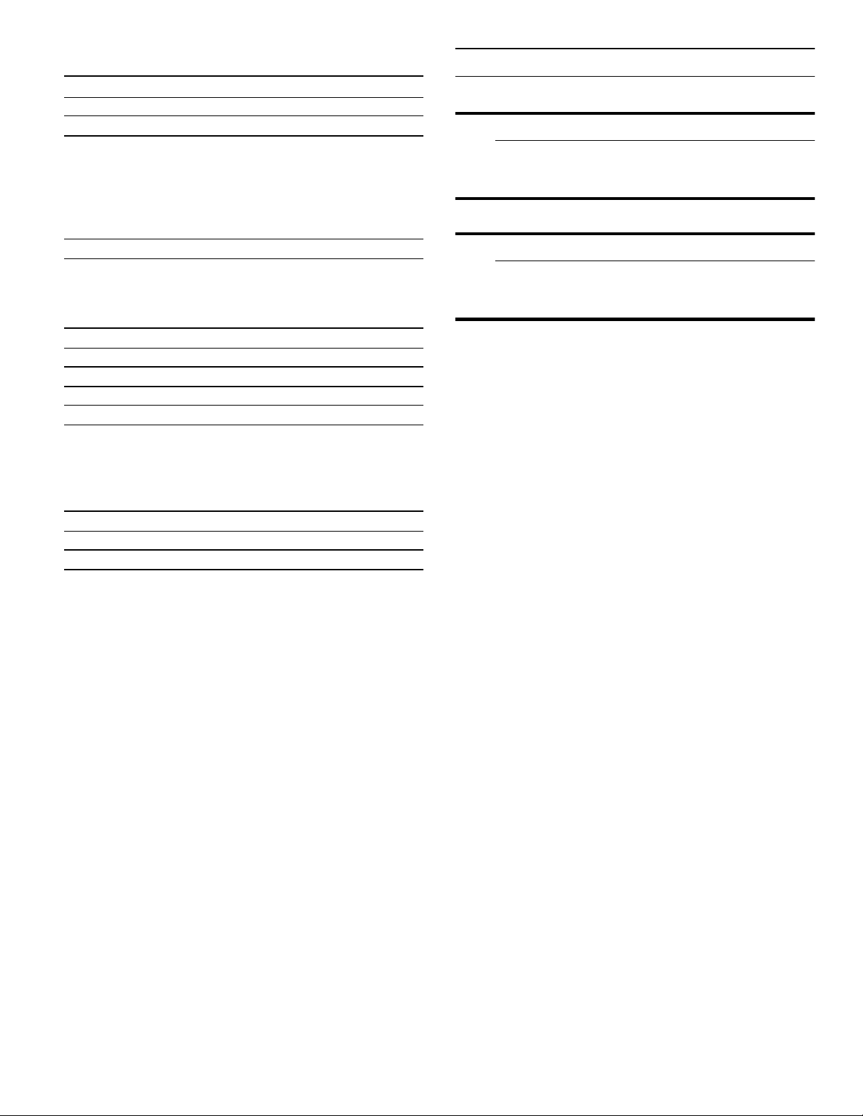
Regenerating the activated charcoal
filter
With normal use (daily for approx. 1 hour), the filters
must be regenerated every 3-4 months in order to
ensure that odors continue to be eliminated effectively.
Note: The activated charcoal filters can be regenerated
up to 30 times and must be replaced at least once every
10 years.
Note: With normal use (daily for approx. 1 hour), the
activated charcoal filters must be replaced at least every
10 years.
9 WARNING
Risk of burns
The activated charcoal filter remains hot for quite
some time after it has been regenerated. Do not
touch the activated charcoal filter straight after it
has been regenerated – allow it to cool down.
Leave the hot activated charcoal filter to cool
down on a heat-resistant surface.
NOTICE:
▯ The activated charcoal filters are fragile and heavy.
Always hold the activated charcoal filters with both
hands.
▯ The activated charcoal filter remains hot for quite
some time after it has been regenerated. Do not
place the activated charcoal filter directly onto an
easily damaged surface straight after it has been
regenerated – allow it to cool down sufficiently first.
▯ To regenerate the activated charcoal filter, place it
on a wire rack as baking trays may be scratched.
▯ Never clean activated charcoal filters with cleaning
products, water, in the dishwasher or with a damp
cloth.
▯ Do not regenerate activated charcoal filters using
the pyrolytic self-cleaning function or significantly
above 390° F (200 °C).
1 Undo the straight-knurled nuts on the two filter
covers.
2 Carefully remove the activated charcoal filter with
both hands.
NOTICE: The activated charcoal filter is heavy. Do
not drop it – this may cause parts of the filter to
break off.
3 Heat the activated charcoal filter in an oven heated
to 390° F (200 °C) for 120 minutes in air
recirculation mode.
4 Allow the activated charcoal filter to cool down.
5 Carefully insert the regenerated activated charcoal
filter with both hands.
6 Secure each activated charcoal filter in place with
three straight-knurled nuts.
2
[
1
2
13
Customer Service
If your appliance needs repairs, our customer service is
there for you. We work hard to help solve problems
quickly and without unnecessary service calls, getting
your appliance back up and running correctly in the
least amount of time possible.
When you call, please indicate the product number
(E-Nr.) and serial number (FD-Nr.) so that we can
support you in a qualified manner.
You will find the type plate with these numbers at the
front and side of the appliance.
To avoid having to search for a long time when you need
it, you can enter your appliance data and the customer
support telephone number here.
Please read the Instruction Manuals provided with your
appliance. Failure to do so may result in an error in
using the appliance. This could result in a service call
that instead of fixing a mechanical issue is only needed
for customer education. Such calls are not covered by
the appliance warranty.
Please find the contact data of all countries in the
enclosed customer service list.
To book a service visit and product advice
E-Nr. FD-Nr.
Customer Service
O
USA 877 442 4436
toll-free
CANADA 877 442 4436
toll-free

14
Table des matières
Noti ce de montage
9 Définitions de sécurité 14
CONSIGNES DE SÉCURITÉ IMPORTANTES 15
Sécurité électrique 16
Sécurité de manutention des appareils 17
Codes et normes de sécurité 17
Équipement de sécurité 17
Avertissement issu de la proposition 65 17
Avant de commencer 18
Outils et pièces nécessaires 18
Pièces comprises 18
Cotes de l'appareil 18
Préparation des meubles 20
Préparation de l’appareil pour l’encastrement 20
Installation 21
Encastrement de l'appareil 21
Brancher l’appareil 23
Utilisation en réseau 23
Dépose de l'appareil 23
Régénération du filtre à charbon actif 24
Service après-vente 25
Le schéma de câblage se trouve à la dernière
page de ce manuel d’installation.
Vous trouverez des informations supplémentaires
concernant les produits, accessoires, pièces de
rechange et services sur Internet sous :
www.gaggenau.com et la boutique en ligne :
www.gaggenau.com/zz/store
9 Définitions de sécurité
Défi nitions de sécurit é
9 AVERTISSEMENT
Ceci indique que le non-respect de cet
avertissement peut entraîner des blessures
graves, voire la mort.
9 ATTENTION
Ceci indique que le non-respect de cet
avertissement peut entraîner des blessures
légères ou de gravité moyenne.
AVIS : Ceci indique que la non-conformité à cet avis de
sécurité peut entraîner des dégâts matériels ou
endommager l'appareil.
Remarque : Ceci vous signale des informations et/ou
indications importantes.

15
9 CONSIGNES DE SÉCURITÉ IMPORTANTES
LIRE ET CONSERVER CES INSTRUCTIONS
CONS I GNE S DE SÉCURI T É IMPORTANTES
LI RE ET CONSERVER CES INSTRUCTI ONS
INSTALLATEUR : LAISSEZ CES INSTRUCTIONS AVEC
L'APPAREIL APRÈS UNE FOIS L'INSTALLATION
TERMINÉE.
IMPORTANT : CONSERVER CES INSTRUCTIONS
POUR L'USAGE DE L'INSPECTEUR ÉLECTRIQUE
LOCAL.
Contrôler l'appareil après l'avoir déballé. Si l'appareil a
été endommagé durant le transport, ne pas le brancher.
AVERTISSEMENT
Si l’information de ce guide n’est pas suivie exactement,
il peut en résulter un incendie ou un choc électrique
causant des dommages à la propriété, des blessures ou
la mort.
AVERTISSEMENT
Ne réparez, remplacez, ni ne retirez aucune partie de
l'appareil, excepté si les manuels recommandent de le
faire. Une installation, un entretien ou une inspection
incorrects peuvent occasionner des blessures ou des
dommages matériels. Reportez-vous au présent manuel
pour obtenir des indications. Toute autre intervention
doit être effectuée par un technicien agréé.
AVERTISSEMENT
ATTENTION – AFIN DE RÉDUIRE LES RISQUES
D’INCENDIE, DE CHOC ÉLECTRIQUE OU DE
BLESSURES CORPORELLES, VEUILLEZ SUIVRE LES
INSTRUCTIONS SUIVANTES :
‒ Les travaux d’installation et de raccordement
électrique doivent être effectués par une personne
qualifiée, conformément aux codes et standards de
construction, y compris ceux concernant le feu.
‒ Assurez-vous que l'aération est suffisante pour
permettre la combustion et l'évacuation des gaz par
le conduit de cheminée d'un appareil à combustible
afin de prévenir le refoulement d'air. Respectez les
instructions du fabricant de l'appareil de chauffage
et les normes de sécurité, comme celles publiées
par la National Fire Protection Association (NFPA)
et par la American Society for Heating,
Refrigeration and Air Conditioning Engineers
(ASHRAE), ainsi que par les autorités locales.
‒ Lorsque vous faites une ouverture dans un mur ou
un plafond, veillez à ne pas endommager les fils
électriques ou les conduites qui y sont dissimulés.
‒ Les soufflantes canalisées doivent donner sur
l'extérieur.
AVERTISSEMENT
Pour l'installation de la hotte, vous devez respecter tous
les règlements des entreprises de distribution
d'électricité et de construction régionaux applicables.
AVERTISSEMENT
Risque d’incendie
Le fonctionnement simultané de plusieurs feux gaz
engendre une forte production de chaleur. Le cas
échéant, l'appareil de ventilation peut être endommagé
ou s'enflammer. L'appareil de ventilation doit
uniquement être combiné avec des feux gaz dont la
puissance totale maximale ne dépasse pas 61,000 BTU/
hr (18 kW). Si la puissance maximale dépasse
41,000 BTU/hr (12 kW), les prescriptions locales en
matière de ventilation, de volume de la pièce et de
combinaison avec des appareils de ventilation en mode
aspiration ou ventilation doivent être observées.
9 CONSIGNES DE SÉCURITÉ IMPORTANTES
LIRE ET CONSERVER CES INSTRUCTIONS
16
AVERTISSEMENT
Pour réduire les risques de feu, utiliser uniquement des
gaines en métal.
ATTENTION
Appareil conçu exclusivement pour la ventilation
générale. Ne pas utiliser pour évacuer des matières et
vapeurs dangereuses ou explosives.
Cet appareil est destiné uniquement à une utilisation
domestique normale. Il n'est pas homologué pour un
usage en extérieur. Voyez la Ènoncé de la Garantie
Limitée. Si vous avez des questions, communiquez avec
le fabricant.
Sécurité électrique
AVERTISSEMENT
INSTRUCTIONS DE MISE À LA TERRE
Cet appareil doit être mis à la terre. En cas de court-
circuit électrique, la mise à la terre réduira le risque de
choc électrique en offrant au courant électrique un fil
d'évacuation.
Cet appareil est muni d'un cordon électrique
comportant un conducteur de terre et une prise de mise
à la terre. La fiche doit être branchée dans une prise
qui a été installée et mise à la terre de façon
appropriée.
AVERTISSEMENT
Une mise à la terre inadéquate peut entraîner un risque
de choc électrique. Consultez un électricien
qualifié si vous ne comprenez pas parfaitement les
instructions de mise à la terre ou si vous avez des
doutes quant à la qualité de la mise à la terre. N'utilisez
pas de rallonge. Si le cordon d'alimentation est trop
court, demandez à un électricien d'installer une prise à
proximité de l'appareil. .
AVERTISSEMENT
Avant tout raccordement de cordon électrique ou toute
mise sous tension, assurez-vous que toutes les
commandes sont en position OFF (d'arrêt).
Pour les appareils dotés d'un cordon et d'une fiche, ne
pas couper ou enlever la broche de mise à la terre. Le
cordon doit être branché dans une prise de courant
adaptée de type mise à la terre pour éviter tout risque
d'électrocution. S'il y a un doute en ce qui concerne la
mise à la terre de la prise murale, le client devra
s'adresser à un électricien qualifié.
S'il y a lieu, conformément au Code national de
l'électricité (ou au Code canadien de l'électricité), cet
appareil doit être installé sur un circuit de dérivation
séparé.
AVERTISSEMENT
Pour réduire le risque de feu ou de choc électrique, ne
pas utiliser cet aérateur avec un variateur de vitesse à
semi-conducteur.
AVERTISSEMENT
Risque de choc électrique ou d'incendie
Le cadre est mis à la terre au neutre par le conducteur
de terre. La mise à la terre par le conducteur neutre est
interdite pour les nouvelles installations de circuit
terminal (NEC 1996), les maisons mobiles et les
véhicules de plaisance ou dans les endroits où les
codes locaux interdisent la mise à la terre par un
conducteur neutre.
Pour les installations où la mise à la terre par le
conducteur neutre est interdite,
a) débrancher la liaison du neutre,
b) utiliser la borne de terre ou le fil pour mettre
l'appareil à la terre,
c) brancher la borne neutre sur le fil neutre du circuit
terminal de la façon habituelle (lorsque l'appareil
doit être branché au moyen d'un nécessaire de
cordon, utiliser un cordon à 4 fils homologué par
l'Underwritters Laboratory prévu à cet effet).
Installateur – Indiquer au propriétaire l’emplacement du
disjoncteur ou du fusible. Identifier sa position pour
pouvoir le retrouver facilement.
17
9 CONSIGNES DE SÉCURITÉ IMPORTANTES
LIRE ET CONSERVER CES INSTRUCTIONS
Avant l'installation, mettre l'appareil hors service au
panneau de service. Verrouiller le panneau d'entrée
d'électricité pour éviter que le courant ne soit
accidentellement rétabli.
AVERTISSEMENT
AFIN DE RÉDUIRE LES RISQUES D’INCENDIE, DE
CHOC ÉLECTRIQUE OU DE BLESSURES
CORPORELLES, VEUILLEZ SUIVRE LES
INSTRUCTIONS SUIVANTES :
‒ Utilisez cet appareil seulement de manière
conforme à l'usage prévu par le fabricant. Si vous
avez des questions, contactez le fabricant.
‒ Avant le nettoyage ou l'entretien de l'appareil,
mettez-le hors tension sur le tableau électrique et
verrouillez les dispositifs de sectionnement afin
d'empêcher toute remise sous tension accidentelle.
S'il est impossible de verrouiller les dispositifs de
sectionnement, fixez de manière sûre au tableau
électrique un dispositif d'alerte bien visible , par
exemple une étiquette.
S'assurer que l'appareil est installé et mis à la terre par
un technicien qualifié. L'installation, les connexions
électriques et la mise à la terre doivent être conformes à
tous les codes applicables.
AVERTISSEMENT
Risque de choc électrique
Les pièces se trouvant dans l'appareil peuvent
présenter des arêtes vives. Le cordon de branchement
peut être endommagé. Ne pas couder ni coincer le
cordon de branchement pendant la pose.
Sécurité de manutention des
appareils
Codes et normes de sécurité
Cet appareil est conforme aux plus récentes versions de
l'une ou plus des normes suivantes :
▯ UL 507 - Ventilateurs électrique (Electric Fans)
▯ CAN/CSA C22.2 No. 113 - Ventilateurs et
soufflantes (Fans and Ventilators)
Il incombe à l’installateur de déterminer si des
exigences et/ou normes additionnelles s´appliquent
pour des installations spécifiques.
Équipement de sécurité
Enlever le ruban adhésif et l’emballage avant d’utiliser
l’appareil. Détruire l’emballage après avoir déballé
l’appareil. Ne jamais laisser les enfants jouer avec les
matériaux de conditionnement.
Utilisez uniquement l’appareil électroménager s’il a été
installé par un technicien qualifié conformément aux
présentes instructions d’installation. Le fabricant ne
peut pas être tenu responsable de tous dommages
causés par une installation inadéquate.
Ne jamais modifier ni altérer la configuration de
l'appareil. Par exemple, ne pas retirer les pieds de
nivellement, les panneaux, les couvercles de câblage ou
les fixations/vis antibasculement.
Avertissement issu de la
proposition 65 :
Ce produit pourrait contenir un produit chimique
reconnu par l'État de la Californie comme cancérigène
ou ayant des effets nocifs sur la reproduction. Par
conséquent, l'emballage de votre produit pourrait porter
l'étiquette suivante, comme requis par la Californie :
Certaines surfaces peuvent avoir des
bords tranchants. Faire attention en
étendant le bras derrière l’appareil ou en
dessous.
&DQFHUHWGRPPDJHVjODUHSURGXFWLRQ
ZZZ3:DUQLQJVFDJRY
$9(57,66(0(17,668('(/$352326,7,21â'(/e7$7'(
$9(57,66(0(17
/$&$/,)251,(â

18
Avant de commencer
Avant de commencer
Outils et pièces nécessaires
▯ Tournevis à tête Torx T20
▯ Crayon
▯ Perceuse avec embout de ¼ po (6 mm)
▯ Scie sauteuse
▯ Ruban à mesurer
Pièces comprises
Cotes de l'appareil
[
[
[
[
ê
ʎ¼ʚ
èʌ¼ʓʘ
èç¼ʓʘ
ʎ¼ʚ
PP
ʌ¼ʓʘ
èʌ¼ʓʘ
è¼ʚ
ʐ¼ʓʘ
ʌ¼ʚ
è¼ʚ

19
Exemples de montage
PP
;
PLQ
ʐ¼ʓʘ
PLQ
è¼ʚ
ç¼ʚ
PLQ
PLQ
ʐ¼ʓʘ
PLQ
ê
ʎ¼ʚ
è¼ʚ
ç¼ʚ
[
PLQ
é[
[
ʎ¼ʚ[
[
ʌ¼ʚ[
[
è¼ʚ[
PLQ
ë
èʌ¼ʓʘ
ʐ¼ʓʘ
20
Préparation des meubles
Prépar at i on des meubles
La stabilité du meuble d'encastrement doit aussi être
garantie après les travaux de découpe.
Effectuer la découpe dans la plaque de fond
conformément au croquis d'installation.
Enlever les copeaux après les travaux.
Ouverture de sortie dans la plaque de fond
Prévoir une sortie d'air dans la plaque de fond, section
minimale d'env. 110 pouces carrés (700 cm²). Effectuer
une ouverture de sortie aussi grande que possible dans
la plaque de fond, afin de minimiser le courant d'air et le
bruit.
Préparation de l’appareil pour
l’encastrement
Prépar ez l’appar eil pour l’encast r ement
AVIS : Il convient d'enlever régulièrement les filtres
pour les nettoyer.
Les filtres sont prémontés lors de la livraison et peuvent
uniquement être retirés sur un côté. Lorsque la situation
de montage le requiert, insérez les filtres sur le côté
opposé afin qu’ils restent aussi accessibles après le
montage.
1 Dévissez les vis sur les plaques de recouvrement
des filtres des deux côtés
(A). Retirez les plaques
de recouvrement des filtres (B).
2 Des deux mains, retirez les filtres avec précaution
(C)
AVIS : Les filtres au charbon actif sont lourds. Ne
les laissez pas tomber sur le support, sans quoi des
éléments de filtre risquent d’éclater.
3 Insérez les filtres sur le côté opposé. Fixez-les avec
3 écrous moletés respectivement.
4 Fixez les plaques de recouvrement des filtres sur
les ouvertures de filtre non utilisées avec 3 écrous
moletés.
PP
é
2
[
$
&
%

21
5 Posez les socles d'aération sur l'ouverture
supérieure de l'appareil et fixez-les avec 4 vis.
6 Collez la bande d’étanchéité sur le bord des socles
d’aération.
Installation
Inst al l at i on
Encastrement de l'appareil
1 Insérez l’appareil dans la découpe.
Veillez à ne pas plier ni coincer le câble de
raccordement et à ne pas le faire passer au-dessus
d’arêtes coupantes.
Remarque : L’appareil repose sur des pieds en
caoutchouc, aucune fixation n’est nécessaire.
è¼ʚ
PP
22
2
Alternative : pour une hauteur de socle supérieure à
3
1
/
8
pouces (80 mm), montez les équerres jointes
sur le côté de l’appareil (A) ou placez l’appareil sur
un support (B). Sans quoi, l’accès aux filtres n’est
pas garanti.
Remarque : Mettez l’appareil de niveau.
3 Fixez la pièce de connexion à l'appareil.
4 Préparez les conduites de ventilation de la table de
cuisson et étanchéifiez-les correctement.
5 Fixez la conduite d'évacuation à la pièce de
connexion et étanchéifiez correctement.
!è¼ʚ
PP
$
PP
!
è¼ʚ
è¼ʚ[
[
[
%
23
Brancher l’appareil
1 Relier le moteur distinct et le ventilateur par le
câble de commande. Enclencher les prises mâles.
2 Brancher la fiche secteur du moteur distinct à la
prise mise à la terre.
Remarque : Veiller à ne pas plier ni coincer les
câbles de raccordement et à ne pas les faire passer
au-dessus d'arêtes coupantes.
3 Vérifier le fonctionnement de l'appareil. Si l'appareil
ne fonctionne pas, vérifier la bonne fixation du
câble de commande.
Utilisation en réseau
Plusieurs appareils peuvent être interconnectés. La
lumière et la ventilation de tous les appareils
fonctionnent de manière synchrone.
Relier les appareils en série via les prises de
raccordement X1 et X2 (équivalentes). L'ordre de
l'interconnexion n'a pas d'influence. Si les câbles
réseau fournis sont trop courts, utiliser un câble réseau
usuel commercial (au moins Cat5, blindé).
Nombre max. de participants : 20 appareils. Longueur
totale de tous les câbles réseau : 40 m. La fonction de
l'installation doit être vérifiée par un technicien qualifié
lors de l'installation initiale.
La panne d'un participant (coupure de tension,
séparation du câble réseau) conduit au blocage de la
fonction de ventilation de l'ensemble du système.
Toutes les touches sur l'appareil clignotent.
En cas de modification de la configuration, l'installation
doit être réinitialisée :
1 Dévisser la tôle de protection.
2 Appuyer sur la touche Réinitialiser (Reset) jusqu'à
ce que les deux DEL soient allumées en continu
(env. 5 secondes). Relâcher ensuite la touche dans
les 5 secondes.
3 Visser la tôle de protection.
4 Faire vérifier le fonctionnement de l'installation par
un technicien qualifié après l'initialisation.
Dépose de l'appareil
Mettre l'appareil hors tension. Détacher le câble de
commande. Défaire les raccords de l'évacuation de l'air.
Retirer l'appareil.
24
Régénération du filtre à charbon actif
Afin de garantir la capacité de rétention des odeurs, les
filtres doivent être régénérés tous les 3 à 4 mois en
fonctionnement normal (environ 1 heure par jour).
Remarque : Les filtres à charbon actif peuvent être
régénérés 30 fois et doivent être remplacés au moins
tous les 10 ans.
Remarque : Les filtres à charbon actif doivent être
remplacés au moins tous les 10 ans en fonctionnement
normal (environ 1 h par jour).
9 AVERTISSEMENT
Risque de brûlure
Le filtre à charbon actif reste chaud longtemps
après sa régénération. Ne pas le toucher
directement après sa régénération, laisser
d'abord le filtre refroidir.
Pour ce faire, poser le filtre à charbon actif chaud
sur un support résistant à la chaleur.
AVIS :
▯ Les filtres à charbon actif sont fragiles et lourds.
Toujours saisir les filtres à charbon actif à deux
mains.
▯ Le filtre à charbon actif reste chaud longtemps
après sa régénération. Ne pas le poser directement
sur des surfaces sensibles après la régénération.
Laisser d'abord le filtre refroidir suffisamment de
temps.
▯ Poser le filtre à charbon actif sur une grille pour le
processus de régénération, car les tôles de cuisson
risquent de se rayer.
▯ Ne jamais nettoyer le filtre à charbon actif avec du
détergent, de l'eau, dans le lave-vaisselle ni avec un
chiffon humide.
▯ Ne pas régénérer les filtres à charbon actif par
pyrolyse ni à une température nettement supérieure
à 390° F (200 °C).
1 Dévisser les écrous moletés sur les deux
couvercles de filtre.
2 Extraire délicatement le filtre à charbon actif à deux
mains.
AVIS : Le filtre à charbon actif est lourd. Ne pas le
laisser tomber sur le support sans quoi des
éléments de filtre risquent d'éclater.
3 Faire chauffer le filtre à charbon actif à chaleur
tournante pendant 120 minutes à 390° F (200 °C).
4 Laisser refroidir le filtre à charbon actif.
5 Insérer délicatement le filtre à charbon actif
régénéré à deux mains.
6 Visser fermement le filtre à charbon actif avec
3 écrous moletés respectivement.
2
[
1
2
25
Service après-vente
Si votre appareil nécessite une réparation, notre service
après-vente est là pour vous. Nous travaillons sans
relâche pour vous aider à résoudre les problèmes en
peu de temps tout en évitant les visites d'entretien
inutiles afin d'assurer le bon fonctionnement de votre
appareil le plus rapidement possible.
Lorsque vous nous contactez, veuillez nous indiquer le
numéro de produit (E-Nr.) et le numéro de série (FD-Nr.),
afin que nous puissions vous aider de façon efficace.
Vous trouverez la plaque signalétique comportant ces
numéros sur le devant et le côté de l’appareil.
Pour éviter de devoir chercher longuement ces
informations lorsque vous en avez besoin, vous pouvez
inscrire les données de votre appareil et le numéro de
téléphone du service après-vente dans l'espace ci-
dessous.
Veuillez lire les instructions d'utilisation et d'entretien
fournies avec votre appareil. Un manquement à suivre
cette recommandation pourrait causer des erreurs lors
de l'utilisation de l'appareil. Vous pourriez devoir
recevoir une visite d'entretien qui a pour seul but
d'éduquer le client plutôt que de réparer un problème
mécanique. Ces visites ne sont pas couvertes par la
garantie de l'appareil.
Vous trouverez les données de contact pour tous les
pays dans l'annuaire ci-joint du service après-vente.
Demande de réparation et conseils en cas de
dysfonctionnement
E-Nr. FD-Nr.
Service après-vente
O
CA 877 442 4436
toll-free
26
Índice
Inst r ucci ones de inst al aci ón
9 Definiciones de seguridad 26
INSTRUCCIONES DE SEGURIDAD IMPORTANTES 27
Seguridad eléctrica 28
Seguridad de manejo del electrodoméstico 29
Códigos y normas de seguridad 29
Seguridad del equipo relacionado 29
Advertencia en virtud de la Proposición 65 29
Antes de empezar 30
Herramientas y piezas necesarias 30
Piezas incluidas 30
Dimensiones del equipo 30
Preparar los muebles empotrables 32
Preparar el aparato para su instalación. 32
Instalación 33
Instalación del aparato 33
Conectar el aparato a la red eléctrica 35
Funcionamiento conectado 35
Desmontar el aparato 35
Regenerar el filtro de carbón activo 36
Servicio de Atención al Cliente 37
El diagrama de cableado se encuentra en la última
página de este manual de instalación.
Encontrará más información sobre productos,
accesorios, piezas de repuesto y servicios en internet:
www.gaggenau.com y también en la tienda online:
www.gaggenau.com/zz/store
9 Definiciones de seguridad
Defi niciones de seguri dad
9 ADVERTENCIA
Esto indica que pueden producirse heridas
graves o incluso la muerte si no se cumple con
esta advertencia.
9 ATENCION
Esto indica que pueden producirse heridas leves
o moderadas si no se cumple con esta
advertencia.
AVISO: Esto indica que pueden producirse daños en el
aparato o en los bienes si no se cumple con este aviso.
Nota: Esto alerta sobre información o sugerencias
importantes.

27
9 INSTRUCCIONES DE SEGURIDAD IMPORTANTES
LEA Y CONSERVE ESTAS INSTRUCCIONES
INSTRUCCIONES DE SEGURI DAD IMPORTANTES
LEA Y CONSERVE ESTAS INSTRUCCIONES
INSTALADOR: DEJE ESTAS INSTRUCCIONES CON
EL ELECTRODOMÉSTICO CUANDO HAYA
FINALIZADO LA INSTALACIÓN.
IMPORTANTE: CONSERVE ESTAS INSTRUCCIONES
PARA USO DEL INSPECTOR DE ELECTRICIDAD
LOCAL.
Una vez retirado el embalaje, revise el aparato. No lo
conecte si ha sufrido daños durante el transporte.
ADVERTENCIA
Si no sigue la información de este manual exactamente,
se puede ocasionar un incendio o una descarga
eléctrica que puede causar daños materiales o lesiones
personales.
ADVERTENCIA
No reparar, sustituir ni quitar ninguna pieza del
electrodoméstico a menos que se recomiende de forma
específica en los manuales.Una instalación, servicio o
mantenimiento inadecuados pueden causar lesiones o
daños materiales. Consultar este manual para recibir
ayuda. Todos los demás servicios debe realizarlos un
agente autorizado.
ADVERTENCIA
ADVERTENCIA – PARA REDUCIR EL RIESGO DE
INCENDIO, CHOQUE ELÉCTRICO O LESIONES A
LAS PERSONAS, OBSERVE LAS SIGUIENTES
RECOMENDACIONES:
‒ El trabajo de instalación y el cableado eléctrico
deben realizarse por personal calificado conforme
a todos los códigos y estándares aplicables,
incluyendo construcción contra incendios.
‒ Se requiere suficiente aire para la combustión y
escape adecuado de gases por el conducto
(chimenea) del equipo que quema combustible para
evitar la contracorriente. Siga la directriz y las
normas de seguridad del fabricante de equipos de
calefacción, como las publicadas por La Asociación
Nacional para la Protección contra Incendios
(NFPA, por sus siglas en inglés) y la Sociedad
Americana de Ingenieros en Calefacción,
Refrigeración y Aire Acondicionado (ASHRAE, por
sus siglas en inglés) y las autoridades locales
correspondientes.
‒ Al cortar o perforar la pared o el techo, no dañe el
cableado eléctrico u otras instalaciones ocultas.
‒ Los ventiladores entubados siempre deben ser
ventilados hacia el exterior.
ADVERTENCIA
Al instalar la campana, deben cumplirse las
reglamentaciones aplicables de las compañías de
suministro de energía y las reglamentaciones regionales
de construcción.
ADVERTENCIA
Riesgo de incendio
Cuando se usan simultáneamente varios quemadores
de gas se genera mucho calor. El aparato de ventilación
puede dañarse o incendiarse. El aparato de ventilación
solo puede combinarse con quemadores de gas que no
superen una potencia total máxima de 61,000 BTU/hr
(18 kW). Al exceder la potencia total de 41,000 BTU/hr
(12 kW) se deben observar los reglamentos locales
respecto a la ventilación del área, tamaño del área y
combinación con aparatos de ventilación en el modo de
aire de extracción o aire de circulación.
9 INSTRUCCIONES DE SEGURIDAD IMPORTANTES
LEA Y CONSERVE ESTAS INSTRUCCIONES
28
ADVERTENCIA
A fin de reducir el riesgo de incendio, utilizar
únicamente conducciones de metal.
ATENCION
Solo para la ventilación general. No utilizar para la
extracción de sustancias y vapores peligrosos o
explosivos.
Este electrodoméstico ha sido diseñado para uso
doméstico normal únicamente. No está aprobado para
uso en exteriores. Consulte la Declaración de Garantía
limitada del Producto. Si tiene alguna pregunta,
comuníquese con el fabricante.
Seguridad eléctrica
ADVERTENCIA
INSTRUCCIONES PARA LA CONEXIÓN A TIERRA
Este aparato debe estar conectado a tierra. En caso de
un cortocircuito eléctrico, la conexión a tierra reduce el
riesgo de descarga eléctrica proporcionando un cable
de escape para la corriente eléctrica.
Este aparato viene equipado con un cable con un
enchufe de conexión a tierra. El enchufe debe
colocarse en una toma de corriente adecuada que esté
correctamente instalada y conectada a tierra.
ADVERTENCIA
La incorrecta conexión a tierra puede causar una
descarga eléctrica. Consulte a un electricista calificado
si no comprende la totalidad de las instrucciones de
conexión a tierra o si tiene alguna duda respecto de si
el aparato está correctamente conectado a tierra. No
use un cable de extensión. Si el cable de alimentación
eléctrica es demasiado corto, solicite a un electricista
calificado que instale una toma de corriente cerca del
aparato.
ADVERTENCIA
Antes de enchufar un cable eléctrico o activar el
suministro eléctrico, asegurarse de que todos los
controles están en la posición OFF.
Para los electrodomésticos equipados con cable y
enchufe, no corte ni retire la espiga de conexión a
tierra. Debe enchufarse en un receptáculo de conexión
a tierra compatible para evitar descargas eléctricas. Si
tiene alguna duda respecto de si el receptáculo de
pared está correctamente conectado a tierra, el cliente
debe solicitar la verificación de un electricista
calificado.
Si el Código Nacional Eléctrico (o el Código Eléctrico
Canadiense) así lo requiere, este electrodoméstico
debe instalarse en un circuito derivado por separado.
ADVERTENCIA
Para reducir el riesgo de choque eléctrico, no use este
ventilador con ningún dispositivo de control de
velocidad de estado sólido.
ADVERTENCIA
Riesgo de descarga eléctrica o incendio
La conexión a tierra del marco con el cable neutro debe
realizarse a través de una correa de conexión a tierra.
Se prohíbe hacer la conexión a tierra a través del
conductor neutro para instalaciones nuevas de circuito
derivado (1996 NEC), casas rodantes y vehículos
recreativos, o en un área en la que los códigos locales
prohíban la conexión a tierra a través del conductor
neutro.
Para instalaciones en las que se prohíbe la conexión a
tierra a través del conductor neutro,
a) desconecte la conexión del conductor neutro,
b) use el borne de conexión a tierra o el hilo de
conexión a tierra para conectar a tierra la unidad,
c) conecte el borne neutro al hilo neutro del circuito
derivado como lo haría usualmente (cuando vaya a
conectar el electrodoméstico a través de un
conjunto de cables, use un cable de 4 conductores
calificado por UL para este fin).
El instalador debe mostrar al propietario la ubicación
del disyuntor o el fusible. Márquela para recordarla más
fácilmente.
29
9 INSTRUCCIONES DE SEGURIDAD IMPORTANTES
LEA Y CONSERVE ESTAS INSTRUCCIONES
Antes de realizar la instalación, apague la alimentación
eléctrica en el panel de servicio. Trabe el panel de
servicio para impedir que se encienda accidentalmente
la alimentación eléctrica.
ADVERTENCIA
PARA REDUCIR EL RIESGO DE INCENDIO, CHOQUE
ELÉCTRICO O LESIONES A LAS PERSONAS,
OBSERVE LAS SIGUIENTES RECOMENDACIONES:
‒ Utilice esta unidad sólo de la manera indicada por
el fabricante. Si tiene preguntas, póngase en
contacto con el fabricante.
‒ Antes de reparar o limpiar la unidad, desconecte el
suministro eléctrico en el panel de servicio y
bloquee el servicio desconectando las conexiones
para evitar que se encienda accidentalmente.
Cuando no pueda bloquearse la desconexión del
servicio, coloque un aviso prominente de
advertencia, como un letrero, en el panel de
servicio.
Asegúrese de que el electrodoméstico sea
correctamente instalado y conectado a tierra por un
técnico calificado. La instalación, las conexiones
eléctricas y la conexión a tierra deben cumplir con
todos los códigos correspondientes.
ADVERTENCIA
Peligro de descarga eléctrica
Los componentes dentro del equipo pueden tener
bordes filosos. Puede dañarse el cable de conexión. No
retorcer ni constreñir el cable durante la instalación.
Seguridad de manejo del
electrodoméstico
Códigos y normas de seguridad
Este electrodoméstico cumple con la última versión de
una o varias de las siguientes normas:
▯ UL 507 - Ventiladores eléctricos (Electric Fans)
▯ CAN/CSA C22.2 No. 113 - Ventiladores (Fans and
Ventilators)
Es responsabilidad del instalador determinar si se
aplican otros requisitos y/o normas en instalaciones
específicas.
Seguridad del equipo relacionado
Retire toda la cinta y el embalaje antes de usar el
electrodoméstico. Destruya el embalaje después de
desembalar el electrodoméstico. Nunca deje que los
niños jueguen con el material de embalaje.
El electrodoméstico solamente deberá usarse si lo ha
instalado un técnico calificado, de acuerdo con estas
instrucciones de instalación. El fabricante no es
responsable de ningún daño causado por una
instalación incorrecta.
Nunca modifique ni altere la construcción del
electrodoméstico. Por ejemplo, no retire las patas
niveladoras, paneles, cubiertas para cables ni soportes/
tornillos antivuelco.
Advertencia en virtud de la
Proposición 65:
Este producto puede contener un químico que el
Estado de California reconoce como potencialmente
cancerígeno o causante de daños reproductivos. Por
tanto, su producto debe llevar en su embalaje la
siguiente etiqueta de conformidad con la legislación de
California:
Las superficies ocultas pueden tener
bordes filosos. Proceda con cuidado al
intentar tomar el electrodoméstico por la
parte trasera o desde abajo.
&iQFHU\GDxRUHSURGXFWLYRZZZ3:DUQLQJVFDJRY
$'9(57(1&,$(19,578''(/$352326,&,Ð1'(/
$'9(57(1&,$
(67$'2'(&$/,)251,$

30
Antes de empezar
Antes de empezar
Herramientas y piezas necesarias
▯ Desarmador Torx T20
▯ Lápiz
▯ Taladro con broca de ¼" (6 mm)
▯ Sierra caladora
▯ Cinta métrica
Piezas incluidas
Dimensiones del equipo
[
[
[
[
ê
ʎ¼ʚ
èʌ¼ʓʘ
èç¼ʓʘ
ʎ¼ʚ
PP
ʌ¼ʓʘ
èʌ¼ʓʘ
è¼ʚ
ʐ¼ʓʘ
ʌ¼ʚ
è¼ʚ
31
Ejemplos de ensamblaje
PP
;
PLQ
ʐ¼ʓʘ
PLQ
è¼ʚ
ç¼ʚ
PLQ
PLQ
ʐ¼ʓʘ
PLQ
ê
ʎ¼ʚ
è¼ʚ
ç¼ʚ
[
PLQ
é[
[
ʎ¼ʚ[
[
ʌ¼ʚ[
[
è¼ʚ[
PLQ
ë
èʌ¼ʓʘ
ʐ¼ʓʘ

32
Preparar los muebles empotrables
Prepar ar los muebles empotrables
La estabilidad del mueble de la instalación debe quedar
garantizada incluso tras el trabajo de corte.
Realizar el corte en la placa inferior según el esquema
de instalación.
Retirar las virutas después de los trabajos de corte.
Abertura de salida en la placa inferior del mueble
Prever una salida de aire en la placa inferior con un
corte transversal mínimo de aprox. 110 in² (700 cm²).
Realizar una abertura de salida en la placa inferior lo
más grande posible para mantener una corriente de aire
y un nivel de ruido bajos.
Preparar el aparato para su
instalación.
Prepar ar el apar at o par a su ins t al aci ón.
AVISO: Los filtros deben retirarse con regularidad para
su limpieza.
Los filtros se suministran colocados y solo se pueden
retirar por un lado. Si la situación lo requiere, colocar el
filtro por el lado opuesto, de forma que siga siendo
accesible una vez que esté colocado.
1 Aflojar los tornillos a ambos lados de las placas
protectoras de filtro
(A).Retirar la placa protectora
del filtro (B).
2 Levantar el filtro con cuidado, usando las dos
manos (C).
AVISO: Los filtros de carbón activo son pesados.
No dejarlos caer sobre la superficie; de lo
contrario, podrían astillarse algunas partes del
filtro.
3 Insertar el filtro en el lado opuesto. Fijarlos con 3
tuercas estriadas cada uno.
4 Fijar la placa protectora del filtro a las aberturas del
filtro que no estén siendo utilizadas con 3 tuercas
estriadas.
PP
é
2
[
$
&
%
33
5 Colocar las boquillas de ventilación en la abertura
superior del aparato y fijar con 4 tornillos.
6 Pegar la junta de hermeticidad al borde de las
boquillas de ventilación.
Instalación
Inst al aci ón
Instalación del aparato
1 Introducir el aparato en la cavidad.
No doblar, aprisionar ni pasar por bordes afilados
el cable de conexión.
Nota: El aparato se apoya sobre patas de hule, por
lo que no es necesario fijarlo.
è¼ʚ
PP

34
2 Alternativa: si la altura del zócalo es superior a 3
1
/
8
pulgadas (80 mm), instalar la escuadra adjunta en
un lado del aparato (A) o asegurar el soporte del
aparato (B). De lo contrario, no se garantiza el
acceso a los filtros.
Nota: Nivelar el aparato en sentido horizontal.
3 Colocar el racor de empalme en el aparato.
4 Instalar el sistema de tubos del extractor de
superficie y sellarlo adecuadamente.
5 Fijar el tubo de salida de aire en el racor de
empalme y sellarlo adecuadamente.
!è¼ʚ
PP
$
PP
!
è¼ʚ
è¼ʚ[
[
[
%

35
Conectar el aparato a la red eléctrica
1 Conectar el módulo del ventilador y el ventilador
con un cable de control. Los enchufes tienen que
encajar.
2 Insertar el enchufe del módulo del ventilador en la
toma de corriente con toma a tierra.
Nota: No doblar, aprisionar ni pasar por bordes
afilados el cable de conexión.
3 Verificar el funcionamiento del aparato. Si el
aparato no funciona, comprobar si el cable de
control está colocado correctamente.
Funcionamiento conectado
Se pueden conectar varios aparatos. Las luces y los
ventiladores de todos los aparatos funcionan de forma
sincronizada.
Conectar los aparatos en serie mediante los bornes de
conexión X1 y X2 (equivalentes). El orden de la conexión
no influye. Si los cables de red suministrados son
demasiado cortos, utilizar un cable de red convencional
(mín. Cat5, blindado).
Número máximo de conexiones: 20 aparatos. Longitud
total de todos los cables de red: 131 pies (40 m). Un
profesional calificado debe comprobar la funcionalidad
de la instalación en la primera instalación.
Si uno de los aparatos conectados falla (interrupción de
la tensión, separación del cable de red), se bloqueará el
funcionamiento del ventilador de todo el sistema. Todas
las teclas del aparato parpadean.
Si se modifica la configuración, se deberá reiniciar la
instalación:
1 Desatornillar la tapa protectora.
2 Pulsar la tecla Reset hasta que los dos LED se
iluminen de forma permanente (aprox. 5 segundos).
Después de 5 segundos, soltar la tecla.
3 Atornillar la tapa protectora.
4 Contactar con profesionales calificados para que
comprueben el funcionamiento de la instalación
tras el reinicio.
Desmontar el aparato
Desconectar el aparato de la corriente. Soltar el cable
de control. Soltar las conexiones de salida de aire.
Extraer el aparato.
36
Regenerar el filtro de carbón activo
Con un uso normal (de aprox. 1 h. al día), se deben
regenerar los filtros cada 3 o 4 meses para garantizar la
filtración de olores.
Nota: Los filtros de carbón activo pueden regenerarse
hasta 30 veces y deben sustituirse, como mínimo,
después de 10 años de uso.
Nota: Con un uso normal (de aprox. 1 h. al día), los
filtros de carbón activo deben sustituirse como mínimo
después de 10 años de uso.
9 ADVERTENCIA
Riesgo de sufrir quemaduras
El filtro de carbón activo permanece caliente
durante un tiempo prolongado tras su
regeneración. No tocar directamente el filtro de
carbón activo tras su regeneración; dejar que se
enfríe.
Colocar el filtro de carbón activo caliente sobre
una superficie resistente al calor para que se
enfríe.
AVISO:
▯ Los filtros de carbón activo son frágiles y pesados.
Sujetar siempre los filtros de carbón activo con
ambas manos.
▯ El filtro de carbón activo permanece caliente
durante un tiempo prolongado tras su
regeneración. No depositar el filtro de carbón
activo directamente sobre superficies delicadas
tras su regeneración; dejar que se enfríe lo
suficiente antes.
▯ Para el proceso de regeneración, colocar el filtro
de carbón activo sobre una parrilla, ya que las
bandejas de horno podrían sufrir arañazos.
▯ Jamás limpiar los filtros de carbón activo con
agentes limpiadores, con agua, en el lavavajillas o
con un trapo húmedo.
▯ No regenerar el filtro de carbón activo en pirólisis o
por encima de los 390° F (200 °C).
1 Desatornillar los tornillos de cabeza estriada en
ambas cubiertas del filtro.
2 Extraer con cuidado los filtros de carbón activo con
ambas manos.
AVISO: El filtro de carbón activo es pesado. No
dejarlo caer sobre la superficie, de lo contrario,
podrían astillarse algunas partes del filtro.
3 Calentar el filtro de carbón activo en el horno a
390° F (200 °C) durante 120 minutos con
recirculación de aire.
4 Dejar enfriar el filtro de carbón activo.
5 Con cuidado, insertar los filtros de carbón activo
regenerados con ambas manos.
6 Fijar los filtros de carbón activo con 3 tuercas
estriadas cada uno.
2
[
1
2

37
Servicio de Atención al Cliente
Si su aparato requiere reparación, nuestro Servicio de
Atención al Cliente está a su disposición. Trabajamos
duro para ayudar a resolver los problemas de forma
rápida y sin llamadas de servicio innecesarias,
consiguiendo que su aparato vuelva a funcionar
correctamente en el menor tiempo posible.
Cuando llame, por favor indique el número de producto
(E-Nr.) y el número de serie (FD-Nr.) de manera que lo
podamos apoyar de manera calificada.
Encontrará las placas de características con estos
números en la parte frontal y lateral del aparato.
Para evitar tener que buscar durante mucho tiempo
cuando lo necesite, puede introducir los datos de su
aparato y el número de teléfono de atención al cliente
aquí.
Lea las instrucciones de uso y cuidado que se
suministran con su aparato. El no hacerlo puede dar
lugar a un error al usar el aparato. Esto podría conllevar
a una llamada de servicio que, en lugar de arreglar un
problema mecánico, sea solo necesaria para instruir al
cliente. Tales llamadas no están cubiertas por la
garantía del aparato.
Las señas de las delegaciones internacionales figuran
en la lista adjunta de centros y delegaciones del
Servicio de Asistencia Técnica Oficial.
Solicitud de reparación y asesoramiento en caso de
averías
E-Nr. FD-Nr.
Servicio de Atención
al Cliente
O
US 877 442 4436
toll-free
38


Gaggenau
BSH H
ome Appliance Corporation
1901 Main Street, Suite 600
Irvine, CA 92614
+1-877-442-4436
www.gaggenau.com/us
© 2019 BSH Home Appliances
Gaggenau Hausgeräte GmbH
Carl-Wery-Straße 34
81739 München
GERMANY
*9001321773*
9001321773 en-us, es-mx, fr-ca (990325)