
Loading ...
Loading ...
Loading ...
10
www.zephyronline.com
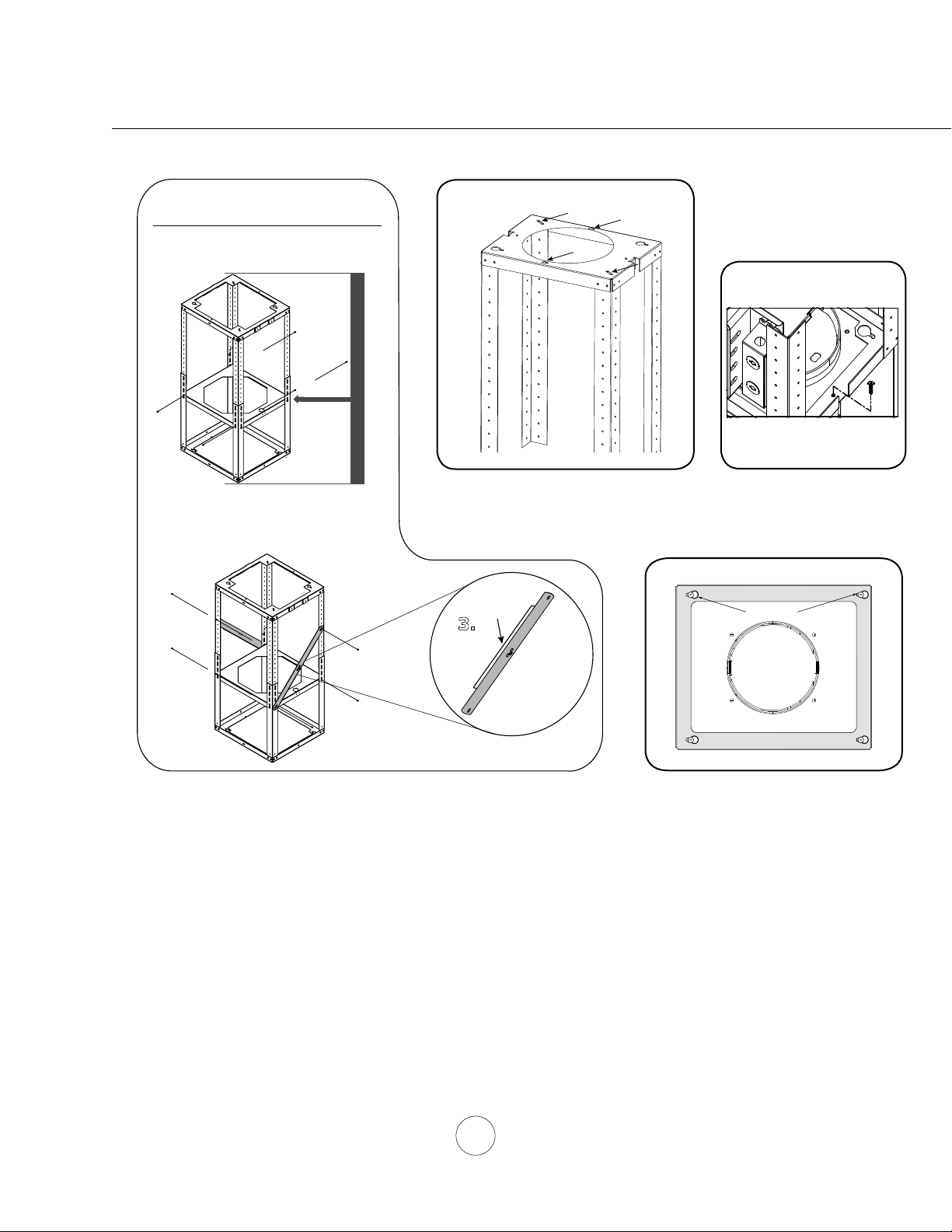
Duct Cover Standard Frame
Assembly Instructions
1.
2.
1/2
bottomtop
3.
FIG. F
Bottom Support Frame
(secures to top of blower housing)
Key Holes
front - facing controls
back
FIG. E
3. Attach square support bracket inside the support frame assembly. The placement of the square support bracket should
preferably be aligned in the middle where the top and bottom frame intersect (FIG. C1) Install (8) M4 x 8 screws to
secure the square support bracket onto the frame. Mount diagonal support brackets onto the support frame assembly
facing away from each other in a crossed formation (FIG. C2). The diagonal support brackets have a ledge on the side.
During installation, mount the diagonal support brackets with the ledge facing inwards to the unit (FIG C3). Install (4) M4
x 8 screws to secure the diagonal support brackets onto the frame.
4. Lift support frame assembly up to the ceiling making sure the word “front” on the top support frame faces the front of the
hood where the controls will be located (FIG. D). The key holes on the top support frame should cover the wood screws
previously installed in the ceiling. Slide support frame towards narrow end of key holes to lock the frame in place. Install
the last (4) M6 x 2” wood screws with washers into the four remaining holes of the top support frame to secure it to the
ceiling. (2) M6 x 2” wood screws with washers are installed on the corners and the other (2) M6 x 2” wood screws are
installed on the front and rear long sides of the support bracket (FIG. D). Tighten all screws.
5. Install the (4) 3/16 x 7/8 mounting screws on the top four corners of the unit body (FIG. A4). Lift hood and align the
mounting screws with the (4) key holes on the Bottom of Support Frame (FIG. E). Slide hood towards the narrow end of
key holes to lock into place. Hand tighten each of the (4) screws with a screwdriver to secure hood to Bottom Support
Frame. Further secure bottom support frame to unit body by one M4 x 12 safety screw (FIG. F).
Installation – Mounting the Hood
FIG. C
FIG. D
Top Support Frame
Side
Front
Loading ...
Loading ...
Loading ...