Loading ...
Loading ...
Loading ...
- 5 -Dimplex Industrial Fan Heater
Models : CFH60, CFH90 & CFH120
UK
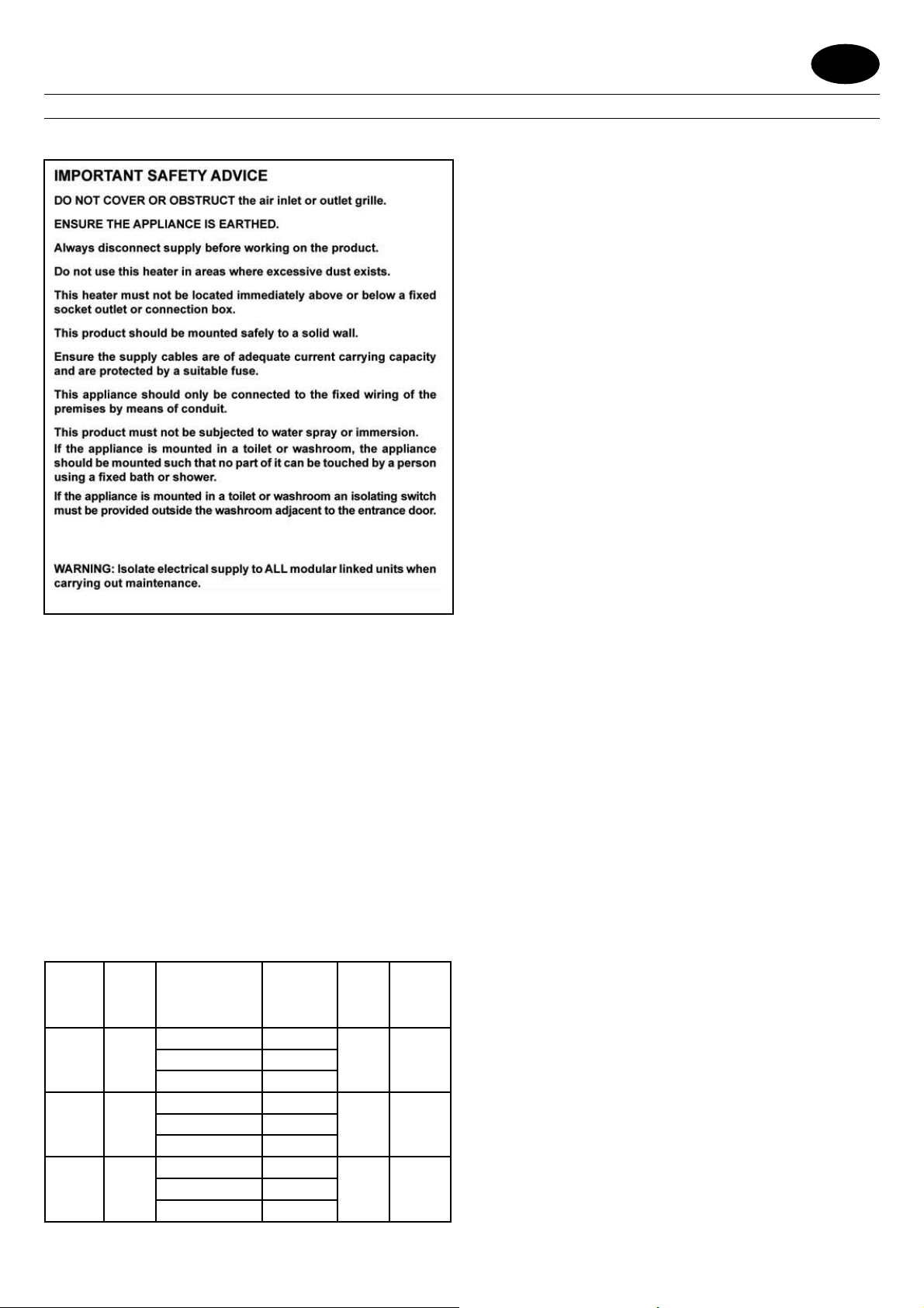
IMPORTANT: THESE INSTRUCTIONS SHOULD BE READ CAREFULLY AND RETAINED FOR FUTURE REFERENCE
General
A range of robust, high power wall mounting fan heaters designed to
coordinate with the Dimplex range of Air Curtains, providing environmental
heating in commercial and light industrial environments.
The heaters work by gradually raising the air temperature in the building
and should be positioned so as best to achieve an even temperature
distribution.
The product range has outputs of 6kW, 9kW and 12kW, and each product
contains on-board electronics that enables ‘daisy-chain’ linking to an
electronic control panel (CFCH) or building energy management system.
Connectivity between heater and control panel is achieved using LAN
(Local Area Network) cable i.e. CAT5, CAT5E or CAT6, pin confi guration is
straight through 1 to 1.
The electronic controller has a number of features including thermostatic
control. For more details on these refer to the CFCH instruction leafl et.
The switch panel CFCH should not be installed in a toilet or bathroom.
Model Heat
Output
kW
Electrical
Supply
Electrical
Load
(per phase)
A
Weight
KG
Min
Installed
height M
CFH60 3 / 6
220-240V~ 1PN 26.0
13 2220-240V~ 3P 15.6
380-415V~ 3PN 9.0
CFH90 6 / 9
220-240V~ 1PN 38.8
14 2220-240V~ 3P 23.0
380-415V~ 3PN 13.3
CFH120 6 / 12
220-240V~ 1PN 51.6
14 2
220-240V~ 3P 30.4
380-415V~ 3PN 17.5
Wall Mounting
Remove the wall mounting bracket from the back of the heater and using
it as a guide (see Fig. 2) mark off the hole positions on a suitable wall
(a minimum of 2 metres is required from the fl oor level to the bottom of
the bracket). Solid brick or concrete walls must be drilled and plugged.
Fix the wall mounting bracket to the wall and assemble the heater to the
extension tube using a bolt and wiring nut fi tted into hole 1 shown in Fig
3a. Rotate the heater as shown in Fig. 3b, and fi x the heater into position
using the remaining bolt and wing nut in hole 2. Pivot and rotate the
heater into the desired position and tighten all three wing nuts. A 6mm
Allen key can be used as an aid to tightening the bolts.
Electrical and Control Connections
Note: The installation of this appliance should be carried out by a
competent electrician and be in accordance with the current IEE
wiring regulations.
All products are fi tted with microprocessor control. Electrical power and
control connections for all CFH models are made by removing the control
housing and bottom panel. The control housing (‘y’ in Fig. 4) is detached
by removing the two quick release fasteners and hinging the housing
as shown. The bottom panel (‘x’ in Fig. 4) is detached by removing two
screws and lifting off as shown.
Note: A suitable local isolating switch must be provided in the electrical
supply circuit as close as possible to the heater with at least 3mm
clearance on each pole.
Wiring Diagrams Fig. 7
A - PCB
B - Mains in terminal blocks
C - Cut-out circuit
D - LAN Sockets
E - Elements
M - Motor
Feed appropriate supply cable (see ‘x’ in Fig. 5) to terminal blocks ‘z’.
Make electrical connections as shown in Fig. 7 and fi x the cable in back
panel using cable gland. Using LAN cable (see ‘y’ in Fig. 5) make the
control connections to BUS IN socket ‘w’ also shown in Fig. 5. Fix this
cable in the back panel using cable gland and feed back to the electronic
control panel (CFCH) using suitable conduit if required. Refer to CFCH
instructions for installation and connections of electronic control panel.
Replace the bottom panel and control housing and switch on power
to heater and installed electronic control panel. Ensure that all control
settings function correctly.
Note: The factory supplied unit can accept three phase voltage of ~380-
415V. For single phase 220-240V and three phase ~220-240V refer
to the electrical wiring label fi xed to the underside of the bottom panel.
To change between different voltage systems, rearrange the push-on
connections as per the required wiring diagram. Contact your supplier for
further details.
Operation using Control Panel - CFCH
Switch on electrical supply to the fan heater and the electronic control
panel. When all units are powered up and there is a connection between
the controller and the master unit, an LED will turn on in the controller to
indicate the units are functioning. Refer to the CFCH instruction leafl et on
the operation of the electronic control panel.
Do not switch the heater off at the isolator when the unit is running as
this will prevent the fan overrun operating. This can cause a nuisance
cut out as the excess heat cannot be dissipated.
Loading ...
Loading ...
Loading ...