Required tools
Ruler4 AA Batteries
Hammer Wood block
Phillips head screwdriver
Additional Tools (depending on application)
A
K or L
(2x)
KL
N
M
A
A
B
B
B
A
B
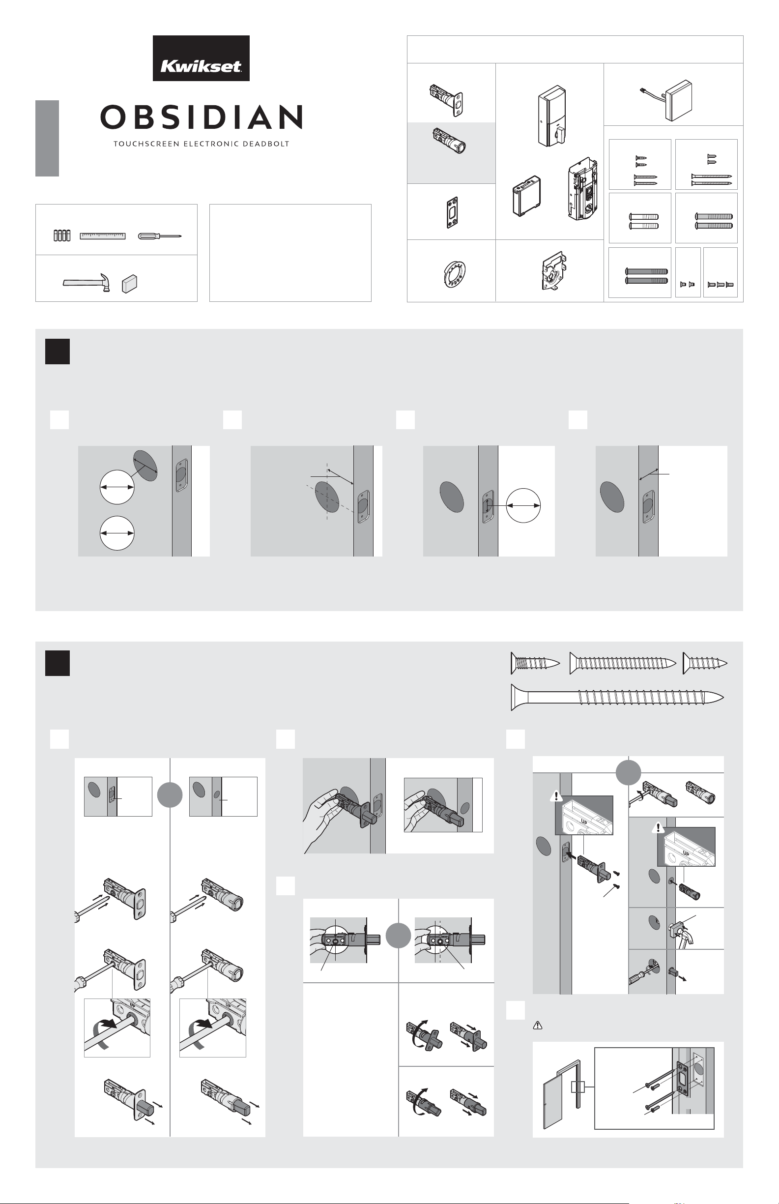
If drilling a new door, use the supplied template and the complete
door drilling instructions available at www.kwikset.com/doorprep.
Note: Additional door preparation may be
required for doors with 11/2" (38 mm) holes.
Consult the deadbolt drilling instructions at
www.kwikset.com/doorprep.
or
backset
Measure to conirm that the hole in
the door is either 21/8" (54 mm) or
11/2" (38 mm).
Measure to conirm that the backset is
either 23/8" or 23/4" (60 or 70 mm).
23/8" or 23/4"
60 or 70 mm
13/8" –2"
35 – 51 mm
Measure to conirm that the hole in
the door edge is 1" (25 mm).
Measure to conirm that the door is
between 13/8" and 2" (35 mm and
51 mm) thick.
A
A B
C
D
B C D
Is the door edge chiseled?
Is the D-shaped hole centered in the door hole?
Which latch are you installing?Hold the latch in front of the door hole, with the latch
face lush against the door edge.
21/8"
54 mm
11/2"
38 mm
1"
25 mm
YES
YES
NO
NO
Use latch “A”. If the
latch bolt is not already
extended, extend the
latch bolt as shown.
No adjustment is required.
Proceed to next step.
D-shaped hole D-shaped hole
Rotate latch face as
shown to extend latch.
wood
block
actual
size
Use latch “B” (not
included). If the latch
bolt is not already
extended, extend the
latch bolt as shown.
Latch “A” Latch “B”
N (2x)
C
M (2x)
Longer screws
install closest to
the door jamb.
door frame
E
Install strike on the door frame.
Make sure the hole in the door frame is drilled a
minimum of 1" (25 mm) deep.
or
chiseled
not
chiseled
or
1
Prepare the door and check dimensions
2
Install the latch and strike
or
Latch
“B” is not included. If needed,
please contact Kwikset to order
a drive-in latch for your lock.
Strike
C
A
B
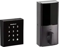
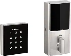
Exterior Touchscreen
Adapter
Ring
D
Mounting
Plate
Parts in the box
Fasteners
03809 46780
K
M
N
L
64109
U
49191
T
Interior Assembly
G
F
H J
E
64843
64845
Q
S
64844
R
(1-3/8" • 35 mm)
(2" • 51 mm)
(1-3/4" • 44 mm)
1 / 4
ENGLISH
66466001
Rev 02
953
Installation and User Guide
Kwikset
Technical Support
1-800-327-5625
www.kwikset.com
21/8"
54 mm
11/2"
38 mm
What is the thickness of your door?
Use the shorter
gold screws.
Use the medium
silver screws.
1-3/8" (35 mm) 1-3/4" (44 mm) 2" (51 mm)
Use the longer
black screws.
or or
1-3/8"
35 mm
1-3/4"
44 mm
2"
51 mm
QR S
actual
size
Q (1-3/8" / 35 mm)R (1-3/4" / 44 mm)
S (2" / 51 mm)
2 / 4
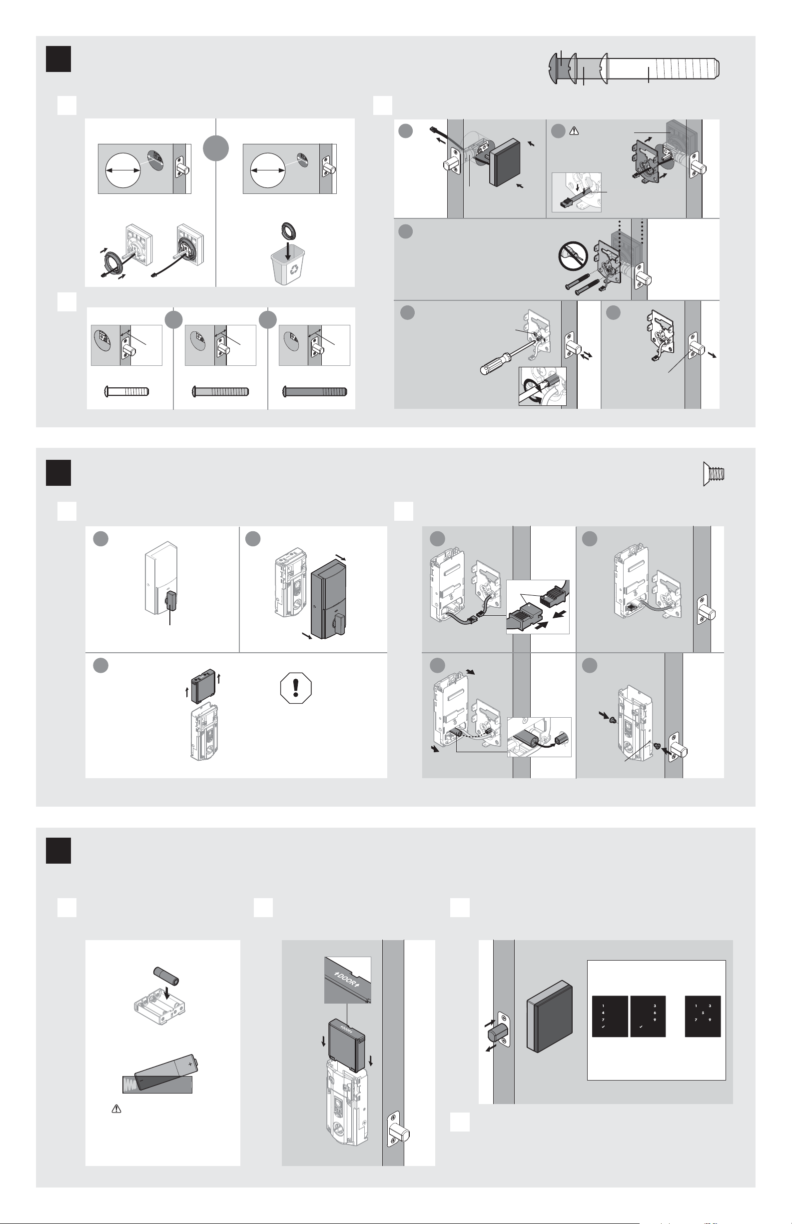
What is the diameter of the hole in the door? Install exterior touchscreen and mounting plate.
A
B
C
Diameter is 2-1/8"
(54 mm)
Diameter is 1-1/2"
(38 mm)
or
“D” is required for installation.
Install “D” on “F”.
“D” is not needed for
installation. Discard “D”.
Cable goes
underneath latch.
Support exterior
assembly during
mounting plate
installation.
Insert the tip of a Phillips
screwdriver into the
torque blade.
screws
Keep parallel to
edge of door.
Tighten screws evenly.
a
c
b
d
Remove battery cover and battery pack from interior assembly. Install interior assembly onto mounting plate.
A B
a
c
b
Make sure turnpiece is in
the vertical position.
H
H
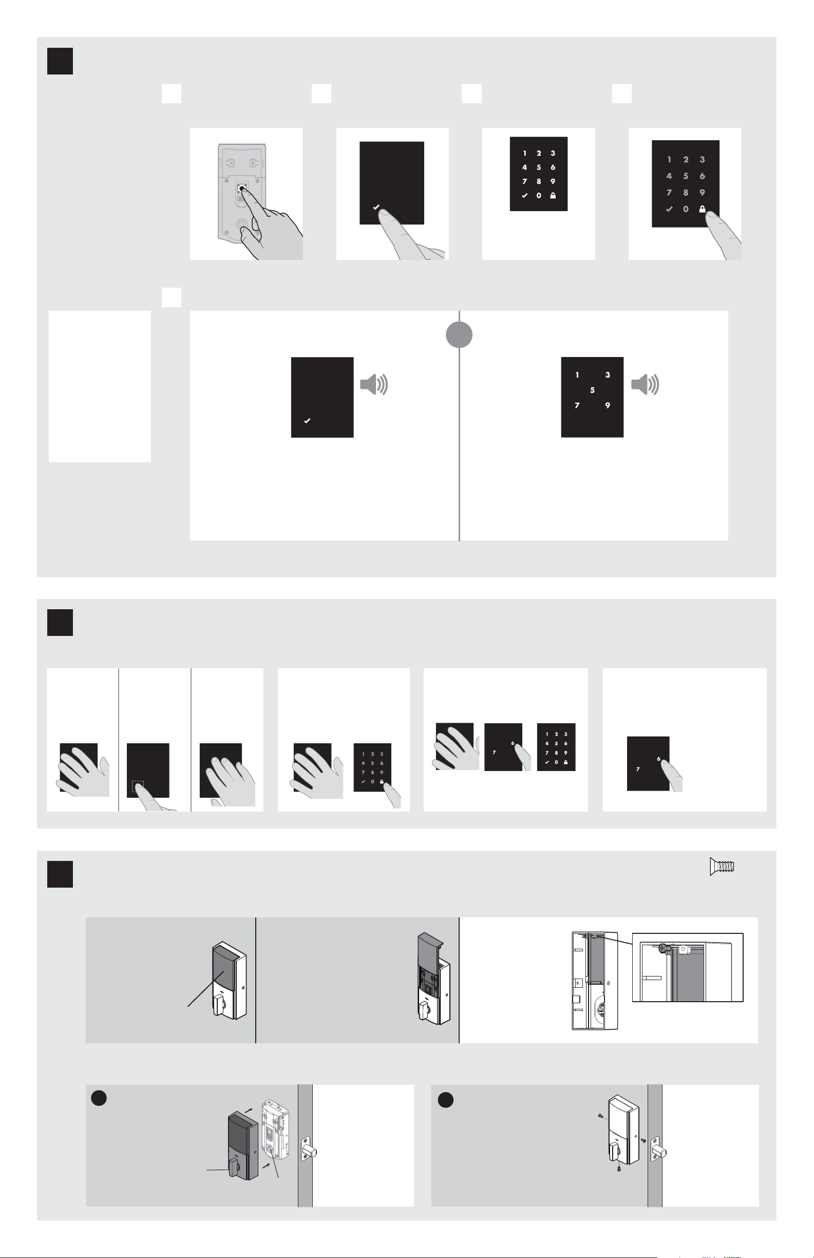
This step will teach your lock the orientation of your door and is crucial to lock operation.
Install 4 AA batteries in battery pack. Make sure the door is open, and
insert the battery pack.
After a few seconds, the latch bolt will retract and extend on
its own to learn the orientation of the door. This is called the
door handing process, and it is crucial to lock operation.
If the touchscreen indicates a failure make sure that
the cables are connected, the batteries are installed
correctly, and attempt this procedure again.
If the door handing process is still unsuccessful after a second
attempt, perform the “Manual Door Handing” procedure on page 4.
A B C
D
Ensure correct polarity.
For best results, use
new, non-rechargeable
Alkaline batteries only.
Ensure tight cable
connection.
Lay excess cable lat inside the
bottom of the interior housing.
align
J
a
c
b
d
T
(2x)
T
actual
size
bottom
hole
J
G
J
H
4
Install the interior assembly
5
Install the batteries and perform the door handing process
Do not install
batteries until step 5.
Once the door handing process
is complete, the touchscreen
will indicate success or failure:
Success:
lashing checkmark
symbol and single
column of digits
Failure:
lashing
“X” pattern
extended
Make sure
the latch
bolt is fully
extended.
Apply slight pressure
while rotating the torque
blade to test for smooth
latch operation.
Route cable through
center hole, then push
cable into bottom hole.
If the latch does not retract
and extend smoothly, adjust
the mounting screws.
D
D
F
F
Q, R, or S (2x)
E
e
3
Install the exterior touchscreen
1x 3x
U (3x)
G
Note: The interior
cover and screws
must be removed for
battery pack access.
3 / 4
Conirm that the code(s) added in previous step can unlock the door.
Checkmark symbol with one beep
Option 1
Touch screen with
palm or back of
hand until digits
illuminate.
Option 2
Touch lower left
area of screen
(where checkmark
is located) until
digits illuminate.
Option 3
Touch screen
with three or
more ingers until
digits illuminate.
“X” pattern with three beeps
or
Make sure the door is
open. Press the Program
button once.
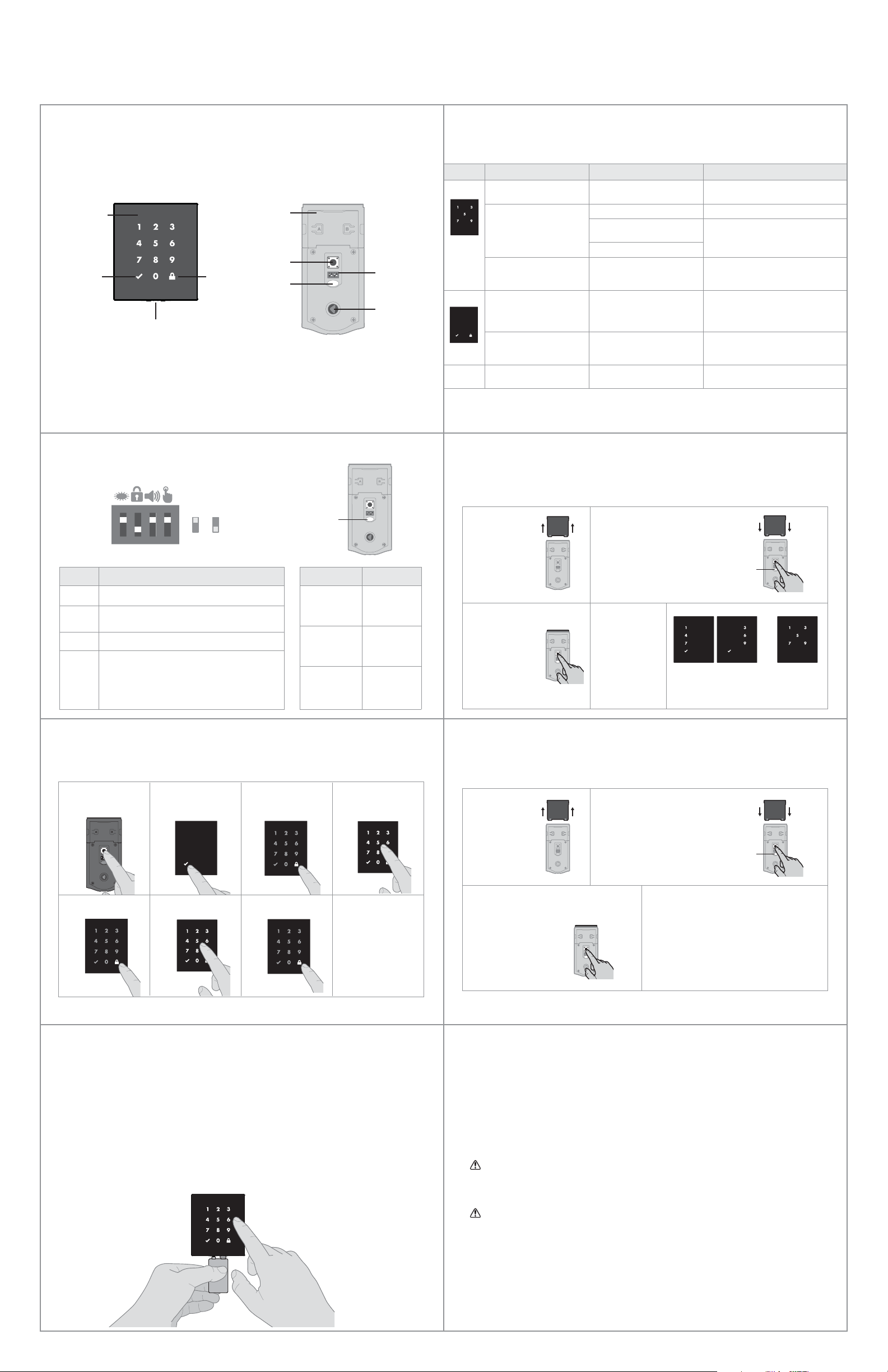
Activating the Screen Locking the Door Unlocking the Door SecureScreen™
Press checkmark
symbol once.
Enter user code. A total
of 16 user codes may
be programmed.
Press lock symbol once.
A B C D
What digits and sounds did the lock produce?
E
Programming Timeout
During programming, if the
screen is not pressed for 20
seconds, the system will time
out (indicated by three beeps
and the “X” pattern lashing
three times), and you will need to
restart the procedure.
Programming was successful. Programming was unsuccessful.
Make sure the user code is not a duplicate and that it is between
4 and 8 digits during your next attempt.
Make sure the lock has room for an additional code. If all user code
positions are illed, delete a code to make room for this one.
1. Activate the screen.
2. Press Lock symbol.
Note: If no user codes are
programmed, the door cannot
be locked via touchscreen.
1. Activate the screen.
2. If SecureScreen is enabled, touch
the random digits that appear.
3. Enter user code.
If you press the wrong digit while entering
a user code, you can press the Lock symbol
once to clear the digits entered previously and
immediately restart the code entry process.
If desired, this feature
can be disabled by
turning switch #4 to
the o position. See
“Switches and Status
LED Colors” on page 4.
SecureScreen is an added-security feature
that displays random digits before you enter
a user code to unlock the door. This feature
ensures that there are ingerprints on all
digits so that codes cannot be identiied by
examining the touchscreen for inger prints.
Each user code must be
a unique code between
4 and 8 digits.
*Beeping sound will only be heard if switch #3 (on the lock interior) is in the on positon. See “Switches and Status LED Colors” on page 4.
Mastercode
For enhanced security,
a mastercode may
be used when adding
and deleting user
codes. For more
information about the
mastercode, download
the Programming and
Troubleshooting Guide
on the Obsidian page
at www.kwikset.com.
U
6
7
window
If you wish to unlock
the window, you can
slide it up for more
convenient access
to the programming
buttons while the
cover is installed.
To unlock the
window, remove
the security screw.
The window
on the interior
cover is locked
by default to
prevent someone
from tampering
with your lock's
settings.
Important Information about the interior cover
Cover Installation
Install cover.
Note: You may need to
rotate the turnpiece to align
with the turnpiece shaft.
turnpiece
turnpiece
shaft
Install screws.
a
b
Install the interior cover
8
actual
size
Add user codes (16 max)
Test the lock (review normal operation)
Display Alert Reason Solution
“X” pattern lashes one time
with one beep*.
One incorrect code entered. Re-enter code.
“X” pattern lashes three
times with three beeps*.
No user code programmed. Program at least one user code.
Programming timeout after 20
seconds.
Attempt programming procedure again.
Unsuccessful programming.
“X” pattern lashes 15 times
with 15 beeps*
Three incorrect codes entered
within one minute.
Re-enter code after 60 second
touchscreen lockout.
Checkmark and lock symbols
lash simultaneously ive
times with long continuous
beep*.
Low battery. Replace batteries.
Checkmark and lock symbols
alternate lashing ive times
with long continuous beep*.
Door jammed while attempting
to lock.
Manually re-lock door. If needed,
reposition strike.
N/A Lock beeps continuously.
Interior assembly is
disconnected from exterior.
Remove battery pack, reconnect the interior
to the exterior, then replace battery pack.
Status
LED
If the touchscreen indicates a failure, see the
online Programming and Troubleshooting Guide
or call Technical Support.
Note: All codes may be deleted at once if the mastercode is enabled. For more information about the
mastercode, consult the online Programming and Troubleshooting Guide.
© 2017 Spectrum Brands, Inc.
Exterior
Touchscreen
Checkmark
symbol
Lock
symbol
Emergency
Power 9 Volt Port
Success Failure
4 / 4
Obsidian at a Glance System Alerts
Switches and Status LED Colors
Deleting a single user code Factory Reset
*Beeping sound will only be heard if switch #3 is on.
If the screen is not pressed for 20 seconds, the system will time out,
and you will need to restart the procedure.
A factory reset will delete all codes associated with the lock, and it will
remove it from your smart home system.
1. Read all instructions in their entirety.
2. Familiarize yourself with all warning and caution statements.
3. Remind all family members of safety precautions.
4. Protect your user codes and mastercode.
5. Dispose of used batteries according to local laws and regulations.
CAUTION: Prevent unauthorized entry. Since anyone with access to the back panel can
change the user codes, you must restrict access to the back panel and routinely check the
user codes to ensure they have not been altered without your knowledge. The use of a
mastercode can help protect your system’s settings.
WARNING: This Manufacturer advises that no lock can provide complete security by itself.
This lock may be defeated by forcible or technical means, or evaded by entry elsewhere
on the property. No lock can substitute for caution, awareness of your environment, and
common sense. Builder’s hardware is available in multiple performance grades to suit the
application. In order to enhance security and reduce risk, you should consult a qualiied
locksmith or other security professional.
Switch Function
1 Door lock status LED blinks every 6 seconds
2
Lock automatically re-locks door 30 seconds after
unlocking. Disabled if no codes are programmed.
3 Audio
4
SecureScreen feature displays random digits to be
pressed before entering user code. This added-
security feature ensures that there are ingerprints
on all digits so that codes cannot be identiied by
examining the touchscreen for ingerprints.
Color Lock Status
Blinking green Unlocked
Blinking amber Locked
Blinking red Low battery
Reference Guide
Important Safeguards
Back
panel
Program
button
Status
LED
Switches
Turnpiece
shaft
Note: When the cover is removed,
the turnpiece shaft can be used to
manually lock and unlock the door.
If needed, the door handing process can be initiated manually.
This is useful if the lock is being moved to a di erent door.
Interior (cover removed)
1 2 3 4
On
Switches
Status
LED
O
Manual Door Handing
3 Press the Program
button once more.
4 The latch bolt
will extend and
retract to learn
the orientation
of the door.
1 Remove
battery pack.
2 Press and HOLD the Program
button while reinserting the
battery pack.
Release button once battery
pack is installed. The status LED
will lash red and green.
Status
LED
1 Remove
battery pack.
3 Press the Program button
once more. The status
LED will lash green and
red several times.
2 Press and HOLD the Program
button while reinserting
the battery pack.
Keep holding the button for 30
seconds until the lock beeps
and the status LED lashes red.
4 After a few seconds, the lock will
initiate the door handing process, and
the latch bolt will extend and retract
to learn the orientation of the door.
1 Keep door open.
Press Program
button once.
2 Press Checkmark
symbol once.
3 Press Lock symbol
once.
4 Enter user code to
be deleted.
5 Press Lock symbol
once.
6 Re-enter user code. 7 Press Lock symbol
once.
If unsuccessful
Make sure to enter
the same valid code in
steps 4 and 6.
Test code
While the door is open,
test the user code to
make sure it no longer
unlocks the door.
Low Battery
If the 4 AA batteries are too low to operate the lock, use a 9Volt Alkaline battery to temporarily
power the touchscreen.
Make sure both terminals on the 9Volt battery touch the terminals at the bottom of the
touchscreen. Hold the 9Volt in place while entering your user code to unlock the door. Continue
holding the 9Volt in position until the Checkmark symbol illuminates and the door unlocks.
Note: If you remove the battery before the Checkmark symbol illuminates, you will need to re-enter
your user code