The remote can be mounted in a variety of ways. Use the following instructions to mount the remote that suits your application.
1. Find a location that gives easy access to the remote.
2. Route the cable for the remote and connect to the amplifier, figure 1.
Outside Panel Install
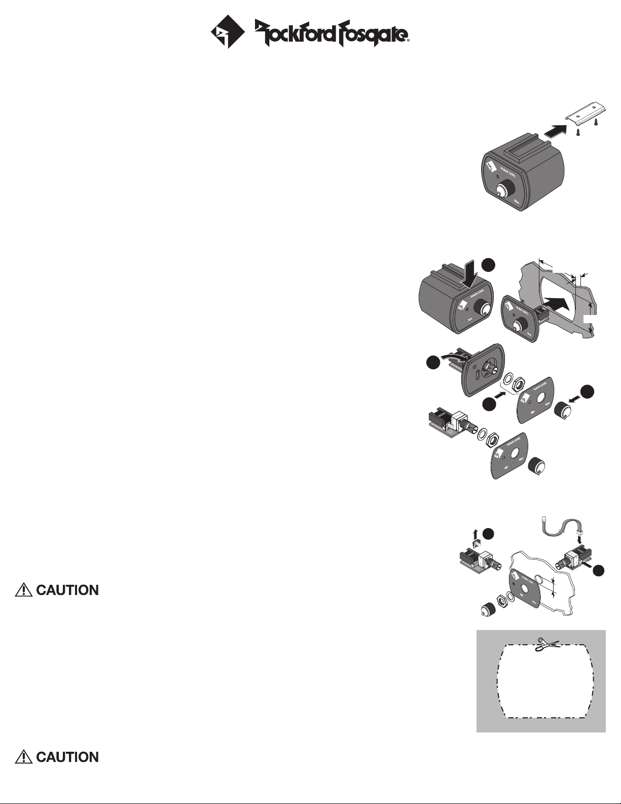
3. Using the screws supplied, install the mounting clip.
NOTE: The housing can be installed with the mounting tab up or down. See step 1 in figure 2,use a
small flat-blade screwdriver in the slot at the top of the remote and pry the remote assembly from
the housing. Reinstall housing as desired.
4. Slip the remote onto the mounting clip until it snaps into place.
5. Connect the cable to the back of the remote.
Panel Install-With Front Housing
The maximum panel thickness is 1/8” (0.125” or 3.18mm) for this type of installation.
Disassemble the remote as shown in figure 2 as follows;
Ensure there is enough room within the panel area for connection and placement.
1. Use a small flat-blade screwdriver in the slot at the top of the remote and pry the remote assembly from the
housing.
2. Cut a hole into the panel using the Hole Cut Template at the bottom of the page.
3. Run the cable to the hole,connect to the remote assembly and snap into place.
Panel Install-Without Housing-Disassembly
NOTE: The maximum panel thickness is 3/16” (0.1875” or 4.75mm) for this type of installation.
Disassemble the remote as shown in figure 2 as follows;
1. Use a small flat-blade screwdriver in the slot at the top of the remote and pry the remote assembly from the
housing.
2. Pull the control knob straight off to remove.
3. Use a paper clip or the flat side of a small drill bit from the back side through the hole to push the cover plate
off the housing cover.
NOTE: If the clear plastic LED extender is attached to the cover plate, remove it.
4. Remove the nut and washer and remove the remote assembly from the housing cover.
Panel Install-Standard
Ensure there is enough room within the panel area for connection and placement.
1. Use either plate with the LED hole as a template for hole positions.
2. Drill a 9/32” hole (0.281” or 7.14mm) for the knob shaft and a 3/32” hole (0.094” or 2.39mm) for the LED through hole.
3. Install the remote from the back side of the panel,aligning the knob shaft and LED with the drilled holes.
4. Install the cover plate washer and nut. Do not over-tighten the nut,just tighten until firm and secure.
5. Turn the knob shaft counter-clockwise to it’s lowest setting. Position and install the knob.
6. Connect the cable to the back of the remote.
Panel Install-Separated LED Placement
We suggest the following be done only by an experienced installer. Use of a grommet and/or double-sided
tape (both not included) may be needed for a proper fit of the LED. Rockford Fosgate will in no way be held
responsible for damage incurred by improper or novice installation.
Ensure there is enough room within the panel area for connection and placement.
1. Remove the LED from the remote assembly by pulling straight up, figure 3.
2. Connect the cord with the LED attached into the 2-pin connector behind the knob shaft housing.
3. Drill a 9/32” hole (0.281” or 7.14mm) for the knob shaft.
4. Install the remote from the back side of the panel, aligning the knob shaft with the drilled hole.
5. Install the smaller cover plate, washer and nut. Do not over-tighten the nut, just tighten until firm and secure.
6. Turn the knob shaft counter-clockwise to it’s lowest setting. Position and install the knob.
7. Locate the position of the LED hole where the cord is not being over-extended.
8. Depending on the method of mounting,either a grommet and/or double-sided tape, drill the hole for a snug fit. Install the LED.
9. Connect the cable to the back of the remote.
Operation
Over excursion and subsequent damage may occur at high levels of boost
Use the Installation and Operation manual that came with your amplifier for proper operation of the remote.
Hole Cut
Template
1
2
3
4
1-5/16˝
1/8˝
1˝
2
1
9/32˝
PUNCH Level Control Remote Mounting Install
Figure 1
Figure 2
Figure 3
Printed in China11/12 1230-58154-01