Loading ...
Loading ...
Loading ...
Level
the appliance using the feet as
illu
strated in figure 8:
a.
t
urn the nut clockwise to release the
scr
ew;
b. rotate the foot to raise or lower it until it
touches to the floor;
c.
lo
ck the foot, screwing in the nut, until it
t
ightens against
t
o the bottom of the
w
ashing machine.
P
lug in the appliance.
A
B
C
8
The det
ergent draw is split into 3
c
ompartments as illustrated in figure 9:
com
partment "1": for prewash detergent;
com
partment “
”:
for special additives,
s
ofteners, starch fragrances, etc.;
com
partment "2": for washing detergent.
A
liquid detergent cup is also included
IN
SO
ME MODELS (fig. 10)
.
To use it, place it
in
compartment "2"
.
This way, liquid
detergent will only enter the drum at the
ri
ght time. T
he c
up can also be used for
bleach when the “Rinse” program is
s
elected.
2
1
9
10
W
ARNING:
contact the Customer Service Centre
should the power cord need
replacement.
D
etergent drawer
W
ARNING:
only use liquid products; the washing
machine is set to automatically dose
additives at each cycle during the last
rinse.
W
ARNING:
some detergents are hard to remove.
In this case we recommend using the
specific container to be placed in the
drum (example in figure 11).
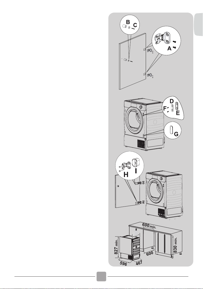
Fix
the hinges in place (on the
door)
with
the 4 screws
provided (A) (figure 4).
Fix
the magn
et (B) in place
using screw (C) (figure 4).
Mount the plate (D) on the right
or left-
hand side, depending on
your installation
requirements
(figure 5).
Place the plastic support (E)
under
the plate and fix it in
posit
ion with screw (F) (figure 5)
.
Snap moun
t cap (G) in the
lower position (figure 5).
Mount the furniture door to the
front of the dryer using the
hinges.
Place the spacers
under the hinges
(I) (figure 6)
and then fix in
posit
ion with
screw (H).
Slide the dryer into an opening
of the size indicated in the
diagram (figure 7).
Figure 4:
Figure 5:
Figure 6:
Figure 7
:
Fix the hinges in place (on the
door)
with the 4 screws
provided (A) (figure 4).
Fix
the magn
et (B) in place
using screw (C) (figure 4).
Mount the plate (D) on the right
or left-
hand side, depending on
your installation requirements
(figure 5).
Place the plastic support (E)
under the plate and fix it in
posit
ion with screw (F) (figure 5)
.
Snap moun
t cap (G) in the
lower position (figure 5).
Mount the furniture door to the
front of the dryer using the
hinges. Place the spacers
under the hinges
(I) (figure 6)
and then fix in
posit
ion with
screw (H).
Slide the dryer into an opening
of the size indicated in the
diagram (figure 7).
Figure 4:
Figure 5:
Figure 6:
Figure 7
:
'R
QRWLQVWDOOWKHSURGXFWLQD
ORZ WHPSHUDWXUH URRP RU LQ D
URRPZKHUHWKHUHLVDULVNRIIURVW
RFFXUULQJ$WWHPSHUDWXUHDURXQG
IUHH]LQJ SRLQW WKH SURGXFW PD\
QRW EH DEOH WR RSHUDWH SURSHUO\
WKHUH LV D ULVN RI GDPDJH LI WKH
ZDWHULVDOORZHGWRIUHH]HLQWKH
K\GUDXOLF FLUFXLW YDOYHV KRVHV
SXPSV )RU D EHWWHU SURGXFW
SHUIRUPDQFH WKH DPELHQW URRP
WHPSHUDWXUH PXVW EH EHWZHHQ
& 3OHDVH QRWH WKDW
RSHUDWLQJ LQ FROG FRQGLWLRQ
EHWZHHQ DQG & PLJKW
VLPSO\VRPHZDWHUFRQGHQVDWLRQ
DQGZDWHUGURSVRQIORRU
3UHYHQW
LWHPV IURP IDOOLQJ RU
FROOHFWLQJ EHKLQG WKH GU\HU DV
WKHVHPD\REVWUXFWWKHDLULQOHW
DQG RXWOHW 1(9(5 LQVWDOO WKH
GU\HUXSDJDLQVWFXUWDLQV
Ɣ
$LU2XWOHWVLQWKH%DVH
:
$51,1* 7KH DSSOLDQFH
PXVWQRWEHVXSSOLHGWKURXJK
DQ H[WHUQDO VZLWFLQJ GHYLFH
VXFKDVDWLPHURUFRQQHFWHG
WR D FLUFXLW WKDW LV UHJXODU\
VZLWFKHGRQDQGRIIE\DXWLOLW\
,I
WKHVXSSO\FRUGLVGDPDJHG
LW PXVW EH UHSODFHG E\ WKH
PDQXIDFWXUHULWVVHUYLFHDJHQWRU
VLPLODUO\ TXDOLILHG SHUVRQV LQ
RUGHUWRDYRLGDKD]DUG
7KH
SOXJVKRXOGEHDFFHVVLEOHIRU
GLVFRQQHFWLRQ DIWHU WKH DSSOLDQFH
KDVEHHQLQVWDOOHG
Ɣ
487
EN
9
Loading ...
Loading ...
Loading ...