Loading ...
Loading ...
Loading ...
4 • English PowerSpace P4300+/P4150+ • Installation Guide
PRO.BOSE.COM
Product Details
PowerSpace P4300+/P4150+
Front Panel
PowerSpace Versatile Power Amplifier
1
POWER
SIGNAL
LIMIT
2
3 4
P4300+
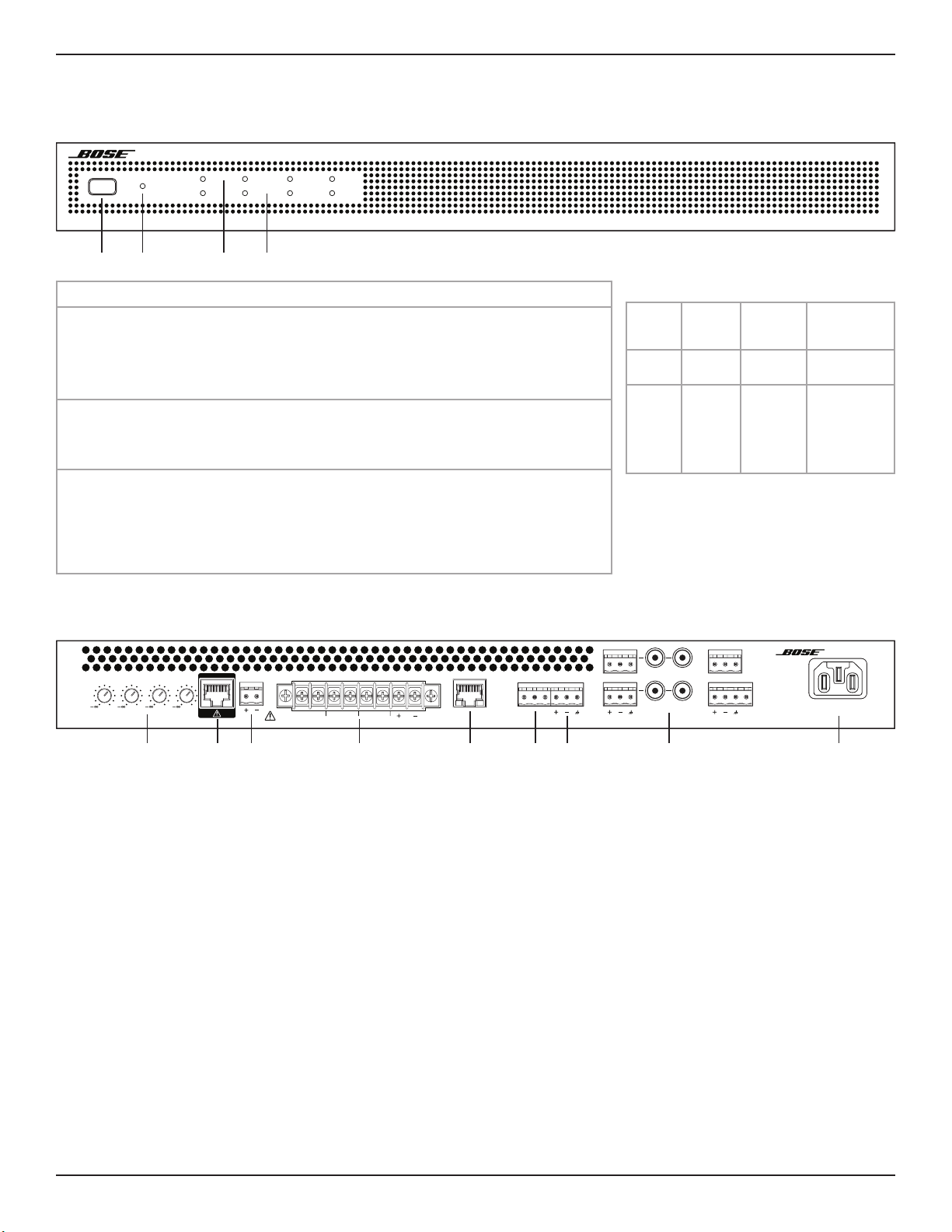
q Power switch:
In/Out standby mode.
w Power LED:
Power or fault state
indication.
White (solid): Power is on
White (blinking): Unit is in standby mode
Red (solid): Power supply fault
Red (blinking): Thermal fault
e Input Signal LED:
Each LED operates
independently.
Green: Signal present
Amber: Input is near clipping
Red: Input is clipping
r Output Limit LED:
Each LED operates
independently.
Amber: Amplifier limiting an output
Red (solid): Ch 1 & Ch 2 amplifier A fault
Ch 3 & Ch 4 amplifier B fault
Red (all solid): Thermal fault
Red (blinking): Outputs are muted
q w e r
Rear Panel
100-240V ~ 50/60HZ
570W MAX
PowerSpace P4300+
Versatile Power Amplifier
2
0
1
0
4
0
3
0
OUTPUT ATTENUAT ION MUTE OUTPUT
CLASS 2
WIRING
3412
ControlCenter ONLYControlCenter ONLY
ETHERNET
AUX OUT
LINE LEVEL
MOH OUT
600 Ω
4
3
2
1
PTT
INPUT
q Output Attenuation controls: Output attenuation controls for each output. Turn the controls clockwise to decrease attenuation and
counter-clockwise to increase attenuation. The attenuator must be at 0 dB attenuation for the respective output to reach rated power.
w ControlCenter port: RJ-45 input connector for CC-1, CC-2, CC-3 ControlCenter analog zone controllers or CV41 4-to-1 converter only.
e Mute port: Normally open or normally closed dry contacts can mute all outputs. Mute polarity can be inverted in the configuration utility.
r Output terminal block: 8-terminal block connector for loudspeaker connections. Each channel can deliver up to 300 watts (P4300+)
and up to 150 watts (P4150+) regardless of load into 4, 8, 70V, or 100V. Each output pair can be I-Shared with an added jumper.
Wire the I-Share 1 & 2 loudspeaker load to the amplifier using terminals 1+ and 1– (or 2+ and 2–). Wire the I-Share 3 & 4 loudspeaker
load to the amplifier using terminals 3+ and 3– (or 4+ and 4–).
t Ethernet port: Connect amplifier to a network switch or laptop Ethernet port to configure via the PowerSpace configuration utility.
y Music-on-hold: Dedicated 600-ohm music-on-hold output.
u Auxiliary Output: Line-level auxiliary output.
i Input: Inputs 1 & 2 support balanced line-level inputs (Euroblock) or unbalanced inputs (RCA) The RCA inputs are each summed to
mono. Inputs 3 & 4 are balanced inputs, and Input 4 also supports either a 600-ohm telephone paging input or a PTT/VOX dynamic
microphone input.
o Power input: Power cord connection (IEC 60320-C14 inlet). Removing the power cord when the amplifier is on is equivalent to
powering down using the front panel power switch, and is an acceptable power-down method.
q ew r t y u i o
Setting Up a PowerSpace Plus Amplifier
1. Starting with the amplifier power O, make all required network, then audio, then network connections.
2. All configuration is done within the PowerSpace configuration utility:
Note: The PowerSpace configuration utility is compatible only with Google Chrome, Mozilla Firefox, Microsoft Edge, and Internet Explorer.
A. Visit bosepro.link/psasw and download the Discovery Tool application.
B. Connect your computer directly to the Ethernet port of your amplifier or via a network switch.
C. Open and run the Discovery Tool application.
D. Press the Power switch on the front panel to power the amplifier On.
E. In the application, click Refresh. The IP address of each amplifier in the network will appear in the window.
Faults Only
Power
Supply
Fault*
Thermal
Fault
Amplifier
Fault
Power
LED
Solid
red
Blinking
red
—
Limit
LEDs
— All solid
red
Ch 1 & 2
solid red,
Amplifier A
Ch 3 & 4
solid red,
Amplifier B
*Except for AC loss
If a power supply or amplifier fault cannot
be cleared, then the amplifier needs to be
replaced.
Loading ...
Loading ...
Loading ...