Loading ...
Loading ...
Loading ...
R600 and HSRL Series LP-Gas Regulators
6
Meter Installations
Type R642 regulators have an angle body that makes it
easy to install on to a gas meter instead of piping leading
directly into a building.
Meter and Type R642 with Vent over
Regulator Inlet:
Install the regulator per instructions given in the previous
section “Installation Location”.
Meter and Type R642 with Vent over the Regulator
Outlet and Installed over the Top of the Meter:
This installation orientation will put the Type R642
regulator vent in a vertical down position, but very close
to the top of the gas meter. The regulator vent may
become blocked during a freezing rain storm or heavy
snows. Therefore, some type of protective cover should
be installed over the regulator and meter or vent piping
should be installed so that the vent remains open.
Meter and Type R642 Regulator Installed Indoors:
Pipe the regulator vent per the section “Indoor Installations”.
Indoor Installations
By code, regulators installed indoors have limited inlet
pressure, and they require a vent line to the outside of the
building, see Figure 4. A vent assembly, such as
Fisher
®
Y602 Series, should be used on the end of the
vent line. The same installation precautions, previously
discussed throughout this manual for the regulator vent,
apply to the end of the vent tube assembly. Vent lines
must not restrict the gas ow from the regulator’s internal
relief valve. Vent lines should be at least 3/4-inch NPT
pipe or 3/4-inch NPT size, Gray PVC Schedule 40 Rigid
Non-metallic Electrical Conduit for above Ground Service,
per UL
®
651. To install the vent line, remove the vent
screen and apply a good grade of pipe dope to the male
threads of the line. Vent lines should be as straight as
possible with a minimum number of bends.
Underground Installations
CAUTION
Types R632A and R632E integral
regulators require 2 vent tubes, one on
the rst stage vent and one on the second
stage vent, when installed on underground
tanks. Failure to use 2 separate vent tubes
can result in early regulator failure and/
or over pressuring the second stage that
could result in res or personal injury.
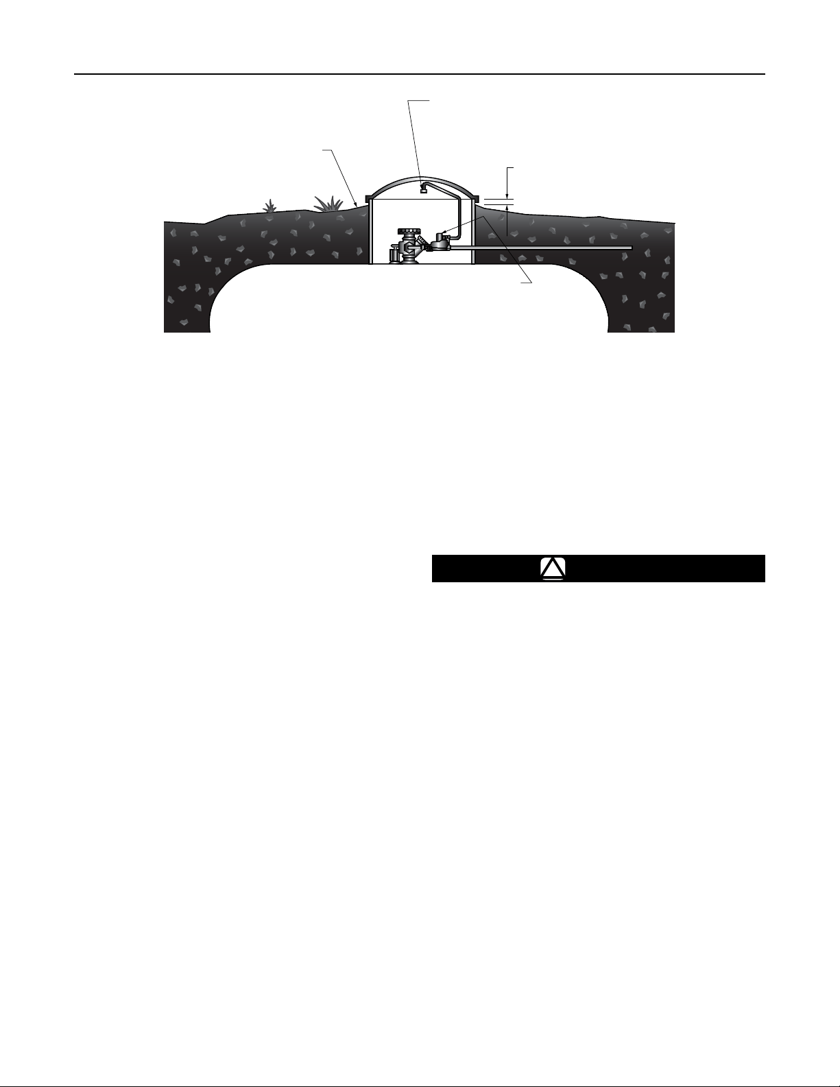
Regulators installed in the dome of an underground
container require a vent tube to prevent water from
entering the regulator spring case, see Figure 5.
Note
Types R632A and R632E integral regulators
installed on underground tanks require the
use of 2 vent tubes, one for the rst stage
vent (1/4-inch OD copper tube inverted are
connection: 7/16-24 UN thread) and the
other for the second stage vent (3/4 NPT) of
the regulator.
Remove the vent screen and install a vent tube. The
vent tube must be run from the regulator vent to above
the maximum water table. The vent tube opening must
terminate at the extreme top inside of the dome cover.
WATER MARK LEFT IN HOUSING DOME AT LEVEL ABOVE REGULATOR VENT, OR END OF
VENT TUBE REQUIRES REPLACEMENT OF REGULATOR. INSTALL REGULATOR PROPERLY.
Figure 5. Underground Installation
GRADE GROUND DOWNWARD AND
SLOPING AWAY FROM HOUSING DOME.
THIS PREVENTS WATER COLLECTING
AND RUNNING INTO OR STANDING
AROUND HOUSING DOME.
END OF REGULATOR VENT
TUBE LOCATED AT TOP INSIDE
OF HOUSING DOME COVER
2 INCHES / 5.1 cm
MINIMUM
REGULATOR ADJUSTMENT
CLOSURE CAP MUST BE TIGHT.
T14448-A2
Loading ...
Loading ...