WARNING
This kit is to be installed in accordance with the
manufacturer’s instructions and all codes and re-
quirements of the authority having jurisdiction. In
Canada, this conversion/installation shall be carried
out in accordance with the requirements of the pro-
vincial authorities having jurisdiction and in accord-
ance with the requirements of the CAN/CGA-B149.1
and CAN/CGA-B149.2 installation code. Failure to
follow instructions could result in serious injury,
death or property damage. The qualified agency per-
forming this work assumes all responsibility for this
kit installation.
W013R4
WARNING
To reduce the risk of electric shock, fire, explosion,
serious injury or death:
• Disconnect electric power to the machine before
servicing.
• Close gas shut-off valve to the machine before
servicing.
• Close steam gate valve to the machine before
servicing.
• Never start the machine with any guards/panels
removed.
• Whenever ground wires are removed during serv-
icing, these ground wires must be reconnected to
ensure that the machine is properly grounded.
W017
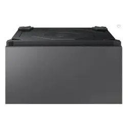
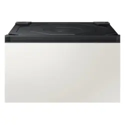
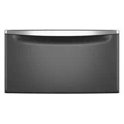
Pedestal consists of:
1 Elevated Base Pedestal
4 Leveling Leg Nuts
4 Leveling Legs
4 Rubber Feet
4 5/16 in. Cap Screw (2 in.)
4 5/16 in. Lock Washer
4 5/16 in. Nut
3 Hex Screw
1 Dryer Mounting Strap
2 5/16 in. Cap Screw (3.5 in.)
8 3/8 in. Flat Washer
2 1/2 in. Screw
1 Important Instructions
Tools required for this kit:
Installation Instructions for washer or dryer
Level
Crescent Wrench
5/16 in. Socket Driver
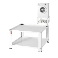
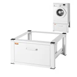
IMPORTANT: Elevated Base Pedestal is designed for
use with frontload washers or dryers only. Do not in-
stall on stack washer/dryer or stack dryer/dryer prod-
ucts. This pedestal is not designed for use with other
products.
Important Instructions
Subject: Installing Elevated Base Pedestal on Frontload Washers and Dryers
Use With: PDR108W, PDR108B, PDR108U, PDR108G, PDR108D, PDC106B,
PDC108B, PDC110B, PDC112B Elevated Base Pedestals
©
Copyright, Alliance Laundry Systems LLC -
DO NOT COPY or TRANSMIT
1 Form No. 7-04-47ENR14
February 2017
NOTE: Refer to the Installation Instructions that came
with the washer or dryer when uninstalling and rein-
stalling the washer or dryer.
WARNING
To reduce the risk of personal injury, two people are
required to lift the unit onto the pedestal.
W526
Homestyle Washer Installation
(PDR108W, PDR108B, PDR108U,
PDR108G, PDR108D Pedestal)
1. Disconnect electrical power to unit.
2. Turn off water supply and disconnect fill hoses.
3. Disconnect drain hose from drain receptacle.
4. Install the shipping brace before tipping washer to remove
leveling legs.
5. Remove existing leveling legs from bottom of unit. When tak-
ing off legs, tip unit back to get access to legs. This will re-
quire assistance.
IMPORTANT: DO NOT tip the washer onto its side.
Only tip toward front or back.
NOTE: Save leveling legs for future use.
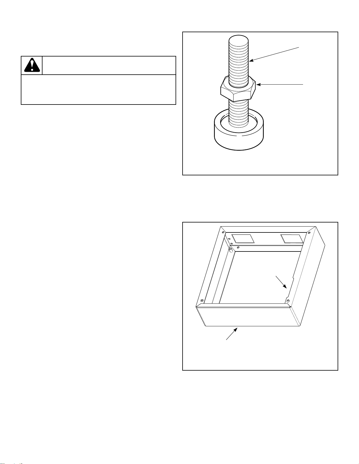
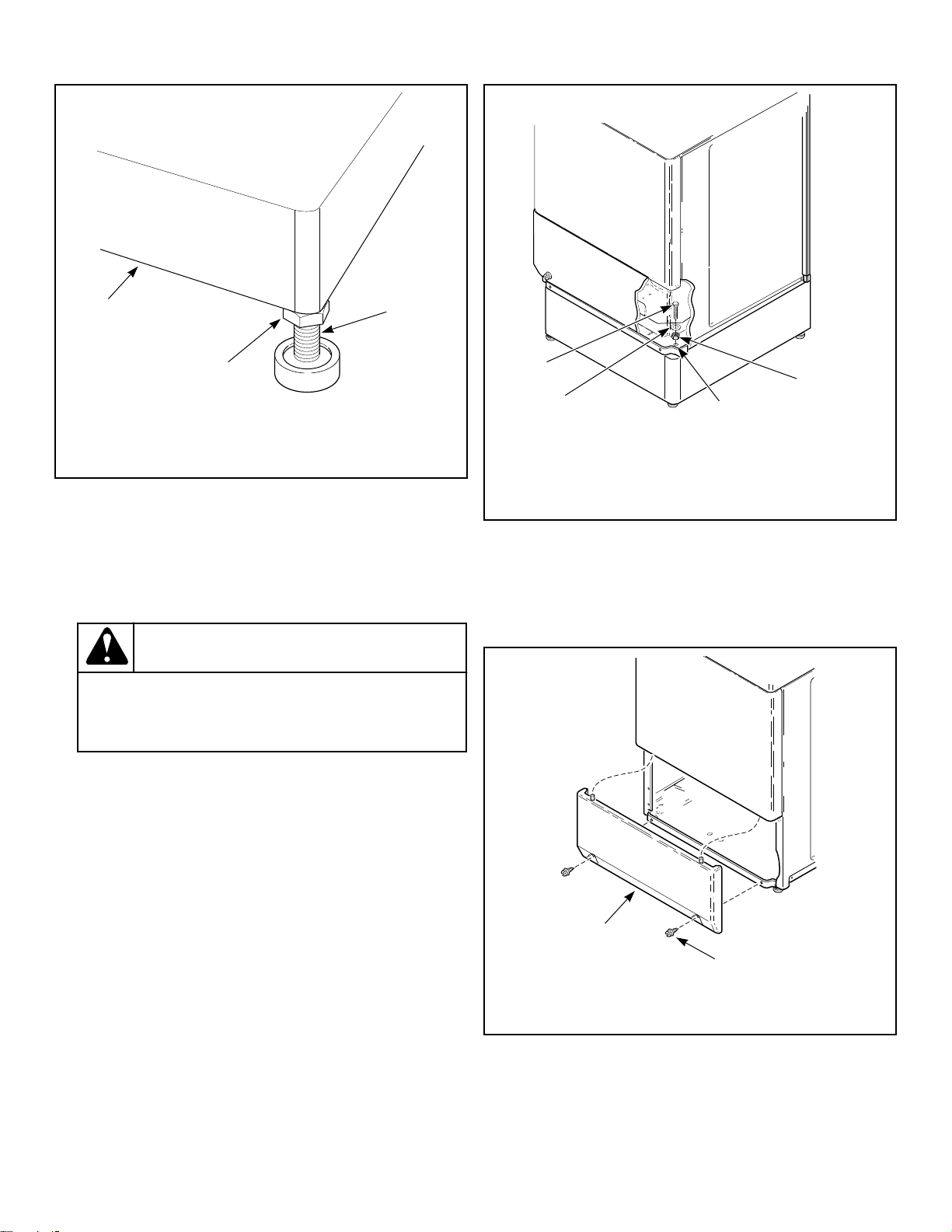
6. Install leveling legs included with pedestal onto bottom of
pedestal.
a. Place rubber feet on all four leveling legs.
b. Thread each nut down to within one inch of the bottom of
each leveling leg. Leave room for a wrench to fit for ad-
justing leg and tightening nut. Refer to Figure 1 .
FLW33K_SVG
1
2
1. Leveling Leg
2. Nut
Figure 1
c. Screw leveling legs with nuts into bottom flange of the
elevated base pedestal.
7. Place pedestal into desired final location. Position pedestal so
the notch is in the top right corner. Refer to Figure 2 .
FLW127K_SVG
2
1
1. Notch in Top Right Corner
2. Front of Pedestal
Figure 2
8. Level pedestal from front to back and from side to side by
screwing leveling legs into or out of pedestal. Refer to Figure
3 . Turn leg clockwise to lift or counterclockwise to lower.
©
Copyright, Alliance Laundry Systems LLC -
DO NOT COPY or TRANSMIT
2 Form No. 7-04-47ENR14
FLW34K_SVG
1
3
2
1. Pedestal
2. Tighten This Nut Against Bottom of Pedestal
3. Adjust Leveling Leg
Figure 3
9. Once pedestal is level, tighten the nuts installed in step 8 up
against bottom of pedestal. Refer to Figure 3 . Make sure to
hold leg when tightening nut.
10. Move pedestal into an open work area. You will need access
to back and front of unit to attach unit to pedestal.
WARNING
To reduce the risk of personal injury, two people
are required to lift the unit onto the pedestal.
W526
11. With proper help, tilt unit forward and lift. Carefully set unit
onto pedestal. Make sure front of unit is positioned to line up
with pedestal’s mounting holes. Refer to Figure 4 . Make sure
pedestal is square with front and back of unit.
FLW17K_SVG
1
2
4
3
1. Screw
2. Washer
3. Mounting Hole
4. Nut (Dryer only - acts as a spacer)
Figure 4
12. Gather contents of the parts bag.
13. Remove front access panel at the lower front of unit by re-
moving two screws from bottom edge of panel. Refer to Fig-
ure 5 .
FLW18K_SVG
1
2
1. Front Access Panel
2. Screw
Figure 5
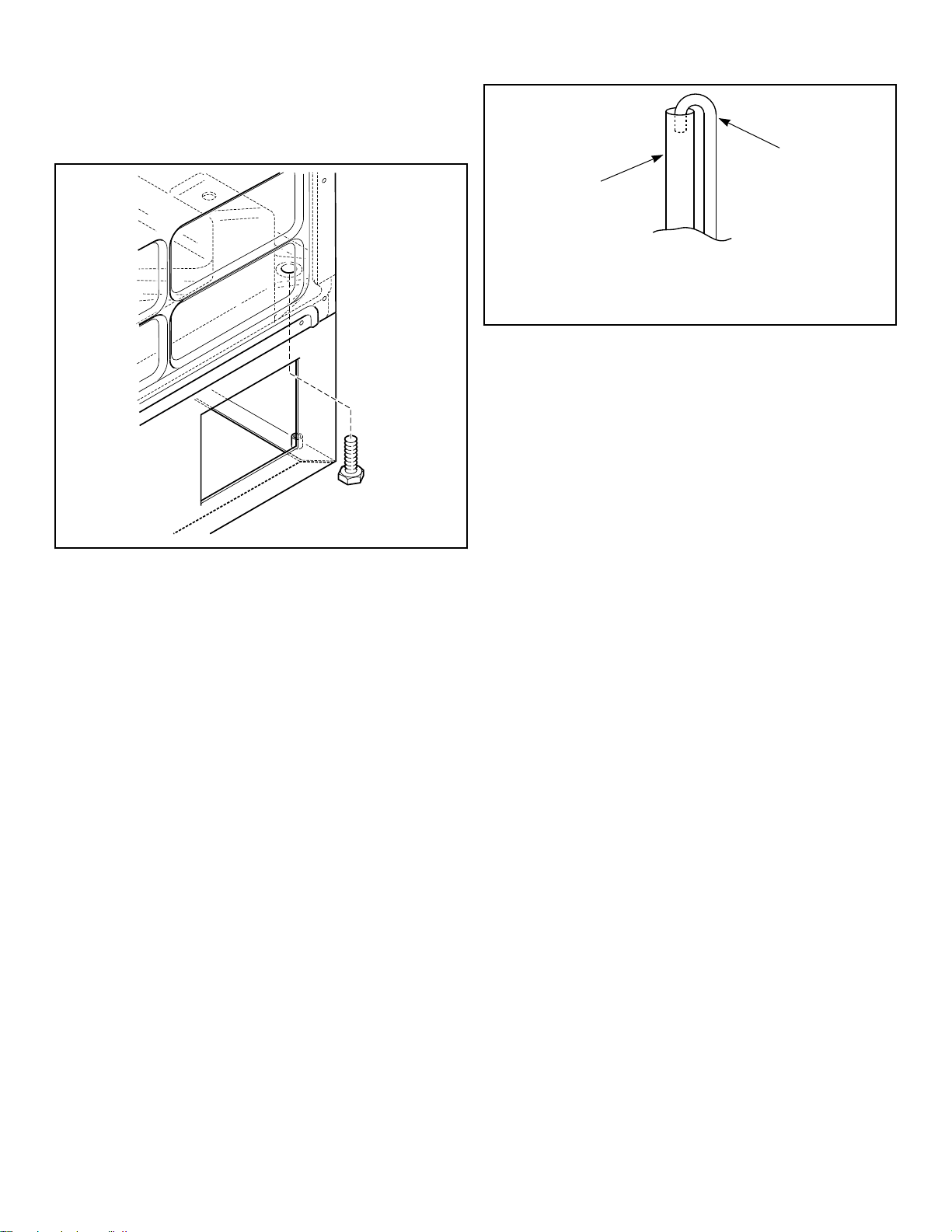
14. Attach washer to pedestal by placing two cap screws and
washers from inside of washer into threaded holes on front of
pedestal. Refer to Figure 4 .
©
Copyright, Alliance Laundry Systems LLC -
DO NOT COPY or TRANSMIT
3 Form No. 7-04-47ENR14
15. Attach washer to pedestal by placing two 1/2-inch screws
from back of pedestal into threaded holes on back of pedestal.
Refer to Figure 6 . After partially installing all four, tighten
all four screws.
FLW2398N
FLW129K_SVG
Figure 6
16. Remove the shipping brace from front of machine and the two
bolts from rear of machine. Verify all shipping parts have
been removed.
17. Reinstall front access panel.
18. Move unit with pedestal into desired location. Position rear of
elevated base pedestal to allow sufficient room for reinstalla-
tion. Refer to installation instructions supplied with unit for
proper spacing and clearance.
19. Check if unit is level. If needed, make final adjustment to lev-
eling legs on pedestal.
20. Follow Installation Instructions from unit to finish installing
the unit.
21. Drain Hose Models - Reattach drain hose to drain receptacle.
IMPORTANT: Add height of pedestal to recommend-
ed standpipe height (24 to 36 inches [61 to 91.44
cm]). Verify that standpipe drain is within new
range. Raise standpipe as needed so drain hose fits
at an appropriate depth. Refer to Figure 7 .
FLW54K_SVG
2
1
1. Standpipe
2. Drain Hose
Figure 7
22. Gravity Drain Models - Connect drain fitting to vented drain
system using a flexible connection (obtain locally). Inside di-
ameter of fitting is 1.53 in. [39 mm] and outside diameter is
1.66 in. [42 mm].
NOTE: Water must flow downward from washer to
drain system.
23. Reattach fill hoses and turn on water supply.
24. Reconnect electrical power to unit.
Commercial Washer Installation
(PDC106B, PDC108B, PDC110B,
PDC112B Pedestals)
1. Disconnect electrical power to unit.
2. Turn off water supply and disconnect fill hoses.
3. Disconnect drain hose from drain receptacle.
4. Install leveling legs included with pedestal onto bottom of
pedestal.
NOTE: Alternatively, this pedestal may be bolted to
a concrete or wooden structure using industry
standard mounting methods.
a. Place rubber feet on all four leveling legs.
b. Thread each nut down to within one inch of the bottom of
each leveling leg. Leave room for a wrench to fit for ad-
justing leg and tightening nut. Refer to Figure 1 .
c. Screw leveling legs with nuts into bottom flange of pedes-
tal.
5. Place pedestal into desired location. Front of pedestal has two
bolt holes on top flange. Refer to Figure 8 .
©
Copyright, Alliance Laundry Systems LLC -
DO NOT COPY or TRANSMIT
4 Form No. 7-04-47ENR14
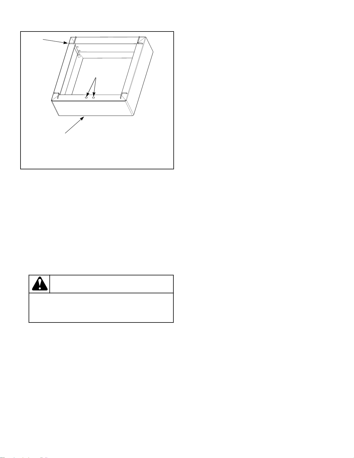
FLW73K_SVG
2
1
3
1. Mounting Bracket
2. Front of Pedestal
3. Bolt Holes
Figure 8
6. Level pedestal from front to back and from side to side by
screwing leveling legs into or out of pedestal. Refer to Figure
3 . Turn leg clockwise to lift or counterclockwise to lower.
7. Once pedestal is level, tighten the nuts installed in step 6 up
against bottom of pedestal. Refer to Figure 3 . Make sure to
hold leg when tightening nut.
8. If installing two or more pedestals in a row, they may be bolt-
ed together. Use four 5/16 inch cap screws and nuts included
in kit. Place two 3/8 inch flat washers included in kit between
pedestals to allow for unit clearance.
9. Make sure washer is level. Adjust leveling legs on washer if
necessary.
WARNING
To reduce the risk of personal injury, two people
are required to lift the unit onto the pedestal.
W526
10. With proper help, tilt washer forward and lift. Carefully set
washer onto pedestal, placing washer’s feet into pedestal’s
mounting brackets. Refer to Figure 8 . Make sure pedestal is
square with front and back of washer.
11. Remove front access panel at lower front of washer by re-
moving two screws from bottom edge of panel. Refer to Fig-
ure 5 .
12. Install two 5/16 inch cap screws included with pedestal
through washer’s shipping bracket holes and into pedestal.
Refer to Figure 8 .
13. Reinstall front access panel.
14. Check if unit is level. If needed, make final adjustment to lev-
eling legs on pedestal.
15. Follow Installation Instructions from unit to finish installing
the unit.
16. Drain Hose Models -Reattach drain hose to drain receptacle.
IMPORTANT: Add height of pedestal to recommend-
ed standpipe height (24 to 36 inches [61 to 91.44
cm]). Verify that standpipe drain is within new
range. Raise standpipe as needed so drain hose fits
at an appropriate depth. Refer to Figure 7 .
17. Gravity Drain Models - Connect drain fitting to vented drain
system using a flexible connection (obtain locally). Inside di-
ameter of fitting is 1.53 in. [39 mm] and outside diameter is
1.66 in. [42 mm].
NOTE: Water must flow downward from washer to
drain system.
18. Reattach fill hoses and turn on water supply.
19. Reconnect electrical power to unit.
Homestyle Dryer Installation
(PDR108W, PDR108B, PDR108U,
PDR108G, PDR108D Pedestal)
1. Disconnect electrical power to unit.
2. Disconnect dryer vent.
3. On gas dryers, disconnect gas from dryer.
4. Remove existing leveling legs from bottom of unit. When tak-
ing off legs, tip unit back to get access to legs. This will re-
quire assistance.
NOTE: Save leveling legs for future use.
5. Remove four leveling legs, nuts and rubber feet from parts
bag included with pedestal.
6. Place rubber feet on all four leveling legs.
7. Thread each nut down to within one inch of the bottom of
each leveling leg. Leave room for a wrench to fit for adjusting
leg and tightening nut. Refer to Figure 1 .
8. Screw leveling legs with nuts into bottom flange of the elevat-
ed base pedestal.
9. Place pedestal into desired final location. Position pedestal so
the notch is in the top right corner. Refer to Figure 2 .
10. Level pedestal from front to back and from side to side by
screwing leveling legs into or out of pedestal. Refer to Figure
3 . Turn leg clockwise to lift or counterclockwise to lower.
11. Once pedestal is level, tighten the nuts installed in step 7 up
against bottom of pedestal. Refer to Figure 3 . Make sure to
hold leg when tightening nut.
12. Move pedestal into an open work area. You will need access
to back and front of unit to attach unit to pedestal.
©
Copyright, Alliance Laundry Systems LLC -
DO NOT COPY or TRANSMIT
5 Form No. 7-04-47ENR14
WARNING
To reduce the risk of personal injury, two people
are required to lift the unit onto the pedestal.
W526
13. With proper help, tilt unit forward and lift. Carefully set unit
onto pedestal. Make sure front of unit is positioned to line up
with pedestal’s mounting holes. Refer to Figure 4 . Make sure
pedestal is square with front and back of unit.
14. Gather contents of the parts bag.
15. Remove front access panel at the lower front of unit by re-
moving two screws from bottom edge of panel. Refer to Fig-
ure 5 .
16. Attach dryer to pedestal by placing two cap screws, washers
and nuts from inside front of unit into threaded holes on ped-
estal. Nuts act as spacers to keep screw head above dryer base
leg holes. Refer to Figure 4 . Tighten screws after partially in-
stalling both.
NOTE: Remaining two screws, washers and nuts are
not required to attach dryer to pedestal.
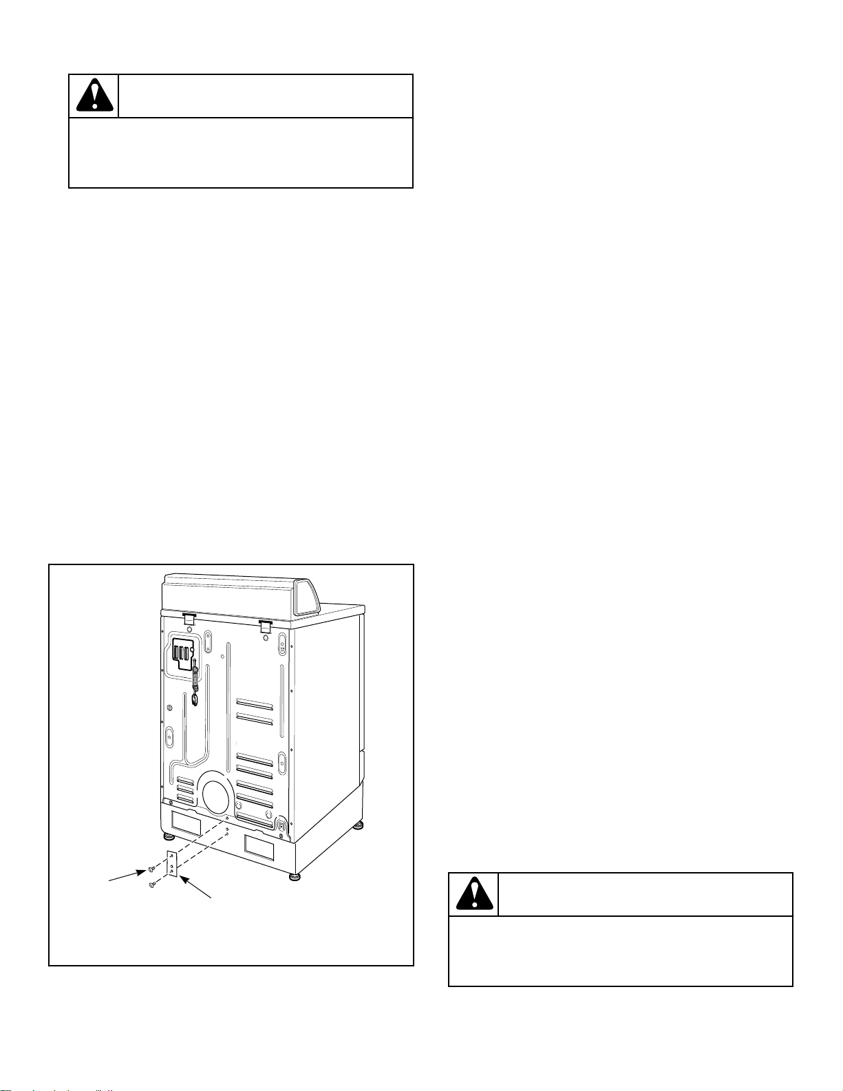
17. Attach strap included in parts bag to dryer cabinet rear panel
and to center back of pedestal. Remove one screw from mid-
dle of dryer rear panel. Refer to Figure 9 . Reattach screw
with strap using long slot hole. Do not tighten yet. Attach
strap to back of pedestal using two screws. Refer to Figure 9 .
Tighten all screws.
FLW128K_SVG
1
2
1. Screw From Dryer Rear Panel
2. Strap
Figure 9
18. Reinstall front access panel.
19. Move unit with pedestal into desired location. Position rear of
elevated base pedestal to allow sufficient room for reinstalla-
tion. Refer to installation instructions supplied with unit for
proper spacing and clearance.
20. Check if unit is level. If needed, make final adjustment to lev-
eling legs on pedestal.
21. Follow Installation Instructions from unit to finish installing
the unit.
22. Reattach dryer vent.
23. On gas dryers, reattach gas to dryer.
24. Reconnect electrical power to unit.
Commercial Dryer Installation
(PDC106B, PDC108B, PDC110B,
PDC112B Pedestals)
1. Disconnect electrical power to unit.
2. Disconnect dryer vent.
3. On gas dryers, disconnect gas from dryer.
4. Remove four leveling legs, nuts and rubber feet from parts
bag included with pedestal.
5. Place rubber feet on all four leveling legs.
6. Thread each nut down to within one inch of the bottom of
each leveling leg. Leave room for a wrench to fit for adjusting
leg and tightening nut. Refer to Figure 1 .
7. Screw leveling legs with nuts into bottom flange of the elevat-
ed base pedestal.
NOTE: Alternatively, this pedestal may be bolted to
a concrete or wooden structure using industry
standard mounting methods.
8. Place pedestal into desired final location. Front of pedestal
has two bolt holes on top, front flange. Refer to Figure 8 .
9. Level pedestal from front to back and from side to side by
screwing leveling legs into or out of pedestal. Refer to Figure
3 . Turn leg clockwise to lift or counterclockwise to lower.
10. Once pedestal is level, tighten the nuts installed in step 6 up
against bottom of pedestal. Refer to Figure 3 . Make sure to
hold leg when tightening nut.
11. If installing two or more pedestals in a row, they may be bolt-
ed together. Use four 5/16 inch cap screws and nuts included
in kit. Place two 3/8 inch flat washers included in kit between
pedestals to allow for unit clearance.
WARNING
To reduce the risk of personal injury, two people
are required to lift the unit onto the pedestal.
W526
©
Copyright, Alliance Laundry Systems LLC -
DO NOT COPY or TRANSMIT
6 Form No. 7-04-47ENR14

12. Make sure dryer is level. Adjust leveling legs on dryer if nec-
essary.
13. With proper help, tilt dryer forward and lift. Carefully set unit
onto pedestal, placing unit’s feet into pedestal’s mounting
brackets. Refer to Figure 8 . Make sure pedestal is square
with front and back of unit.
14. Attach strap included in parts bag to dryer cabinet rear panel
and to center back of pedestal. Remove one screw from mid-
dle of dryer rear panel. Refer to Figure 9 . Reattach screw
with strap using long slot hole. Do not tighten yet. Attach
strap to back of pedestal using two screws. Refer to Figure 9 .
Tighten all screws.
15. Check if unit is level. If needed, make final adjustment to lev-
eling legs on pedestal.
16. Follow Installation Instructions from unit to finish installing
the unit.
17. Reattach dryer vent.
18. On gas dryers, reattach gas to dryer.
19. Reconnect electrical power to unit.
©
Copyright, Alliance Laundry Systems LLC -
DO NOT COPY or TRANSMIT
7 Form No. 7-04-47ENR14