
THANK YOU for purchasing this high-quality product. Register your new range at www.whirlpool.com. In Canada, register your range
at www.whirlpool.ca.
For future reference, please make a note of your product model and serial numbers. These can be located on the oven frame behind the
top right side of the oven door.
Model Number__________________________________________ Serial Number__________________________________________
Para una versión de estas instrucciones en español, visite www.whirlpool.com.
Deberá tener a mano el número de modelo y de serie, que están ubicados en el marco del horno, detrás del lado derecho superior de la
puerta del horno.
Table of Contents
USER INSTRUCTIONS
GAS RANGE
W11085353A
RANGE SAFETY .............................................................................2
The Anti-Tip Bracket ....................................................................3
KEY USAGE TIPS ...........................................................................4
AquaLift
®
Self-Cleaning Technology ............................................4
Surface Temperatures ..................................................................4
Preheating ....................................................................................4
Surface Burners ...........................................................................4
FEATURE GUIDE ............................................................................5
Touch Panel .................................................................................. 6
Display ..........................................................................................6
Display Navigation .......................................................................6
Cooking Methods ......................................................................... 6
Assisted Cooking .........................................................................8
Favorites .......................................................................................8
Tools .............................................................................................8
More Modes .................................................................................9
COOKTOP ....................................................................................10
Surface Burners .........................................................................10
Surface Grates ...........................................................................11
Burner Size .................................................................................11
Cookware ...................................................................................12
Home Canning ...........................................................................12
OVEN .............................................................................................13
Aluminum Foil .............................................................................13
Positioning Racks and Bakeware ..............................................13
Oven Vent ...................................................................................14
Baking and Roasting ..................................................................14
Broiling........................................................................................14
Convection Cooking ..................................................................15
Oven Light ..................................................................................15
Cook Time ..................................................................................15
RANGE CARE ...............................................................................16
Clean Cycle ................................................................................16
General Cleaning ........................................................................17
TROUBLESHOOTING ..................................................................18
ACCESSORIES .............................................................................20
WARRANTY ..................................................................................21
2
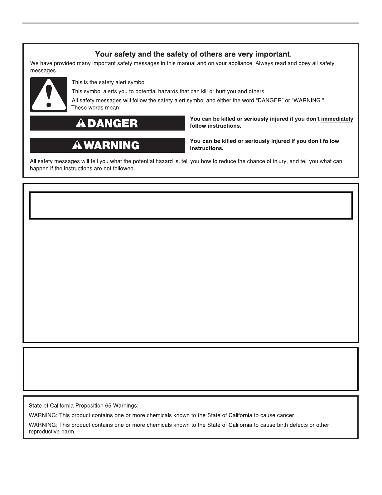
RANGE SAFETY
WARNING: If the information in these instructions is not followed exactly, a fire or
explosion may result causing property damage, personal injury or death.
– Do not store or use gasoline or other flammable vapors and liquids in the vicinity of this
or any other appliance.
– WHAT TO DO IF YOU SMELL GAS:
•
Do not try to light any appliance.
•
Do not touch any electrical switch.
•
Do not use any phone in your building.
•
Immediately call your gas supplier from a neighbor's phone. Follow the gas supplier's
instructions.
•
If you cannot reach your gas supplier, call the fire department.
–
Installation and service must be performed by a qualified installer, service agency or
the gas supplier.
WARNING: Gas leaks cannot always be detected by smell.
Gas suppliers recommend that you use a gas detector approved by UL or CSA.
For more information, contact your gas supplier.
If a gas leak is detected, follow the “What to do if you smell gas” instructions.
3
The Anti-Tip Bracket
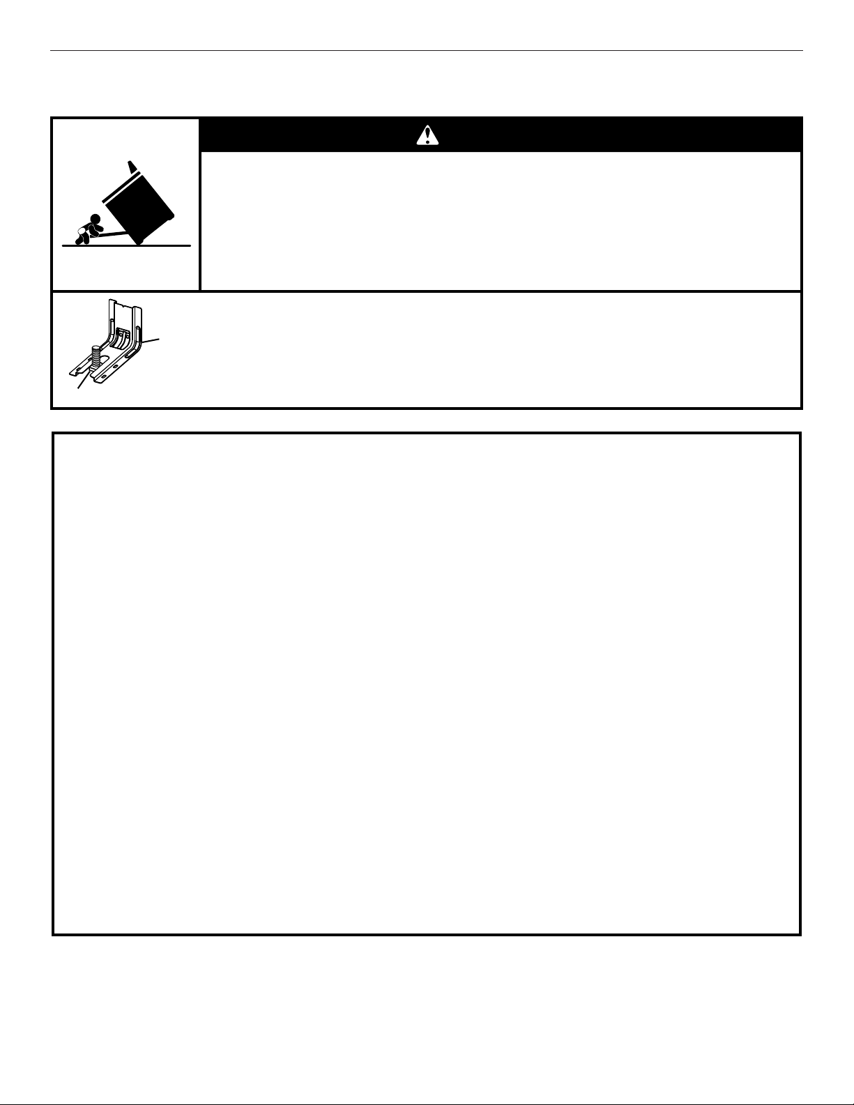
The range will not tip during normal use. However, the range can tip if you apply too much force or weight to the open door without the
anti-tip bracket fastened down properly.
Tip Over Hazard
A child or adult can tip the range and be killed.
Verify the anti-tip bracket has been properly installed and engaged per installation instructions.
Re-engage anti-tip bracket if range is moved.
Do not operate range without anti-tip bracket installed and engaged.
Failure to follow these instructions can result in death or serious burns to children and adults.
To verify the anti-tip bracket is installed and engaged:
• Slide range forward.
• Look for the anti-tip bracket securely attached to floor or wall.
• Slide range back so rear range foot is under anti-tip bracket.
• See installation instructions for details.
WARNING
Anti-Tip
Bracket
Range Foot
SAVE THESE INSTRUCTIONS
IMPORTANT SAFETY INSTRUCTIONS
WARNING: To reduce the risk of fire, electrical shock,
injury to persons, or damage when using the range, follow
basic precautions, including the following:
■
WARNING: TO REDUCE THE RISK OF TIPPING OF
THE RANGE, THE RANGE MUST BE SECURED BY
PROPERLY INSTALLED ANTI-TIP DEVICES. TO CHECK
IF THE DEVICES ARE INSTALLED PROPERLY, SLIDE
RANGE FORWARD, LOOK FOR ANTI-TIP BRACKET
SECURELY ATTACHED TO FLOOR OR WALL, AND
SLIDE RANGE BACK SO REAR RANGE FOOT IS UNDER
ANTI-TIP BRACKET.
■
WARNING:
NEVER use this appliance as a space
heater to heat or warm the room. Doing so may result in
carbon monoxide poisoning and overheating of the oven.
■
WARNING:
NEVER cover any slots, holes or passages
in the oven bottom or cover an entire rack with materials
such as aluminum foil. Doing so blocks air flow through the
oven and may cause carbon monoxide poisoning.
Aluminum foil linings may also trap heat, causing a fire
hazard.
■ CAUTION: Do not store items of interest to children in
cabinets above a range or on the backguard of a range –
children climbing on the range to reach items could be
seriously injured.
■
Proper Installation – The range, when installed, must be
electrically grounded in accordance with local codes or, in
the absence of local codes, with the
National Electrical
Code, ANSI/NFPA 70
. In Canada, the range must be
electrically grounded in accordance with Canadian
Electrical Code. Be sure the range is properly installed and
grounded by a qualified technician.
■
This range is equipped with a three-prong grounding plug
for your protection against shock hazard and should be
plugged directly into a properly grounded receptacle. Do
not cut or remove the grounding prong from this plug.
■ Disconnect power before servicing.
■
Injuries may result from the misuse of appliance doors or
drawers such as stepping, leaning, or sitting on the doors
or drawers.
■
Maintenance – Keep range area clear and free from
combustible materials, gasoline, and other flammable
vapors and liquids.
■ Storage in or on the Range – Flammable materials should
not be stored in an oven or near surface units.
■
Top burner flame size should be adjusted so it does not
extend beyond the edge of the cooking utensil.
For self-cleaning ranges –
■
Before Self-Cleaning the Oven – Remove broiler pan and
other utensils. Wipe off all excessive spillage before
initiating the cleaning cycle.
4
KEY USAGE TIPS
AquaLift
®
Self-Cleaning Technology
AquaLift
®
Self-Cleaning Technology is a first-of-its-kind
cleaning solution designed to minimize the time, temperature,
and odors that ordinarily come with traditional self-cleaning
methods. With AquaLift
®
Self-Cleaning Technology, an innovative
coating on the interior of the oven is activated with heat and
water to release baked-on soil. To use AquaLift
®
Self-Cleaning
Technology, simply wipe out loose debris, pour water into the
oven bottom, and run the AquaLift
®
Self-Cleaning cycle. When
the cycle finishes in under 1 hour at a lower temperature than
in traditional self-cleaning methods, just wipe out the remaining
water and loose debris. See the “Clean Cycle” section for more
detailed instructions. For additional information, frequently
asked questions and videos on using AquaLift
®
Self-Cleaning
Technology, visit our website at http://whirlpoolcorp.com/
aqualift.
Surface Temperatures
When the range is in use, all range surfaces may become hot,
such as the knobs and oven door.
Warming or Storage Drawer
When the oven is in use, the drawer may become hot. Do not
store plastics, cloth, or other items that could melt or burn in
the drawer.
Oven Vent
The oven vent releases hot air and moisture from the oven, and
should not be blocked or covered. Do not set plastics, paper,
or other items that could melt or burn near the oven vent.
Preheating
When beginning a Bake, Convect Bake, or Convect Roast cycle,
the oven will begin preheating after Start is pressed. The oven
will take approximately 12 to 15 minutes to reach 350°F (177°C)
with all of the oven racks provided with your oven inside the
oven cavity. Higher temperatures will take longer to preheat.
The preheat cycle rapidly increases the oven temperature. The
actual oven temperature will go above your set temperature to
offset the heat lost when your oven door is opened to insert food.
This ensures that when you place your food in the oven, the
oven will begin at the proper temperature. Insert your food when
the preheat tone sounds. Do not open the door during preheat
before the tone sounds.
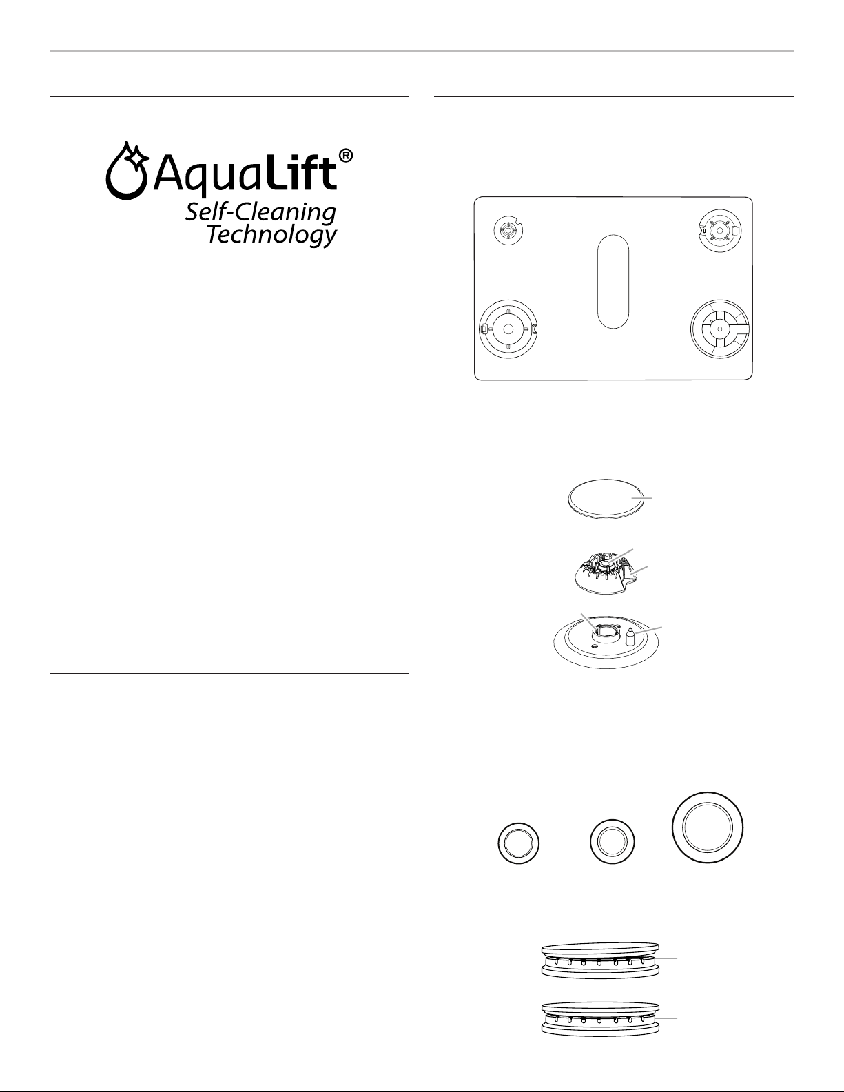
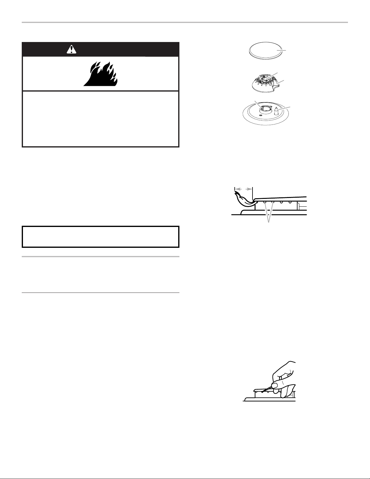
Surface Burners
The burner bases and caps must be properly positioned before
cooking. Your range comes with three sizes of burners and
caps. Each round burner base is marked with a letter indicating
the burner size. Align the burner bases as shown in the following
illustration:
Align the gas tube opening in the burner base with the orifice
holder on the cooktop and the igniter electrode with the notch
in the burner base.
Each round burner cap is marked with a letter indicating the
burner size. Place the burner caps on the appropriate burner
bases.
AUX
SR
UR
Small cap (AUX)
Medium cap (SR) X-Large (UR)
Burner caps should be level when properly positioned. If burner
caps are not properly positioned, surface burners will not light.
The burner cap should not rock or wobble when properly aligned.
A
D
EB
A. Small (S)
B. Large (L)
C. Oval D. Medium (M)
E. Large (L)
C
A. Small (AUX)
B. X-Large (UR)
C. Medium D. Medium (SR)
E. Wok
A
B
C
D
E
A. Burner cap
B. Gas tube opening
C. Burner base
D. Igniter electrode
E. Orifice holder
A
B
A. Incorrect
B. Correct
5
FEATURE GUIDE
These instructions cover several models. Your model may have some or all of the items listed. Refer to these instructions or the
Frequently Asked Questions (FAQs) section of our website at www.whirlpool.com for more detailed instructions. In Canada, visit our
website at www.whirlpool.ca.
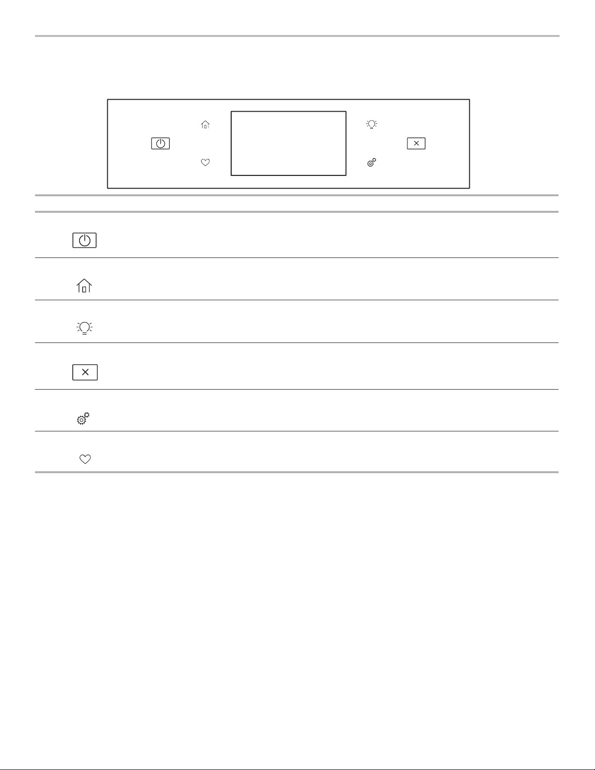
Keypad Feature Instructions
Oven Power Oven Function
Power
The Oven Power keypad begins oven function and wakes it from sleep mode.
Home Home Screen
If pressed once, it enables the user to return to the “Cooking Methods” and “Assisted
Cooking” screen. If pressed twice, the time of day is displayed.
Oven Light Oven Cavity
Light
The oven light is controlled by a keypad on the oven control panel. While the oven door
is closed, press the oven light keypad to turn the light on and off. When the oven door is
opened, the oven light will automatically turn on.
Oven Cancel Oven Function
Cancel
The Oven Cancel keypad stops any oven function except the Clock, Timer, and Control Lock.
Tools Oven Use
Functions
Enables you to personalize the audible tones and oven operation to suit your needs. See the
“Tools” and “More Modes” section.
Favorites Favorites Screen
The Favorites keypad allows the user to save and access the cycles that they use on a
frequent basis.
6
Touch Panel
The touch panel houses the control menu and function controls.
The touch keypads are very sensitive and require only a light
touch to activate.
Scroll up, down, left, or right to explore the different options and
features.
For more information about the individual controls, see their
respective sections in this manual.
Display
The display is for both the menu and oven function controls. The
touchscreen allows you to scroll through the oven menus. The
display is very sensitive and requires only a light touch to activate
and control.
When the oven is in use, the display will show the clock, mode,
oven temperature, kitchen timer, and oven timer, if set. If the oven
timer is not set, you can set it from this screen.
After approximately 2 minutes of inactivity, the display will go
into sleep mode and the display will dim. When the oven is in
operation, the display will remain bright.
During use, the display will show menus and the appropriate
selections for the options being chosen.
Display Navigation
If the oven is off, touch the Home keypad to activate the menu.
From this screen, all automatic cooking programs can be
activated, all manual cooking programs can be set, options
can be adjusted, and instructions, preparation, and tips can be
accessed.
Cooking Methods
The Cooking Methods keypad allows users to select one of the cooking methods below according to their cooking needs:
■ Bake
■ Broil
■ Convect Bake
■ Convect Broil
■ Convect Roast
■ Keep Warm
To Use:
1. Touch the Home keypad.
2. Select the Cooking methods keypad.
3. Select desired cooking method.
WARNING
Food Poisoning Hazard
Do not let food sit in oven more than one hour before
or after cooking.
Doing so can result in food poisoning or sickness.
Cooking Method Feature Instructions
BAKE Baking and
roasting
1. Select BAKE.
2. Select the desired temperature by scrolling left to right or manually by selecting the grid in
the upper right corner and entering the bake temperature into the keypad.
3. Select START to begin preheating. A tone will sound when preheating is complete.
4. (Optional) To quickly preheat the oven, see the “Rapid” section for more information in this
section.
5. Press the Cancel keypad when finished.
BROIL Broiling
1. Select BROIL.
2. Select the desired temperature by scrolling left to right or manually by selecting the grid in
the upper right corner and entering the broil temperature into the keypad.
3. Select START to begin broiling.
4. Press the Cancel keypad when finished.

7
Cooking Method Feature Instructions
CONVECT BAKE Convection
baking
1. Select CONVECT BAKE.
2. Select the desired temperature by scrolling left to right or manually by selecting the grid in
the upper right corner and entering the convect bake temperature into the keypad.
3. Select START to begin preheating. There will be a beep when preheating is complete.
4. (Optional) To quickly preheat the oven, see the “Rapid” section for more information in this
section.
5. Press the Cancel keypad when finished.
For more information, see the “Convection Cooking” section.
CONVECT BROIL Convection
broiling
1. Select CONVECT BROIL.
2. Select the desired temperature by scrolling left to right or manually by selecting the grid in
the upper right corner and entering the convect broil temperature into the keypad.
3. Select START.
4. Press the Cancel keypad when finished.
For more information, see the “Convection Cooking” section.
CONVECT
ROAST
Convection
roasting
1. Select CONVECT ROAST.
2. Select the desired temperature by scrolling left to right or manually by selecting the grid in
the upper right corner and entering the convect roast temperature into the keypad.
3. Select START.
4. Press the Cancel keypad when finished.
For more information, see the “Convection Cooking” section
KEEP WARM Keep warm
Food must be at serving temperature before placing it in the warmed oven.
1. Select KEEP WARM.
2. Select the desired temperature by scrolling left to right or manually by selecting the grid in
the upper right corner and entering the desired temperature into the keypad.
3. Press START.
4. Press the Cancel keypad when finished.
RAPID Rapid oven
preheating
Provides the fastest preheat time for the Bake function. Rapid Preheat is preset to off.
1. Select RAPID to toggle between turning the rapid preheat off and on.
2. The current setting will be displayed.
IMPORTANT: This feature should only be used for one-rack baking. Unused racks should be
removed prior to Rapid Preheat. A standard rack should be used for Rapid Preheat.
If preheating for the Bake cycle has already started, Rapid Preheat may be started by selecting
RAPID.
START TIME Delayed start
Start Time is used to enter the starting time for an oven function with a delayed start. Start Time
should not be used for foods such as breads and cakes because they may not bake properly.
COOK TIME Timed cooking
Cook Time allows the oven to be set to turn on, cook for a set length of time, and/or shut off
automatically.

8
Assisted Cooking
To reduce cooking preparation steps, this oven features Frozen
Bake™ technology that skips the preheat for some frozen food
categories. These include: Pizza, Lasagna, Nuggets/fries, Pies,
and Meal. Food should go in the oven immediately.
Scroll through the Assisted Cooking menu until the desired food
selection is reached.
Follow the prompts on the screen to customize the settings for
Assisted Cooking.
Favorites
The Favorites feature stores the oven mode and temperature for
your favorite recipes.
NOTE: A select set of Favorites and suggestions may be
automatically shown on the Home screen based on your meal
times.
To save a recipe, select the Favorites keypad, and follow the
prompts on the screen to customize your favorites.
Add an image or name to the favorite to customize it to your
preferences.
Tools
The Tools keypad allows you access to functions and
customization options for your oven. These tools allow you to set
the clock, change the oven temperature between Fahrenheit and
Celsius, turn the audible signals and prompts on and off, adjust
the oven calibration, change the language, and more.
Select the Tools keypad to view the Tools features.
See the “More Modes” section for more information.
Tool Notes
Remote Enable
Select Remote Enable to enable the ability to
utilize the Whirlpool
®
app.
NOTE: Remote Enable turns off when the
door is opened. It needs to be re-enabled
each time it is going to be used.
Kitchen Timer
Set a kitchen timer by manually entering the
desired time into the keypad.
1. Select Kitchen Timer.
2. Manually input the time to the desired
timer length.
3. Select Start.
4. Select the Cancel keypad to end the
Kitchen Timer.
Light
Select Light to turn the light on and off.
When the oven door is opened, the oven
light will automatically turn on.
Self-Clean
See the “Range Care” section
Mute
Select Mute to mute or unmute the
oven sounds.
Control Lock
The Control Lock locks the control panel
keypads to avoid unintended use of the
oven(s). If set before the power failure
occurs, the Control Lock keypad will remain
set after a power failure. When the control
is locked, only the Oven Power, Tools, and
Oven Light keypads will function.
The Control Lock is preset unlocked, but can
be locked.
To Lock or Unlock Control:
1. Check that the oven is off.
2. Select the “Control Lock” keypad.
3. “Control Lock” will display.
4. Scroll up to unlock.
No keypads will function with the controls
locked. The cooktop functions are not
affected by the oven control lockout.

9
More Modes
Sabbath Mode
For guidance on usage and a complete list of models with
Sabbath Mode, visit www.star-k.org.
The Sabbath Mode sets the oven to remain on in a bake setting
until disabled.
When the Sabbath Mode is activated, only the Bake cycle will
operate. All other cooking and cleaning cycles are disabled. No
tones will sound, and the displays will not indicate temperature
changes. When the oven door is opened or closed, the oven light
will not turn on or off, and the heating elements will not turn on or
off immediately.
If a cook timer is set, the countdown will not appear. The timer
will appear frozen at the set time.
NOTE: If a power failure happens while Sabbath Mode is running,
the oven will show Sabbath Mode is on, but the Bake cycle will
not be on. If the oven door is opened during this time, the oven
light will turn on.
To Enable and Activate Sabbath Mode:
1. Press the Tools keypad.
2. Select More Modes.
3. Select Sabbath Mode.
4. Press Sabbath Mode again to enable Sabbath Mode
(Sabbath Mode is preset to Off).
5. Select Yes if you would like to have your oven on and baking
during the Sabbath.
6. Enter the desired temperature.
(Optional) For timed cooking in Sabbath Mode, Press ADD
A COOK TIME for the selected oven, Enter the desired cook
time and then press NEXT.
7. Select Start.
To Disable and Exit Sabbath Mode:
Press and hold the display screen for three seconds.
To Adjust Temperature:
1. Press the +/- 25 on the display screen to select the new
temperature.
NOTE: The temperature adjustment will not appear on the
display, and no tones will sound.
Temperature Calibration
IMPORTANT: Do not use a thermometer to measure the oven
temperature. Elements will cycle on and off as needed to
maintain a consistent temperature but may run slightly hot or cool
at any point in time due to this cycling. Opening the oven door
will affect cycling of the elements and impact the temperature.
The oven provides accurate temperatures and has been
thoroughly tested at the factory. However, it may cook faster
or slower than your previous oven, causing baking or browning
differences. If necessary, the temperature calibration can be
adjusted in either Fahrenheit or Celsius.
A minus sign means the oven will be cooler by the displayed
amount. The absence of a minus sign means the oven will be
warmer by the displayed amount. Use the following chart as
a guide.
NOTE: The oven display will continue to show the original
set temperature and will not reflect the calibration offset. For
example, if set to 350° (177°C) and calibrated to -20, the display
will continue to show 350° (177°C).
Adjust the oven temp up to (+,-) 30° (-18°C)
It is recommended to make changes in 5°F (3°C) increments until
desired results are achieved.
To Adjust Oven Temperature Calibration:
1. Press the Tools keypad.
2. Select More Modes.
3. Select Temperature Calibration.
4. Scroll from left to right to increase or decrease the
temperature.
Preferences
Times and Dates
Set time and date preferences.
■ Your Meal Times: Adjust when breakfast/lunch/dinner is
shown
■ Time
■ Date
■ Time Format (AM/PM vs 24 Hour [Military Time])
NOTE: If user is connected to Wifi, time and date will be set
automatically.
Sound Volume
Set sound volume preferences.
■ Timers and Alerts
■ Buttons and Effects
Display Settings
Set the screen brightness.
■ Display Brightness
Regional
Set regional preferences.
■ Language: English, Spanish, or French
■ Temperature Units: Fahrenheit and Celsius.
WiFi
■ Connect to Network: Download the Whirlpool
®
App from the
app store on your mobile phone. See the Connectivity Setup
sheet for more detailed instructions.
■ SAID Code: The SAID code is used to sync a smart device
with your appliance. Enter the SAID code in the Whirlpool
®
App.
■ MAC Address: MAC Address is displayed for the WiFi
module.
■ WiFi Radio: Turn WiFi on or off.
Info
■ Service and Support: Displays model number, Customer
Support contact info, and Diagnostics.
■ Store Demo Mode: Select Store Demo Mode to toggle
Demo mode off and on.
■ Restore Factory: This will restore your product to the original
factory default settings.
■ WiFi Terms and Conditions: www.whirlpool.com/connect
■ Software Terms and Conditions
10
COOKTOP
Electric igniters automatically light the surface burners
when control knobs are turned to Ignite.
Before setting a control knob, place filled cookware on
the grate. Do not operate a burner using empty cookware
or without cookware on the grate.
To Use:
1. Push in and turn knob counterclockwise to Ignite.
All surface burners will click. Only the burner with the
control knob turned to Ignite will produce a flame.
2. Turn knob to anywhere between HIGH and LOW.
Power Failure
In case of prolonged power failure, the surface burners can
be lit manually. Hold a lit match near a burner, and then turn
knob counterclockwise to Ignite. After burner lights, turn
knob to setting.
Surface Burners
IMPORTANT: Do not obstruct the flow of combustion
and ventilation air around the burner grate edges.
Burner Cap: Always keep the burner cap in place when using
a surface burner. A clean burner cap will help avoid poor ignition
and uneven flames. Always clean the burner cap after a spillover,
and routinely remove and clean the caps according to the
“General Cleaning” section.
NOTE: Each round burner base is marked with a letter indicating
the burner size.
Alignment: Be sure to align the gas tube opening in the burner
base with the orifice holder on the cooktop and the igniter
electrode with the notch in the burner base.
NOTE: Each round burner base is marked with a letter indicating
the burner size.
Gas Tube Opening: Gas must flow freely throughout the gas
tube opening for the burner to light properly. Keep this area free
of soil, and do not allow spills, food, cleaning agents, or any other
material to enter the gas tube opening. Keep spillovers out of the
gas tube opening by always using a burner cap.
Burner Ports: Check burner flames occasionally for proper size
and shape as shown in the previous illustration. A good flame is
blue in color, not yellow. Keep this area free of soil, and do not
allow spills, food, cleaning agents, or any other material to enter
the burner ports.
To Clean:
IMPORTANT: Before cleaning, make sure all controls are off
and the cooktop is cool. Do not use oven cleaners, bleach, or
rust removers. Do not wash in the dishwasher.
1. Remove the burner cap and the burner base, and clean
according to the “General Cleaning” section.
2. Clean the gas tube opening with a damp cloth.
3. Clean clogged burner ports with a straight pin as shown.
Do not enlarge or distort the port. Do not use a wooden
toothpick. If the burner needs to be adjusted, contact
a trained repair specialist.
WARNING
Fire Hazard
Do not let the burner flame extend beyond the edge of
the pan.
Turn off all controls when not cooking.
Failure to follow these instructions can result in death
or fire.
REMEMBER: When range is in use, the entire cooktop area
may become hot.
A
B
C
D
E
A. Burner cap
B. Gas tube opening
C. Burner base
D. Igniter electrode
E. Orifice holder
B
A
A. 1" to 1
1
/
2
" (2.5 cm to 3.8 cm)
B. Burner ports
11
4. Replace the burner base. Each round burner base is marked
with a letter indicating the burner size. See the following
illustration for burner positions.
5. Each round burner cap is marked with a letter indicating
the burner size. Replace the burner cap, making sure it is
properly aligned with the burner base. The burner cap should
not rock or wobble when properly aligned.
IMPORTANT: The bottom of the small and medium caps
are different. Do not put the wrong size burner cap on the
burner base.
AUX
SR
UR
Small cap (AUX) Medium cap (SR)
X-Large (UR)
6. Turn on the burner. If the burner does not light, check cap
alignment. If the burner still does not light, turn off the burner.
Do not service the burner yourself. Contact a trained repair
specialist.
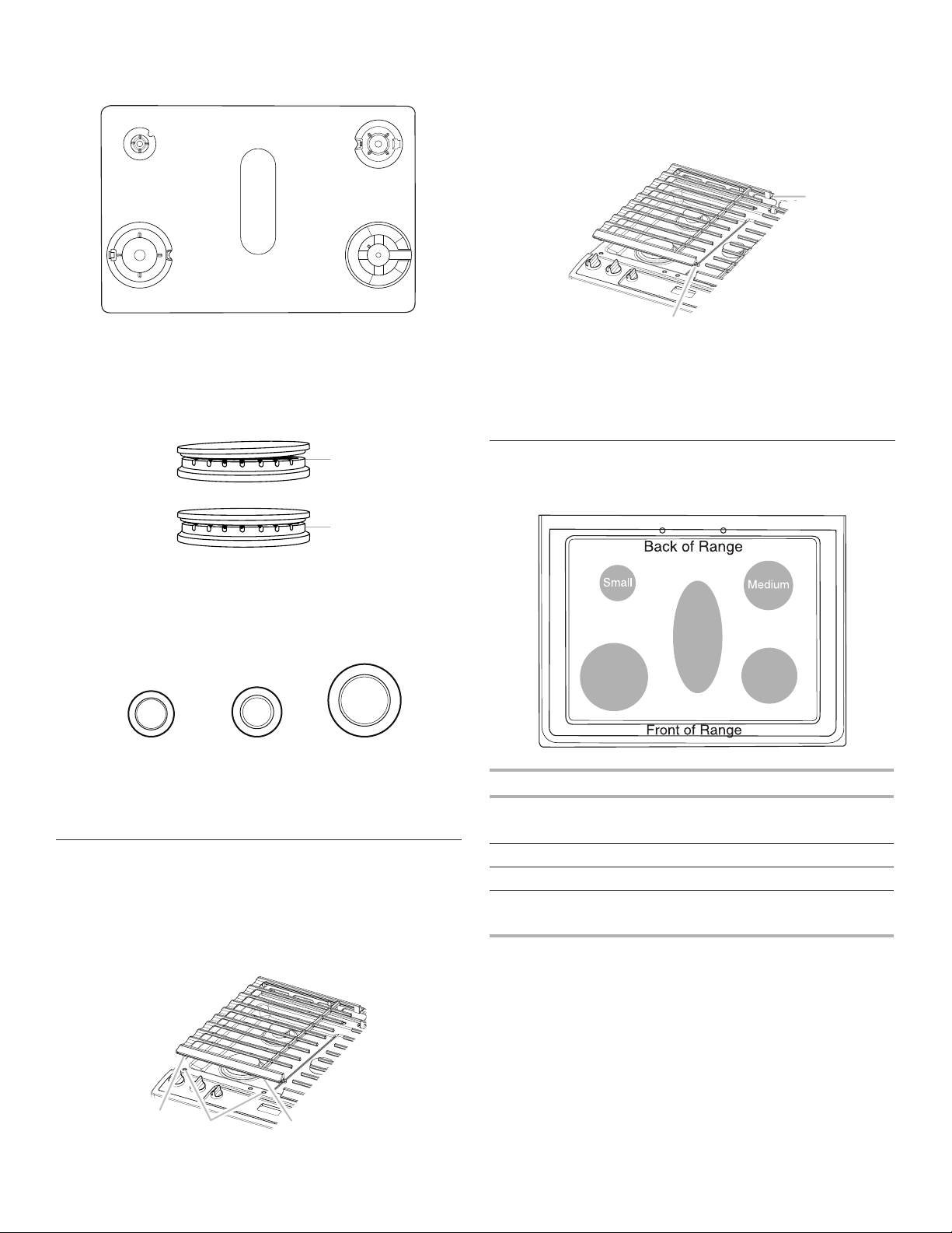
Surface Grates
The grates must be properly positioned before cooking. In the
proper position, the grates should be flush and level. Improper
installation of the grates may result in chipping or scratching of
the cooktop.
To ensure proper positioning, align bumpers on grate bottom with
the indentations in the cooktop.
The surface grates interlock using the hook on one end of the
grate and the indent on the other. To remove the grates, lift the
rear of the left grate off the hook, and then lift the front of the right
grate off the hook and pull apart. To replace the grates, replace
the left grate first. Place the front indent of the right grate over the
hook of the left grate, and then lift the rear of the left grate and
place the indent over the hook on the right grate.
Although the burner grates are durable, they will gradually lose
their shine and/or discolor due to the high temperatures of the
gas flame.
Burner Size
Select a burner that best fits your cookware. See the following
illustration and chart.
Burner Size Recommended Use
Small
■ Low-heat cooking
■ Melting chocolate or butter
Medium
■ Multipurpose burner
Wok
■ For large cookware
X-Large
(most powerful)
■ For large cookware
■ Most powerful burner
A
D
EB
A. Small (S)
B. Large (L)
C. Oval D. Medium (M)
E. Large (L)
C
A. Small (AUX)
B. X-Large (UR)
C. Medium D. Medium (SR)
E. Wok
A
B
A. Incorrect
B. Correct
A
A
B
A. Bumpers
B. Alignment indentations
A
B
A. Hook
B. Indent
X-Large
(most
powerful)
Oval
Wok
12
Cookware
IMPORTANT: Do not leave empty cookware on a hot surface
cooking area, element, or surface burner.
Ideal cookware should have a flat bottom, straight sides, and a
well-fitting lid, and the material should be of medium-to-heavy
thickness.
Rough finishes may scratch the cooktop or coils. Aluminum
and copper may be used as a core or base in cookware.
However, when used as a base, they can leave permanent
marks on the surfaces.
Cookware material is a factor in how quickly and evenly heat
is transferred which affects cooking results. A nonstick finish
has the same characteristics as its base material. For example,
aluminum cookware with a nonstick finish will take on the
properties of aluminum.
Cookware with nonstick surfaces should not be used under
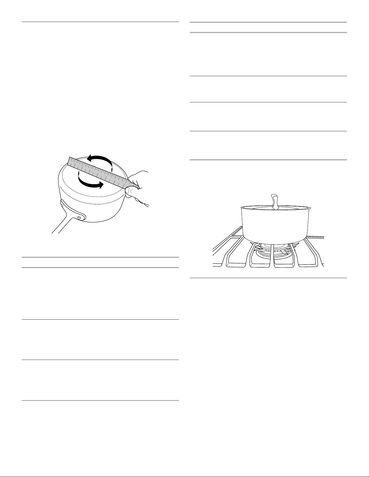
the broiler.
Check for flatness by placing the straight edge of a ruler across
the bottom of the cookware. While you rotate the ruler, no space
or light should be visible between it and the cookware.
Use the following chart as a guide for cookware material
characteristics.
Cookware Characteristics
Aluminum
■ Heats quickly and evenly.
■ Suitable for all types of cooking.
■ Medium or heavy thickness is best
for most cooking tasks.
■ May leave aluminum residues
which may be diminished if cleaned
immediately after cooking.
Cast iron
■ Heats slowly and evenly.
■ Good for browning and frying.
■ Maintains heat for slow cooking.
■ Rough edges or burrs may scratch
the cooktop.
Ceramic or
ceramic glass
■ Follow manufacturer’s instructions.
■ Heats slowly, but unevenly.
■ Ideal results on low-to-medium heat
settings.
■ May scratch the cooktop.
Cookware Characteristics
Copper
■ Heats very quickly and evenly.
■ May leave copper residues which may
be diminished if cleaned immediately
after cooking.
■ Can leave a permanent stain or bond
to the cooktop if overheated.
Earthenware
■ Follow manufacturer’s instructions.
■ Use on low heat settings.
■ May scratch the cooktop.
Porcelain enamel
on steel or cast
iron
■ See stainless steel or cast iron.
■ Porcelain enamel bakeware without the
metal base may bond to the cooktop if
overheated.
Stainless steel
■ Heats quickly, but unevenly.
■ A core or base of aluminum or copper
on stainless steel provides even
heating.
Use flat-bottomed cookware for best cooking results and energy
efficiency. The cookware should be about the same size as
the cooking area outlined on the cooktop or the coil element.
Cookware should not extend more than 1/2" (13 mm) beyond
the surface cooking area or element.
Home Canning
When canning for long periods, alternate the use of surface
burners between batches. This allows time for the most recently
used areas to cool.
■ Center the canner on the grate above the burner.
■ Do not place canner on two surface burners at the same time.
■ For more information, contact your local agricultural
extension office or refer to published home canning guides.
Companies that manufacture home canning products can
also offer assistance.
1
2
3
4
5
6
7
8
9
1 0
1 1
1 2
1 3
1 4
1 5
1 6
1 7
1 8
1 9
2 0
1
2
3
4
5
6
7
13
OVEN
Odors and smoke are normal when the oven is used the first
few times or when it is heavily soiled.
IMPORTANT: The health of some birds is extremely sensitive
to the fumes given off by the oven. Exposure to the fumes may
result in death to certain birds. Always move birds to another
closed and well-ventilated room.
Aluminum Foil
IMPORTANT: To avoid permanent damage to the oven bottom
finish, do not line the oven bottom with any type of foil or liner.
For best cooking results, do not cover entire oven rack with foil
because air must be able to move freely.
Positioning Racks and Bakeware
IMPORTANT: To avoid permanent damage to the porcelain
finish, do not place food or bakeware directly on the oven door
or bottom.
Bakeware
To cook food evenly, hot air must be able to circulate. Allow 2"
(5 cm) of space around bakeware and oven walls. Make sure
that no bakeware piece is directly over another.
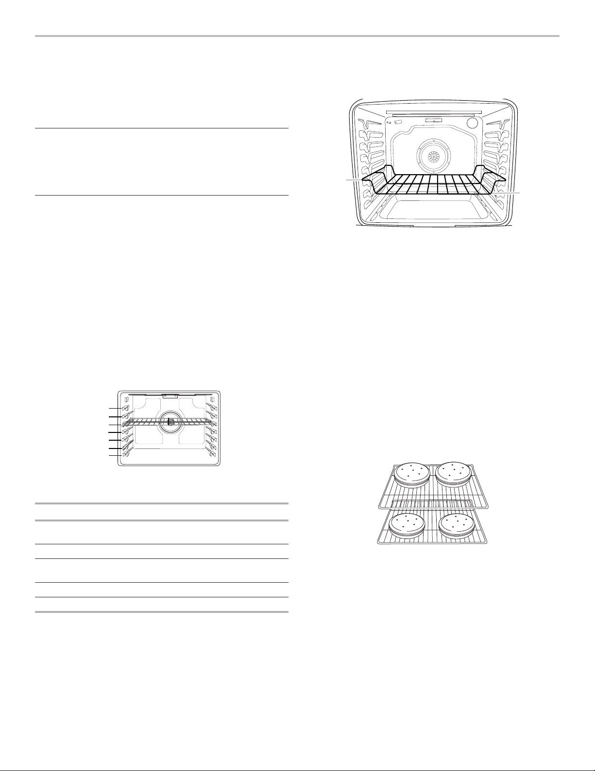
Racks
■ Position racks before turning on the oven.
■ Do not position racks with bakeware on them.
■ Make sure racks are level.
To position a rack, pull it out to the stop position, raise the front
edge, and then lift out. Use the following illustration and charts
as a guide.
The oven has 7 positions for a flat rack, as shown in the previous
illustration and the following table.
Flat Rack Position* Type of Food
7 Broiling/searing meats,
hamburgers, steaks
6 Broiled meats, poultry, fish
3 or 4 Most baked goods, casseroles,
frozen foods
2 Roasted meats
1 Large roasts or poultry
For hamburger patties to have a well-seared exterior and a rare
interior, use a flat rack in rack position 7. Preheat the oven for 5
minutes. Side 1 should cook for approximately 4 to 5 minutes.
Side 2 should cook for approximately 4
1
/
2
to 5
1
/
2
minutes. Expect
a moderate degree of smoke when broiling.
* If your model has a Max Capacity Oven Rack, the recessed
ends must be placed in the rack position above the desired
position of the food. See the following illustration.
IMPORTANT: These rack positions are for flat racks. If a Max
Capacity Oven Rack is used, the rack position must be adjusted
as shown in the previous figure.
Multiple Rack Cooking
Two-rack (non-convection): Use rack positions 2 and 5 or 3
and 6.
Two-rack (convection): Use rack positions 2 and 5 or 3 and 6.
Three-rack (convection): Use rack positions 2 and 7 and a Max
Capacity Oven Rack in rack position 5.
Baking Cookies and Layer Cakes on Two Racks
Baking Layer Cakes
For best results when baking cakes on two racks, use the Bake
function, a flat rack in rack position 5, and a flat rack in rack
position 2. If you do not have 2 flat racks, use a Max Capacity
Oven Rack in rack position 6. Place the cakes on the racks, as
shown. Keep at least 3" (7.6 cm) of space between the front of
the racks and the front cakes.
Baking Cookies
For best results when baking cookies on two racks, use the
Convection Bake function, a flat rack in rack position 5, and a flat
rack in rack position 2.
If you do not have two flat racks, use a flat rack in rack position 2
and a Max Capacity Oven Rack in rack position 6.
If you do not have Convection Bake, use the standard Bake
function.
7
6
5
4
3
2
1
A
B
A. Ends of rack in position 3
B. Food in position 2

14
Oven Vent
The oven vent releases hot air and moisture from the oven
and should not be blocked or covered. Blocking or covering the
oven vent will cause poor air circulation, affecting cooking and
cleaning results. Do not set plastics, paper, or other items that
could melt or burn near the oven vent.
Baking and Roasting
Preheating
When beginning a Bake or Convect Bake cycle, the oven will
begin preheating after Start is pressed. The oven will take
approximately 12 to 15 minutes to reach 350°F (177°C) with all
of the oven racks provided with your oven inside the oven cavity.
Higher temperatures will take longer to preheat. The preheat
cycle rapidly increases the oven temperature. The actual oven
temperature will go above your set temperature to offset the heat
lost when your oven door is opened to insert food. This ensures
that when you place your food in the oven, the oven will begin at
the proper temperature. Insert your food when the preheat tone
sounds. Do not open the door during preheat before the tone
sounds.
Rapid Preheat
Rapid Preheat can be used to shorten the preheating time.
Only one standard flat oven rack should be in the oven during
Rapid Preheat. Extra racks should be removed prior to starting
Rapid Preheat. The preheating cycle should be completed
before placing food in the oven. When the Rapid Preheat cycle
is complete, the oven starts a normal Bake cycle.
IMPORTANT: Rapid Preheat should be used only for one-rack
baking.
Oven Temperature
While in use, the oven elements will cycle on and off as needed
to maintain a consistent temperature, but they may run slightly
hot or cool at any point in time due to this cycling. Opening the
oven door while in use will release the hot air and cool the oven
which could impact the cooking time and performance. It is
recommended to use the oven light to monitor cooking progress.
NOTE: On models with convection, the convection fan may run
in the non-convection Bake mode to improve oven performance.
Temperature Management System
The temperature management system electronically regulates the
oven heat levels during preheat and Bake to maintain a precise
temperature range for optimal cooking results. The bake and broil
elements or burners cycle on and off in intervals. On convection
range models, the fan will run while preheating and may be
cycled on and off for short intervals during bake to provide the
best results. This feature is automatically activated when the oven
is in use.
Before baking and roasting, position racks according to the
“Positioning Racks and Bakeware” section. When roasting, it is
not necessary to wait for the oven preheat cycle to end before
putting food in, unless it is recommended in the recipe.
Frozen Bake™
Frozen Bake™ Technology automatically adjusts the
manufacturer’s bake time by combining preheating and baking,
to deliver great packaged frozen food results without the wait.
There are six programmed food options to choose from: Pizza,
Lasagna, Nuggets, Fries, Pie, and Meal. The Frozen Bake™
cycles have been customized to work only with these foods.
When using Frozen Bake™ Technology, it is important that
you follow all manufacturer’s instructions including venting,
covering, stirring or placing on a baking sheet to ensure a good
result. When cooking frozen meals, only cook items that provide
instructions for cooking in a conventional oven. Place your dish
in the center of the rack and select one of the rack positions
recommended for Frozen Bake in the Positioning Racks and
Bakeware section and bake only one package or pan at a time.
Use the temperature and maximum bake time from the package.
A tone will alert you to check the food for doneness before the
cook time is complete and again at the end of the cook time. The
display will prompt you to add additional cook time if desired or
end the cycle.
Broiling
When broiling, preheat the oven for 5 minutes before putting
food in, unless recommended otherwise in the recipe. Position
food on grid in a broiler pan, and then place it in the center of
the oven rack.
IMPORTANT: Close the door to ensure proper broiling
temperature.
Changing the temperature when broiling allows more precise
control when cooking. The lower the broil setting is, the slower
the cooking. Thicker cuts and unevenly shaped pieces of meat,
fish and poultry may cook better at lower broil settings. Use rack
6 or 7 for broiling. Refer to the “Positioning Racks and Bakeware”
section for more information.
On lower settings, the broil element will cycle on and off to
maintain the proper temperature.
■ For best results, use a broiler pan and grid. It is designed
to drain juices and help avoid spatter and smoke.
If you would like to purchase a broiler pan, one may be
ordered.
A
A. Oven vent
15
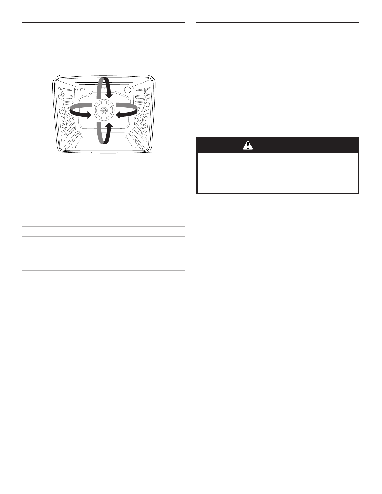
Convection Cooking
In a convection oven, the fan-circulated hot air continually
distributes heat more evenly than the natural movement of air
in a standard thermal oven. This movement of hot air helps
maintain a consistent temperature throughout the oven, cooking
foods more evenly, crisping surfaces while sealing in moisture,
and yielding crustier breads.
During convection baking or roasting, the bake, broil, and
convection elements cycle on and off in intervals while the fan
circulates the hot air. During convection broiling, the broil and
convection elements cycle on and off.
If the oven door is opened during convection cooking, the fan
will turn off immediately. It will come back on when the oven
door is closed.
With convection cooking, most foods can be cooked at a lower
temperature and/or a shorter cooking time than in a standard
thermal oven. Use the following chart as a guide.
Convection Mode Time/Temp. Guidelines
Convection Bake 25°F (15°C) lower temperature;
possible shortened cooking time
Convection Roast Cooking time shortened by up to 30%
Convection Broil Shortened cooking time
Convect Options
Convect Bake - multiple-rack baking or cookies, biscuits, breads,
casseroles, tarts, tortes, cakes
Convect Roast - whole chicken or turkey, vegetables, pork
roasts, beef roasts
Convect Broil - thicker cuts or unevenly shaped pieces of meat,
fish, or poultry
Oven Light
The oven light is a standard 40-watt appliance bulb. Before
replacing, make sure the oven and cooktop are cool and the
control knobs are in the Off position.
To Replace:
1. Unplug range or disconnect power.
2. Turn the glass bulb cover in the back of the oven
counterclockwise to remove.
3. Turn bulb counterclockwise to remove from socket.
4. Replace bulb by turning clockwise.
5. Replace bulb cover by turning clockwise.
6. Plug in range or reconnect power.
Cook Time
To Set a Cook Time:
1. Press the keypad for any cooking function.
2. Press the number keypads to set the desired temperature.
If the temperature entered is not in the range of the
temperatures allowed, the default temperature will be
displayed and audible tones will sound. Enter a temperature
in the allowable range.
3. Press COOK TIME for the selected oven.
4. Press the number keypads to enter the length of time to
cook.
5. Press START. The timer will begin counting down the set time
once the oven has finished preheating.
6. Press the Cancel keypad for the selected oven to clear the
display.
To Set a Cook Time and Stop Time:
NOTE: This function is not available in Convect Bake and
Convect Roast if the Convect Convert Time/Temp feature is used.
1. Press the keypad for any cooking function
2. Press the number keypads to set the desired temperature.
If the temperature entered is not in the range of the
temperatures allowed, the default temperature will be
displayed and audible tones will sound. Enter a temperature
in the allowable range.
3. Press COOK TIME for the selected oven.
4. Press the number keypads to enter the length of time to
cook.
5. Press STOP TIME for the selected oven.
6. Press the number keypads to enter the time of day to stop
cooking.
7. Press START.
The start time is automatically calculated. When the
start time is reached, the oven will automatically turn on.
When the stop time is reached, the oven will shut
off automatically.
8. Press the Cancel keypad for the selected oven to clear the
display.
WARNING
Food Poisoning Hazard
Do not let food sit in oven more than one hour before
or after cooking.
Doing so can result in food poisoning or sickness.
16
RANGE CARE
Clean Cycle
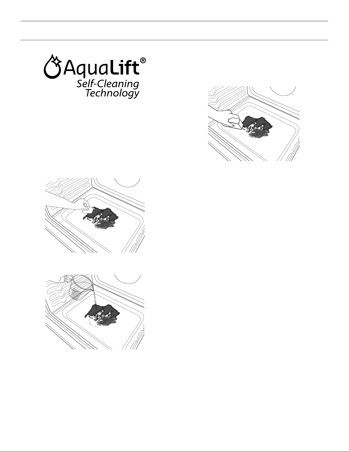
AquaLift
®
Technology is an innovative cleaning solution that
utilizes heat and water to release baked-on spills from the oven
in less than 1 hour. This new cleaning technology is a low-heat,
odor-free alternative to traditional self-cleaning options.
Allow the oven to cool to room temperature before using the
Clean cycle. If your oven cavity is above 200°F (93°C), “Oven
Cooling” will appear in the display, and the Clean cycle will
not be activated until the oven cavity cools down.
To Clean:
1. Remove all racks and accessories from the oven cavity,
and wipe excess soil. Use a plastic scraper to remove
easily removed soils.
2. Pour 1
3
/
4
cups (14 oz [414 mL]) of distilled or filtered water
onto the bottom of the empty oven and close the oven door.
IMPORTANT: Do not use chemicals or other additives with
the water. Do not open the oven door during the Clean cycle.
The water on the oven bottom is hot.
3. Press AQUALIFT SELF CLEAN and then START on the oven
control panel.
4. Allow 40 minutes for cleaning and cooldown. A beep will
sound when the Clean cycle is complete.
5. Press the Cancel keypad at the end of the cycle. Cancel may
be pressed at any time to stop the Clean cycle.
6. Remove the residual water and loosened soils with a sponge
or cloth immediately after the Clean cycle is complete. Much
of the initial 1
3
/
4
cups (14 oz [414 mL]) of water will remain
in the oven after the cycle is completed. If additional soils
remain, leave a small amount of water in the oven bottom
to assist with the cleaning.
7. If any soils remain, remove them with a non-scratch
scrubbing sponge or plastic scraper. Additional Clean
cycles may be run to help remove the stubborn soils.
IMPORTANT: Do not use oven cleaners. The use of chemicals,
including commercial oven cleaners or metal scouring pads,
may cause permanent damage to the porcelain surface of the
oven interior.
NOTES:
■ The range should be level to ensure that the entire surface
of the bottom of the oven cavity is covered by water at the
beginning of the Clean cycle.
■ For best results, use distilled or filtered water. Tap water
may leave mineral deposits on the oven bottom.
■ Before removing the residual water and loosened soils at the
end of the Clean cycle, insert a cloth or paper towel between
the lower edge of the oven door and the front frame to keep
water from spilling onto the front of the range and the floor.
■ Soil baked on through several cooking cycles will be more
difficult to remove with the Clean cycle.
■ Nonabrasive scrub sponges or eraser-style cleaning pads
(without cleaners) can be effective for cleaning the oven
cavity walls, oven door, and oven bottom for difficult soils.
For best results, moisten the pads and sponges before use.
■ Run an additional Clean cycle for stubborn soils.
■ affresh
®
Kitchen Appliance Cleaner and affresh
®
Cooktop
Cleaner may be used to clean the oven bottom, walls, and
door when the oven has finished the cycle and returned to
room temperature. If affresh
®
Cooktop Cleaner is used, it
is recommended to wipe out the cavity with distilled water
as well. Refer to the “Accessories” section for information
on ordering.
■ Additional AquaLift
®
Technology Cleaning Kits may be
obtained by ordering Part Number W10423113RP. See
the “Accessories” section for more information.
■ For assistance with AquaLift
®
Technology, call 1-877-258-0808
in the U.S.A. or 1-800-807-6777 in Canada, or visit our
website at http://whirlpoolcorp.com/aqualift.

17
General Cleaning
IMPORTANT: Before cleaning, make sure all controls are off and
the oven and cooktop are cool. Always follow label instructions
on cleaning products. For additional information, you can visit our
website at www.whirlpool.com.
Soap, water, and a soft cloth or sponge are suggested first unless
otherwise noted.
EXTERIOR PORCELAIN ENAMEL SURFACES
(on some models)
Food spills containing acids, such as vinegar and tomato, should
be cleaned as soon as the entire range is cool. These spills may
affect the finish.
Cleaning Method:
■ Glass cleaner, mild liquid cleaner or nonabrasive
scrubbing pad:
Gently clean around the model/serial/rating plate
because scrubbing may remove numbers.
STAINLESS STEEL (on some models)
NOTE: To avoid damage to stainless steel surfaces, do not use
soap-filled scouring pads, abrasive cleaners, cooktop cleaner,
steel-wool pads, gritty washcloths, or abrasive paper towels.
Damage may occur to stainless steel surfaces, even with one-
time or limited use.
Cleaning Method:
Rub in direction of grain to avoid damaging.
METALLIC PAINT (on some models)
Do not use abrasive cleaners, cleaners with bleach, rust
removers, ammonia, or sodium hydroxide (lye) because the
paint surface may stain.
PORCELAIN-COATED GRATES AND CAPS
Food spills containing acids, such as vinegar and tomato,
should be cleaned as soon as the cooktop, grates, and caps
are cool. These spills may affect the finish.
To avoid chipping, do not bang grates and caps against
each other or hard surfaces such as cast iron cookware.
Do not reassemble caps on burners while wet.
Cleaning Method:
■ Nonabrasive plastic scrubbing pad and mildly
abrasive cleanser:
Clean as soon as cooktop, grates, and caps are cool.
■ Dishwasher (grates only, not caps):
Use the most aggressive cycle. Cooked-on soils should
be soaked or scrubbed before going into a dishwasher.
Although the burner grates are durable, they may lose
their shine and/or discolor when washed in a dishwasher.
SURFACE BURNERS
Food spills containing acids, such as vinegar and tomato,
should be cleaned as soon as the cooktop, grates, and caps
are cool. These spills may affect the finish.
To avoid chipping, do not bang grates and caps against
each other or hard surfaces such as cast iron cookware.
Do not reassemble caps on burners while wet.
Do not clean in the Clean cycle.
Do not clean in dishwasher.
Cleaning Method:
■ Nonabrasive plastic scrubbing pad and mildly abrasive
cleanser:
Clean as soon as cooktop, grates, burners, and caps
are cool.
COOKTOP CONTROLS
To avoid damage to the cooktop controls, do not use steel wool,
abrasive cleansers, or oven cleaner.
To avoid damage, do not soak knobs. When replacing knobs,
make sure knobs are in the Off position.
On some models, do not remove seals under knobs.
Cleaning Method:
■ Soap and water:
Pull knobs straight away from control panel to remove.
CONTROL PANEL AND OVEN DOOR EXTERIOR
To avoid damage to the control panel, do not use abrasive
cleaners, steel-wool pads, gritty washcloths, or abrasive
paper towels.
Cleaning Method:
■ Glass cleaner and soft cloth or sponge:
Apply glass cleaner to soft cloth or sponge, not directly
on panel.
OVEN RACKS
Cleaning Method:
■ Steel-wool pad
■ For racks that have discolored and are harder to slide,
a light coating of vegetable oil applied to the rack guides
will help them slide.
STORAGE DRAWER
Check that storage drawer is cool and empty before cleaning.
Cleaning Method:
■ Mild detergent
OVEN CAVITY
Use AquaLift
®
Technology regularly to clean oven spills.
Do not use oven cleaners.
Food spills should be cleaned when oven cools. At
high temperatures, foods react with porcelain. Staining,
etching, pitting, or faint white spots can result.
Cleaning Method:
■ Clean cycle:
See “Clean Cycle” section.
18
TROUBLESHOOTING
First try the solutions suggested here. If you need further assistance or more recommendations that may help you avoid a service
call, refer to the warranty page in this manual and scan the code there with your mobile device, or visit producthelp.whirlpool.com.
In Canada, visit www.whirlpool.ca.
Contact us by mail with any questions or concerns at the address below:
In the U.S.A.:
Whirlpool Brand Home Appliances
Customer eXperience Center
553 Benson Road
Benton Harbor, MI 49022-2692
In Canada:
Whirlpool Brand Home Appliances
Customer eXperience Centre
200 - 6750 Century Ave.
Mississauga, Ontario L5N 0B7
Please include a daytime phone number in your correspondence.
Electrical Shock Hazard
Plug into a grounded 3 prong outlet.
Do not remove ground prong.
Do not use an adapter.
Do not use an extension cord.
Failure to follow these instructions can result in death,
fire, or electrical shock.
WARNING
Problem Possible Causes and/or Solutions
Nothing will operate
Power supply cord is unplugged: Plug into a grounded 3 prong outlet.
Household fuse is blown or a circuit breaker is tripped: Replace the fuse or reset the circuit breaker.
If the problem continues, call an electrician.
Main or regulator gas shut-off valve is in the Off position: See the Installation Instructions.
The range is improperly connected to the gas supply: Contact a trained repair specialist or see the
Installation Instructions.
Surface burners
will not operate
The control knob is not set correctly: Push in knob before turning to a setting.
Air in the gas lines: If this is the first time the surface burners have been used, turn on any one of the
surface burner knobs to release air from the gas lines.
Clogged burner ports: See the “Sealed Surface Burners” section.
Surface burner
flames are uneven,
yellow and/or noisy
Clogged burner ports: See the “Sealed Surface Burners” section.
Burner caps positioned improperly: See the “Sealed Surface Burners” section.
Range converted improperly: If propane gas is being used, contact a service technician.
Excessive heat
around cookware
on cooktop
Cookware and flame are not matched: The cookware should be centered above the burner with the
bottom sitting level on the grate. The flame should be adjusted so that it does not extend up the sides
of the pan.
Cooktop cooking
results not
what expected
Improper cookware: Ideal cookware should have a flat bottom, straight sides, and a well-fitting lid,
and the material should be of a medium-to-heavy thickness.
Control knob set to incorrect heat level: See the “Cooktop” section.
Range is not level: Level the range. See the Installation Instructions.
Oven will not operate
Air in the gas lines: If this is the first time the oven has been used, turn on any one of the surface burner
knobs to release air from the gas lines.
Control is locked: “Control Lock” will display on the screen. Scroll up to unlock.
The range is in Demo mode: Demo mode will deactivate all oven elements. See “Info” in the “More
Modes” section.
Electronic oven control set incorrectly: See the “Tools” and “More Modes sections.
Oven burner flames
are yellow or noisy
Range converted improperly: If propane gas is being used, contact a service technician.

19
Problem Possible Causes and/or Solutions
Oven temperature
too high or too low
Oven temperature needs adjustment: See “Temperature Calibration” in the “More Modes” section.
Convection fan
not working
The convection cycle is in the first 5 minutes of operation: This is normal. The convection fan
will start running approximately 5 minutes into the cycle.
Oven door is open: If the oven door is opened during convection cooking, the fan will turn off
immediately. It will come back on when the oven door is closed.
Display shows
messages
Power failure (display shows flashing time): Clear the display. On some models, reset the clock,
if needed. See “Preferences” in the “More Modes” section.
Error code (display shows letter followed by number): Depending on your model, press the Cancel
keypad to clear the display. See the “Tools” and “More Modes” sections. If it reappears, call for service.
Range is in Sabbath mode (display shows “Sabbath Mode”): Press the Cancel keypad to exit Sabbath
mode.
Clean cycle did not
work on all spills
Several cooking cycles between Clean cycles or spills on oven walls and doors: Run additional
Clean cycles. See the “Clean Cycle” section for more information.
Mineral deposits
are left on the oven
bottom after the
Clean cycle
Tap water was used in the Clean cycle: Use distilled or filtered water in the Clean cycle.
To remove deposits, use a cloth soaked with vinegar. Then use a cloth dampened with water to thoroughly
remove any vinegar residue.
Range is not level: Mineral deposits will collect on dry areas of the oven bottom during the Clean cycle.
Level the range. See the Installation Instructions.
To remove deposits, use a cloth soaked with vinegar. Then use a cloth dampened with water to thoroughly
remove any vinegar residue.
Oven cooking results
not what expected
Range is not level: Level the range. See the Installation Instructions.
The set temperature was incorrect: Double-check the recipe in a reliable cookbook.
Oven temperature needs adjustment: See “Temperature Calibration” in the “More Modes” section.
Oven was not preheated: See the “Baking and Roasting” section.
Racks were positioned improperly: See the “Positioning Racks and Bakeware” section.
Not enough air circulation around bakeware: See the “Positioning Racks and Bakeware” section.
Darker browning of food caused by dull or dark bakeware: Lower oven temperature 25°F (15°C) or move
rack to a higher position in the oven.
Lighter browning of food caused by shiny or light-colored bakeware: Move rack to a lower position
in the oven.
Batter distributed unevenly in pan: Check that batter is level in the pan.
Incorrect length of cooking time was used: Adjust cooking time.
Oven door was not closed: Be sure that the bakeware does not keep the door from closing.
Oven door was opened during cooking: Oven peeking releases oven heat and can result in longer cooking
times.
Rack is too close to bake burner, making baked items too brown on bottom: Move rack to higher
position in the oven.
Pie crusts browning too quickly: Use aluminum foil to cover the edge of the crust and/or reduce baking
temperature.

20
Noises
Problem Possible Causes and/or Solutions
Surface burner making popping noises
Wet burner: Allow it to dry.
Gas range noises during bake and
broil operations
The following are some normal sounds
with the explanations.
These sounds are normal operational noises that can be heard each time the bake
or broil burners ignite during the cycle.
Pop Gas valve is opening or cycling on and will make a single pop when it snaps open
from the solenoid. It sounds similar to a suction cup being pulled off of a piece of
glass: This is normal.
Click The igniters will click several times until the flame is detected. These are short
clicking sounds like tapping a nail onto a piece of glass: This is normal.
Convection fan relay is cycling on and off (on some models): This is normal.
Woosh or poof
Bake or broil burner is igniting: This is normal.
Oven burner flames are yellow or noisy
Range converted improperly: If propane gas is being used, contact a service technician.
ACCESSORIES
For accessories in the U.S.A., you can visit our website at www.whirlpool.com. In Canada, visit our website at www.whirlpool.ca.
If you have any problems or questions, call Whirlpool Corporation Connected Appliances at 1-866-333-4591.
Complete Cooktop Cleaner Kit
(ceramic glass models)
(includes cleaner, protectant, protectant
applicator, scraper, and cleaner pads)
Order Part Number 31605
affresh
®
Stainless Steel Cleaning
Wipes
(stainless steel models)
Order Part Number W10355049
affresh
®
Cooktop Cleaner
(ceramic glass models)
Order Part Number W10355051
Cooktop Cleaning Pads
(ceramic glass models)
Order Part Number W10391473
affresh
®
Stainless Steel Cleaner
(stainless steel models)
Order Part Number W10355016
affresh
®
Kitchen and Appliance
Cleaner
Order Part Number W10355010
AquaLift
®
Oven Cleaning Kit
Order Part Number W10423113RP
Cooktop Scraper
(ceramic glass models)
Order Part Number WA906B
Granite Cleaner and Polish
Order Part Number W10275756
Canning Unit Kit
(coil models)
Order Part Number 242905
Gourmet Griddle
Order Part Number W10432544
Standard Flat Oven Rack
Order Part Number W10551060
Split Oven Rack
Order Part Number 4396927
Max Capacity Oven Rack
Order Part Number WPW10289145
Porcelain Broiler Pan and Grid
Order Part Number 4396923
Premium Broiler Pan and Roasting
Rack
Order Part Number W10123240
Trim Assembly
5/8" (17 mm) White – Order Part Number
W10675027
5/8" (17 mm) Black – Order Part Number
W10675026
5/8" (17 mm) Stainless Steel – Order Part
Number W10675028
1
1
/
8
" (2.9 cm) White – Order Part Number
W10731885
1
1
/
8
" (2.9 cm) Black – Order Part Number
W10731886
1
1
/
8
" (2.9 cm) Stainless Steel – Order Part
Number W10731887
Backsplash Assembly
White – Order Part Number W10655448
Black – Order Part Number W10655449
Stainless Steel – Order Part Number
W10655450
Grill Kit
Order Part Number W10432545
21
11/14
IF YOU NEED SERVICE:
1. Before contacting us to arrange service, please determine whether your product requires repair. Some
questions can be addressed without service. Please take a few minutes to review the Troubleshooting or
Problem Solver section of the Use and Care Guide, scan the QR code on the right to access additional
resources, or visit www.whirlpool.com/product_help.
2. All warranty service is provided exclusively by our authorized Whirlpool Service Providers. In the U.S. and
Canada, direct all requests for warranty service to:
Whirlpool Customer eXperience Center
In the U.S.A., call 1-800-253-1301. In Canada, call 1-800-807-6777.
If outside the 50 United States or Canada, contact your authorized Whirlpool dealer to determine whether another warranty applies.
WHIRLPOOL
®
MAJOR APPLIANCE
LIMITED WARRANTY
ATTACH YOUR RECEIPT HERE. PROOF OF PURCHASE IS REQUIRED
TO OBTAIN WARRANTY SERVICE.
Please have the following information available when you call the
Customer eXperience Center:
■ Name, address and telephone number
■ Model number and serial number
■ A clear, detailed description of the problem
■ Proof of purchase including dealer or retailer name and address
ONE YEAR LIMITED WARRANTY
WHAT IS COVERED WHAT IS NOT COVERED
For one year from the date of purchase,
when this major appliance is installed,
operated and maintained according to
instructions attached to or furnished
with the product, Whirlpool Corporation
or Whirlpool Canada LP (hereafter
“Whirlpool”) will pay for Factory
Specified Replacement Parts and repair
labor to correct defects in materials or
workmanship that existed when this
major appliance was purchased, or at
its sole discretion replace the product.
In the event of product replacement,
your appliance will be warranted for
the remaining term of the original unit’s
warranty period.
YOUR SOLE AND EXCLUSIVE
REMEDY UNDER THIS LIMITED
WARRANTY SHALL BE PRODUCT
REPAIR AS PROVIDED HEREIN.
Service must be provided by a
Whirlpool designated service company.
This limited warranty is valid only in
the United States or Canada and
applies only when the major appliance
is used in the country in which it was
purchased. This limited warranty is
effective from the date of original
consumer purchase. Proof of original
purchase date is required to obtain
service under this limited warranty.
1. Commercial, non-residential, multiple-family use, or use inconsistent with published user, operator or
installation instructions.
2. In-home instruction on how to use your product.
3. Service to correct improper product maintenance or installation, installation not in accordance with
electrical or plumbing codes or correction of household electrical or plumbing (i.e. house wiring, fuses
or water inlet hoses).
4. Consumable parts (i.e. light bulbs, batteries, air or water filters, preservation solutions, etc.).
5. Defects or damage caused by the use of non-genuine Whirlpool parts or accessories.
6. Conversion of products from natural gas or L.P. gas.
7. Damage from accident, misuse, abuse, fire, floods, acts of God or use with products not approved by
Whirlpool.
8. Repairs to parts or systems to correct product damage or defects caused by unauthorized service,
alteration or modification of the appliance.
9. Cosmetic damage including scratches, dents, chips, and other damage to the appliance finishes
unless such damage results from defects in materials and workmanship and is reported to Whirlpool
within 30 days.
10. Discoloration, rust or oxidation of surfaces resulting from caustic or corrosive environments including
but not limited to high salt concentrations, high moisture or humidity or exposure to chemicals.
11. Food or medicine loss due to product failure.
12. Pick-up or delivery. This product is intended for in-home repair.
13. Travel or transportation expenses for service in remote locations where an authorized Whirlpool
servicer is not available.
14. Removal or reinstallation of inaccessible appliances or built-in fixtures (i.e. trim, decorative panels,
flooring, cabinetry, islands, countertops, drywall, etc.) that interfere with servicing, removal or
replacement of the product.
15. Service or parts for appliances with original model/serial numbers removed, altered or not easily
determined.
The cost of repair or replacement under these excluded circumstances shall be borne by
the customer.
DISCLAIMER OF IMPLIED WARRANTIES
IMPLIED WARRANTIES, INCLUDING ANY IMPLIED WARRANTY OF MERCHANTABILITY OR IMPLIED WARRANTY OF FITNESS FOR A
PARTICULAR PURPOSE, ARE LIMITED TO ONE YEAR OR THE SHORTEST PERIOD ALLOWED BY LAW. Some states and provinces do not allow
limitations on the duration of implied warranties of merchantability or fitness, so this limitation may not apply to you. This warranty gives you specific
legal rights, and you also may have other rights that vary from state to state or province to province.
DISCLAIMER OF REPRESENTATIONS OUTSIDE OF WARRANTY
Whirlpool makes no representations about the quality, durability, or need for service or repair of this major appliance other than the representations
contained in this warranty. If you want a longer or more comprehensive warranty than the limited warranty that comes with this major appliance, you
should ask Whirlpool or your retailer about buying an extended warranty.
LIMITATION OF REMEDIES; EXCLUSION OF INCIDENTAL AND CONSEQUENTIAL DAMAGES
YOUR SOLE AND EXCLUSIVE REMEDY UNDER THIS LIMITED WARRANTY SHALL BE PRODUCT REPAIR AS PROVIDED HEREIN. WHIRLPOOL
SHALL NOT BE LIABLE FOR INCIDENTAL OR CONSEQUENTIAL DAMAGES. Some states and provinces do not allow the exclusion or limitation of
incidental or consequential damages, so these limitations and exclusions may not apply to you. This warranty gives you specific legal rights, and you
also may have other rights that vary from state to state or province to province.
www.whirlpool.com/product_help

22
MERCI d’avoir acheté ce produit de grande qualité. Enregistrez la cuisinière sur www.whirlpool.ca.
Pour référence ultérieure, consignez par écrit les numéros de modèle et de série de votre produit. Vous trouverez les numéros de
modèle et de série sur la plaque signalétique située sur le châssis du four, derrière la partie supérieure droite de la porte du four.
Numéro de modèle_______________________________________ Numéro de série du produit________________________________
Table des matières
INSTRUCTIONS D’UTILISATION
CUISINIÈRE À GAZ
SÉCURITÉ DE LA CUISINIÈRE ..................................................23
La bride antibasculement ...........................................................24
CONSEILS ÉLÉMENTAIRES D’UTILISATION ............................25
Technologie d’autonettoyage AquaLift
®
....................................25
Températures en surface ............................................................25
Préchauffage ..............................................................................25
Brûleurs de surface ....................................................................25
GUIDE DES CARACTÉRISTIQUES .............................................26
Panneau tactile ...........................................................................27
Affichage ...................................................................................27
Affichage du menu .....................................................................27
Méthodes de cuisson .................................................................27
Cuisson assistée ........................................................................29
Favoris ........................................................................................29
Outils ..........................................................................................29
Plus de modes ...........................................................................30
TABLE DE CUISSON ....................................................................31
Brûleurs de surface ....................................................................31
Grilles de surface .......................................................................32
Taille du brûleur ..........................................................................33
Ustensiles de cuisson ................................................................33
Mise en conserve à la maison....................................................34
UTILISATION DU FOUR ...............................................................35
Papier d’aluminium ....................................................................35
Positionnement des grilles et
des ustensiles de cuisson au four .............................................35
Évent du four ..............................................................................36
Cuisson au four et rôtissage ......................................................36
Cuisson au gril ............................................................................37
Cuisson par convection .............................................................37
Lampe du four ............................................................................37
Durée de cuisson .......................................................................37
ENTRETIEN DE LA CUSINIÈRE ..................................................38
Programme de nettoyage ..........................................................38
Nettoyage général ......................................................................39
DÉPANNAGE .................................................................................40
ACCESSOIRES .............................................................................43
GARANTIE ....................................................................................44
23
SÉCURITÉ DE LA CUISINIÈRE
AVERTISSEMENT : Si les renseignements dans ces instructions ne sont pas
exactement observés, un incendie ou une explosion peut survenir, causant des
dommages au produit, des blessures ou un décès.
– Ne pas entreposer ni utiliser de l’essence ou d’autres vapeurs ou liquides inflammables
à proximité de cet appareil ou de tout autre appareil électroménager.
– QUE FAIRE DANS LE CAS D’UNE ODEUR DE GAZ :
•
Ne pas tenter d’allumer un appareil.
•
Ne pas toucher à un commutateur électrique.
•
Ne pas utiliser le téléphone se trouvant sur les lieux.
•
Appeler immédiatement le fournisseur de gaz à partir du téléphone d'un voisin. Suivre
ses instructions.
•
À défaut de joindre votre fournisseur de gaz, appeler les pompiers.
– L’installation et l’entretien doivent être effectués par un installateur qualifié, une agence
de service ou le fournisseur de gaz.
AVERTISSEMENT : L’odorat ne permet pas toujours la détection d’une fuite de gaz.
Les distributeurs de gaz recommandent l’emploi d’un détecteur de gaz (homologation UL ou CSA).
Pour d'autres informations, contacter le fournisseur de gaz local.
En cas de détection d’une fuite de gaz, exécuter les instructions “Que faire dans le cas d’une odeur de gaz”.
Avertissements de la proposition 65 de l'État de Californie :
AVERTISSEMENT : Ce produit contient au moins un produit chimique connu par l’État de Californie pour être à l’origine de
cancers.
AVERTISSEMENT : Ce produit contient au moins un produit chimique connu par l’État de Californie pour être à l’origine de
malformations et autres déficiences de naissance.
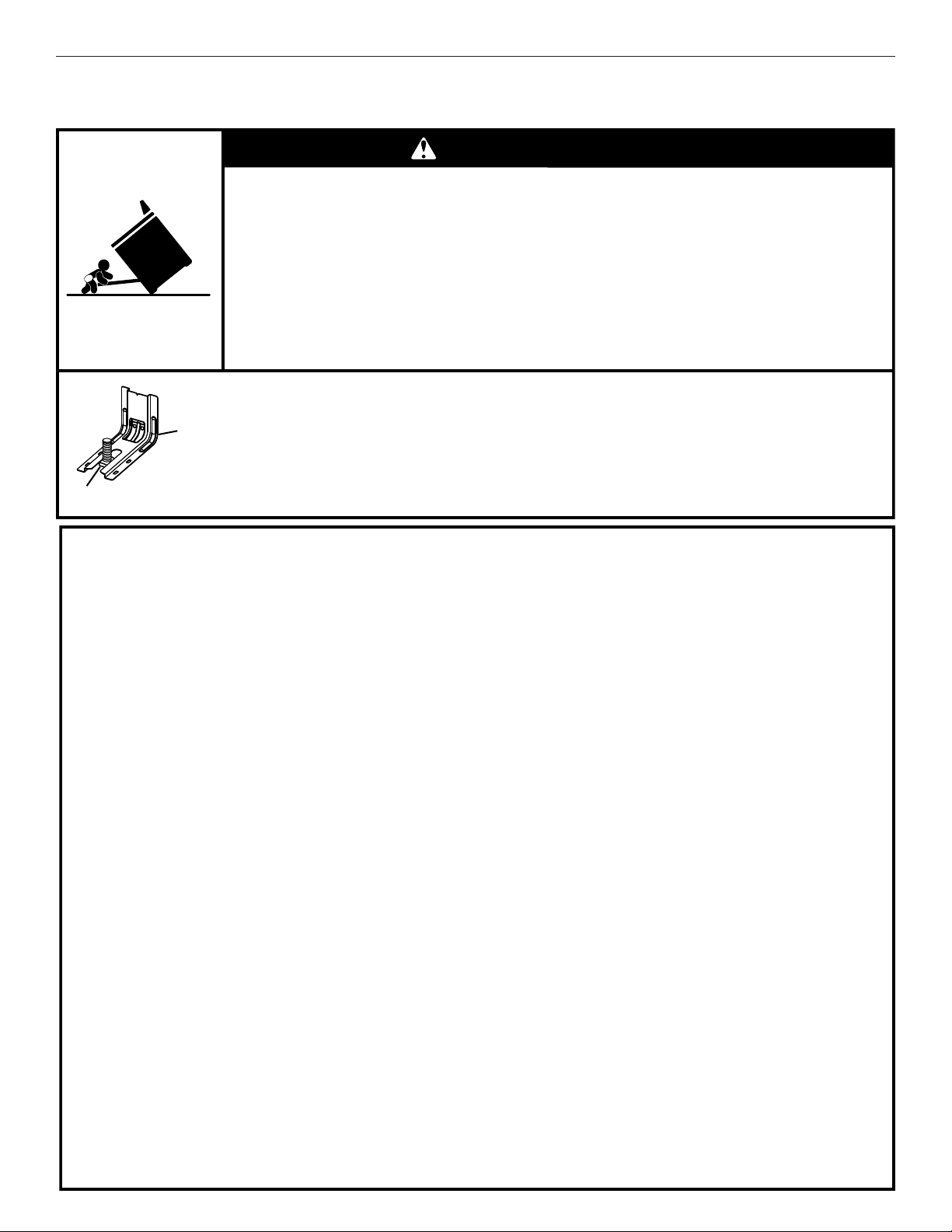
24
La bride antibasculement
Dans des conditions de service normales, la cuisinière ne bascule pas. Elle peut cependant basculer si une force ou un poids excessif
est appliqué sur la porte ouverte alors que la bride antibasculement n’est pas convenablement fixée.
Risque de basculement
Un enfant ou une personne adulte peut faire basculer la cuisinière, ce qui peut causer un
décès.
Vérifier que la bride antibasculement est bien installée et engagée, conformément aux
instructions d'installation.
Réengager la bride antibasculement si la cuisinière a été déplacée.
Ne pas faire fonctionner la cuisinière si la bride antibasculement n'est pas installée et engagée.
Le non-respect de ces instructions peut causer un décès ou des brûlures graves aux enfants et
aux adultes.
Pour vérifier que la bride antibasculement est bien installée et engagée :
• Faire glisser la cuisinière vers l'avant.
• Vérifier que la bride antibasculement est bien fixée au plancher ou au mur.
• Faire de nouveau glisser la cuisinière vers l'arrière de sorte que le pied de la cuisinière
se trouve sous la bride antibasculement.
• Voir les instructions d'installation pour plus de détails.
AVERTISSEMENT
Bride
antibasculement
Pied de la cuisinière
IMPORTANTES INSTRUCTIONS DE SÉCURITÉ
CONSERVEZ CES INSTRUCTIONS
AVERTISSEMENT :
Pour réduire le risque d’incendie, de
choc électrique, de blessures ou de dommages lors de
l’utilisation de la cuisinière, il convient d’observer certaines
précautions élémentaires dont les suivantes :
■ AVERTISSEMENT :
POUR MINIMISER LE RISQUE DE
BASCULEMENT DE LA CUISINIÈRE, ELLE DOIT ÊTRE
BIEN IMMOBILISÉE PAR DES DISPOSITIFS
ANTIBASCULEMENT CORRECTEMENT INSTALLÉS.
POUR VÉRIFIER SI LES DISPOSITIFS SONT
CORRECTEMENT INSTALLÉS, GLISSER LA CUISINIÈRE
VERS L’AVANT ET VÉRIFIER SI LA BRIDE
ANTIBASCULEMENT EST BIEN FIXÉE AU PLANCHER OU
AU MUR, ET GLISSER LA CUISINIÈRE VERS L’ARRIÈRE
POUR QUE LE PIED ARRIÈRE DE LA CUISINIÈRE SOIT
SOUS LA BRIDE ANTIBASCULEMENT.
■
AVERTISSEMENT :
NE JAMAIS utiliser cet appareil
comme dispositif de chauffage de la pièce. Le non-respect
de cette instruction peut entraîner une intoxication au
monoxyde de carbone et une surchauffe du four.
■ AVERTISSEMENT : NE JAMAIS couvrir les fentes,
trous ou passages d'air au fond du four ou couvrir
entièrement une grille avec des matériaux tels que du
papier d'aluminium. Le non-respect de cette instruction
empêche la circulation de l'air dans le four et peut entraîner
une intoxication au monoxyde de carbone. Les feuilles de
papier d'aluminium peuvent également retenir la chaleur et
créer un risque d'incendie.
■ MISE EN GARDE : Ne pas remiser dans des armoires
au-dessus de la cuisinière ou sur le dosseret d’une
cuisinière, des objets que des enfants pourraient vouloir
atteindre. Les enfants pourraient se blesser gravement en
grimpant sur la cuisinière.
■
Installation appropriée – La cuisinière, lorsqu’elle est
correctement installée, doit être reliée à la terre
conformément aux codes électriques locaux ou, en
l’absence de codes locaux, selon le Code électrique national
(US) ANSI/NFPA 70 ou le Code canadien de l'électricité.
S’assurer que la cuisinière est correctement installée et
reliée à la terre par un technicien qualifié.
■ Cette cuisinière est munie d’une fiche de liaison à la terre à
trois broches pour votre protection contre les risques de
choc électrique et doit être branchée directement dans une
prise de courant bien reliée à la terre. Ne pas couper ni
enlever la broche de liaison à la terre de cette fiche.
■ Déconnecter la source de courant électrique avant
l'entretien.
■
Des blessures peuvent survenir du fait d'un mauvais usage
des portes ou des tiroirs de l’appareil tel que se tenir
debout sur la surface, se pencher ou s’asseoir sur les
portes ou tiroirs.
■ Entretien – Garder l’espace autour de la cuisinière dégagé
et libre de matériaux combustibles, d’essence et d’autres
vapeurs et liquides inflammables.
■
Remisage dans ou sur la cuisinière – Des produits
inflammables ne devraient pas être remisés dans un four ou
près des éléments de surface.
■
La taille de la flamme des brûleurs de surface devrait être
ajustée de sorte qu’elle ne dépasse pas le bord de
l’ustensile de cuisson.
Cuisinière autonettoyante –
■ Avant l’autonettoyage du four – Ôter la lèchefrite et son plat
et les autres ustensiles. Essuyer tous les renversements
excessifs avant de mettre en marche le programme
d’autonettoyage.
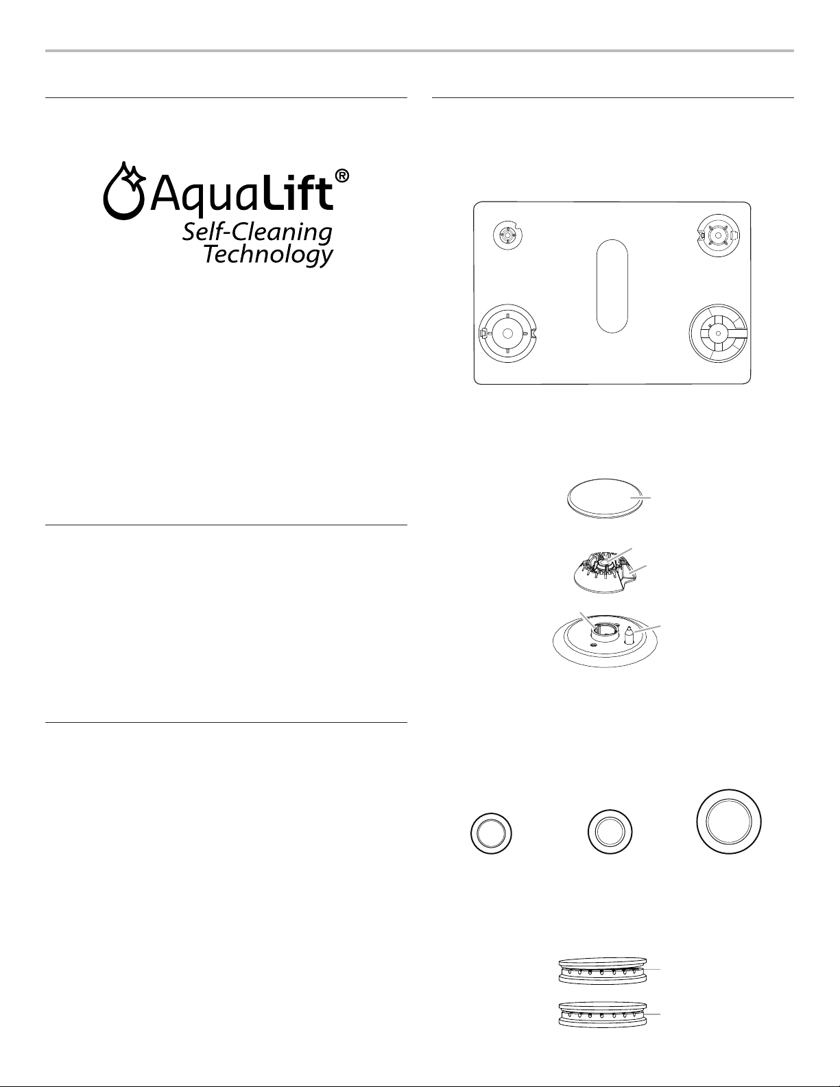
25
CONSEILS ÉLÉMENTAIRES D’UTILISATION
Technologie d’autonettoyage
AquaLift
®
La technologie d’autonettoyage AquaLift
®
est une solution
de nettoyage inédite permettant de réduire la durée, la
température et les odeurs habituellement dégagées par
rapport aux méthodes d’autonettoyage traditionnelles. Avec
la technologie d’autonettoyage AquaLift
®
, une pellicule protectrice
exclusive est activée par la chaleur et l’eau à l’intérieur du four
pour décoller les salissures incrustées. Pour utiliser la technologie
d’autonettoyage AquaLift
®
, il suffit d’essuyer les débris décollés,
de verser de l’eau au fond du four et de lancer le programme
d’autonettoyage AquaLift
®
. Une fois le programme terminé, en
moins de 1 heure à une température plus basse que les méthodes
d’autonettoyage traditionnelles, essuyer simplement l’eau
restante et les salissures décollées. Voir la section “Programme
de nettoyage” pour des instructions plus détaillées. Pour plus
d’informations, des réponses aux questions fréquentes et des
vidéos consacrées à la technologie d’autonettoyage AquaLift
®
,
visiter notre site Web à l’adresse http://whirlpoolcorp.com/
aqualift.
Températures en surface
Lorsque la cuisinière est en marche, toutes ses surfaces peuvent
chauffer, y compris les boutons de commande et la porte du four.
Tiroir-réchaud ou tiroir de remisage
Lorsque le four est en marche, le tiroir peut chauffer. Ne pas
placer d’objets en plastique, en tissu ou susceptibles de fondre ou
de brûler dans le tiroir.
Évent du four
L’évent du four permet l’évacuation de l’air chaud et de l’humidité
du four. Il ne doit pas être obstrué ou couvert. Ne pas placer
près de l’évent du four des objets en plastique, en papier ou
susceptibles de fondre ou de brûler.
Préchauffage
Au début d’un programme de cuisson au four, de cuisson au
four avec convection ou de rôtissage avec convection, le four
commence par un préchauffage une fois la touche Start (mise
en marche) enfoncée. Le four atteint 350 °F (177 °C) en 12 à
15 minutes environ lorsque toutes les grilles fournies avec le four
sont à l’intérieur. Pour atteindre une température plus élevée,
le préchauffage est plus long. Le programme de préchauffage
augmente rapidement la température du four. La température
réelle du four dépasse alors la température programmée,
pour compenser la chaleur perdue à l’ouverture du four pour
y introduire le plat à cuire. Ainsi, le four entame la cuisson
à la température correcte après y avoir placé le plat. Placer
les aliments au four lorsque le signal sonore de préchauffage
retentit. Ne pas ouvrir la porte du four pendant le préchauffage
tant que le signal sonore n’a pas retenti.
Brûleurs de surface
Les bases et les chapeaux des brûleurs doivent être correctement
positionnés avant la cuisson. Votre cuisinière est équipée de
brûleurs et de chapeaux de 3 tailles. Chaque base de brûleur rond
est marquée d’une lettre indiquant la taille du brûleur. Aligner les
bases des brûleurs comme indiqué sur l’illustration suivante :
Aligner l’ouverture du tube d’arrivée de gaz de la base du brûleur
avec le porte-gicleur situé sur la cuisinière, et aligner également
l’électrode d’allumage avec l’encoche de la base du brûleur.
Chaque chapeau de brûleur rond est marqué d’une lettre
indiquant la taille du brûleur. Placer les chapeaux de brûleurs
sur les bases des brûleurs correctes.
AUX
SR
UR
Petit chapeau (AUX) Chapeau moyen (SR) Grand chapeau (UR)
Un chapeau de brûleur correctement placé doit être horizontal.
Si les chapeaux de brûleurs ne sont pas correctement installés,
les brûleurs de surface ne s’allumeront pas. Le chapeau de
brûleur ne devrait pas se balancer ou tanguer s’il est correctement
aligné.
A
D
EB
A. Small (S)
B. Large (L)
C. Oval D. Medium (M)
E. Large (L)
C
A. Petit (AUX)
B. Grand (UR)
C. Moyen D. Moyen (SR)
E. Grand (UR)
A
B
C
D
E
A. Chapeau de brûleur
B. Ouverture du tube
d’arrivée de gaz
C. Base du brûleur
D. Électrode d’allumage
E. Porte-gicleur
A
B
A. Incorrect
B. Correct
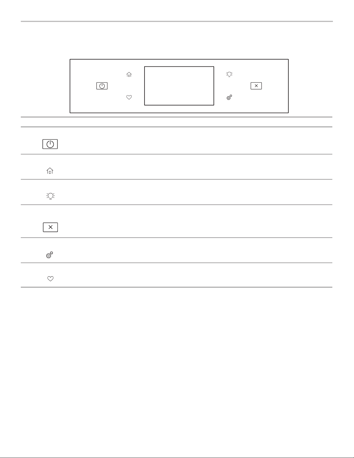
26
GUIDE DES CARACTÉRISTIQUES
Ces instructions concerne plusieurs modèles. Le modèle que vous avez peut comporter toutes les caractéristiques énumérées ou
seulement certaines d’entre elles. Se reporter à ces instructions ou à la section d’aide sur les produits à l’adresse www.whirlpool.ca
pour des instructions plus détaillées.
Clavier Caractéristique Instructions
Alimentation Fonction
d’alimentation
La touche d’alimentation met en marche les fonctions du four et le réveille lorsqu’il est en
mode de veille.
Accueil Écran d’accueil
En appuyant une fois, l’utilisateur peut accéder à l’écran des méthodes de cuisson et de la
cuisson assistée.
Lampe du four Lampe de la
cavité du four
La lampe du four désirée est commandée par une touche située sur le tableau de commande
du four. Alors que la porte du four est fermée, appuyer sur la touche lampe du four pour
allumer ou éteindre la lampe. La lampe du four s’allume à l’ouverture de la porte.
Annulation
du four
Annulation
de la fonction
d’alimentation
La touche annulation du four désactive toutes les fonctions à l’exception de l’horloge, de la
minuterie et du verrouillage des commandes du four.
Outils Fonctions
d’utilisation
du four
Permet de personnaliser les signaux sonores et le fonctionnement du four selon les
préférences de l’utilisateur. Voir la section “Tools” (outils) et “More Modes” (plus de modes).
Favoris Écran des favoris
Le clavier des favoris permet à l’utilisateur de sauvegarder les programmes qu’il utilise le plus
souvent et d’y accéder.
27
Panneau tactile
Le panneau tactile regroupe le menu de commande et les
commandes des différentes fonctions. Le panneau tactile est très
sensible, il suffit d’un léger toucher pour l’activer.
Naviguer vers le haut, le bas, la gauche ou la droite pour explorer
les différentes options et fonctions.
Pour plus d’information sur chaque commande, voir leurs
sections respectives dans ce manuel.
Afchage
L’affichage est pour le menu et les commandes de
fonctionnement du four. L’écran tactile permet de faire défiler les
menus du four. L’affichage est très sensible; il suffit d’un léger
toucher pour l’activer et sélectionner les commandes.
Lorsque le four est utilisé, l’affichage indique l’horloge, le mode,
la température du four, la minuterie de cuisine, et la minuterie du
four si réglée. Si la minuterie du four n’est pas réglée, on peut la
régler à partir de cet écran.
Après environ 2 minutes d’inactivité, l’affichage passe au mode
de veille et s’assombrit. Lorsque le four fonctionne, l’affichage
reste lumineux.
Au cours de l’utilisation, l’affichage indique les menus et les
sélections appropriées pour les options choisies.
Afchage du menu
Si le four est éteint, appuyer sur la touche de marche pour activer
le menu. À partir de l’écran d’accueil, tous les programmes de
cuisson automatique peuvent être activés; tous les programmes
de cuisson manuels peuvent être réglés; les options peuvent être
ajustées et les instructions, les directives de préparation et les
conseils sont accessibles.
Méthodes de cuisson
Le clavier des méthodes de cuisson permet aux utilisateurs de sélectionner l’une des méthodes de cuisson suivantes en fonction de
leur besoin :
■ Cuisson au four
■ Cuisson au gril
■ Cuisson par convection
■ Grillage par convection
■ Rôtissage par convection
■ Maintien au chaud
Utiliser:
1. Appuyer sur la touche de accueil.
2. Appuyer sur la touche de méthodes de cuisson.
3. Sélectionner le mode de cuisson désire.
AVERTISSEMENT
Risque d'empoisonnement alimentaire
Ne pas laisser des aliments dans un four plus d'une
heure avant ou après la cuisson.
Le non-respect de cette instruction peut causer un
empoisonnement alimentaire ou une maladie.
Méthodes de
cuisson
Caractéristique Instructions
BAKE
(cuisson au four)
Cuisson au four
et rôtissage
1. Appuyer sur BAKE (cuisson au four).
2. Sélectionner la température de cuisson souhaitée en naviguant vers la gauche et la droite
ou manuellement à l’aide de la grille située dans le coin supérieur droit pour saisir la
température de cuisson à l’aide du clavier.
3. Appuyer sur mise en marche pour commencer le préchauffage. Lorsque le préchauffage
est terminé, un signal sonore retentit.
4. (Optionnelle) Consulter la section “Rapide” pour obtenir plus d’information sur le
préchauffage rapide du four.
5. Appuyer sur la touche annulation une fois l’opération terminée.
BROIL
(cuisson au gril)
Cuisson au gril
1. Sélectionner BROIL (cuisson au gril).
2. Sélectionner la température de gril souhaitée en naviguant vers la gauche et la droite
ou manuellement à l’aide de la grille située dans le coin supérieur droit pour saisir la
température de cuisson à l’aide du clavier.
3. Appuyer sur START (mise en marche) pour commencer le cussion au gril.
4. Appuyer sur la touche annulation une fois l’opération terminée.

28
Méthodes de
cuisson
Caractéristique Instructions
CONVECT BAKE
(cuisson par
convection)
Convection
baking
1. Sélectionner CONVECT BAKE (cussion par convection).
2. Sélectionner la température de cuisson par convection souhaitée en naviguant vers la
gauche et la droite ou manuellement à l’aide de la grille située dans le coin supérieur droit
pour saisir la température de cuisson à l’aide du clavier.
3. Appuyer sur START (mise en marche) pour commencer le préchauffage. Lorsque le
préchauffage est terminé, un signal sonore retentit.
4. (Optionnelle) Consulter la section “Rapide” pour préchauffer rapidement du four.
5. Appuyer sur la touche annulation une fois l’opération terminée.
Pour plus d’informations, consulter la section “Cuisson par convection”.
CONVECT BROIL
(grillage par
convection)
Convection
broiling
1. Sélectionner CONVECT BROIL (grillage par convection).
2. Sélectionner la température de gril par convection souhaitée en naviguant vers la gauche et
la droite ou manuellement à l’aide de la grille située dans le coin supérieur droit pour saisir
la température de cuisson à l’aide du clavier.
3. Appuyer sur la touche mise en marche.
4. Appuyer sur la touche annulation une fois l’opération terminée.
Pour plus d’informations, consulter la section “Cuisson par convection”.
CONVECT
ROAST
(rôtissage par
convection)
Convection
roasting
1. Sélectionner CONVECT ROAST (rôtissage par convection).
2. Sélectionner la température de rôtissage par convection souhaitée en naviguant vers la
gauche et la droite ou manuellement à l’aide de la grille située dans le coin supérieur droit
pour saisir la température de cuisson à l’aide du clavier.
3. Appuyer sur START (mise en marche).
4. Appuyer sur la touche annulation une fois l’opération terminée.
Pour plus d’informations, consulter la section “Cuisson par convection”.
KEEP WARM
(maintien au
chaud)
Keep warm
(maintien au
chaud)
Les aliments doivent être à la température de service avant d’être placés dans le four chaud.
1. Sélectionner KEEP WARM (maintien au chaud).
2. Sélectionner la température souhaitée en naviguant vers la gauche et la droite ou
manuellement à l’aide de la grille située dans le coin supérieur droit pour saisir la
température de cuisson à l’aide du clavier.
3. Appuyer sur la touche mise en marche.
4. Appuyer sur la touche annulation une fois l’opération terminée.
RAPID (rapide) Préchauffage
rapide du four
Offre la durée de préchauffage le plus rapide pour la fonction Bake (cuisson au four).
Le préchauffage rapide est initialement réglé sur désactivé.
1. Sélectionner RAPID (rapide) pour mettre en marche et arrêter le préchauffage du four.
2. Le réglage en cours s’affiche.
IMPORTANT : Cette caractéristique doit être utilisée pour la cuisson au four sur une seule grille
uniquement. Les grilles inutilisées doivent être retirées avant le préchauffage rapide. On doit
utiliser une grille standard pour la fonction de préchauffage rapide.
Si le préchauffage pour le programme de cuisson au four a déjà commencé, le préchauffage
rapide peut être lancé directement en appuyant sur RAPID PREHEAT (préchauffage rapide).
START TIME
(heure de mise
en marche)
Mise en marche
différée
La mise en marche différée ne doit pas être utilisée pour les aliments tels que pains et gâteaux,
car ils risquent de ne pas bien cuire.
COOK TIME
(durée de
cuisson)
Cuisson
minutée
La cuisson minutée permet d’allumer le four, d’effectuer une cuisson pendant une durée
déterminée et/ou d’éteindre le four automatiquement.

29
Cuisson assistée
Pour réduire le nombre d’étapes de préparation pour la cuisson,
le four possède la technologie Frozen Bake™ qui fait sauter
le préchauffage pour cuir plus rapidement vos plats congelés
préférés. Il est possible de choisir parmi cinq options de
programmes pour aliments : Pizza, lasagne, croquettes/frites,
tartes et repas. Les aliments doivent être immédiatement placés
au four.
Naviguer dans le menu de cuisson assistée jusqu’à atteindre
l’aliment désiré.
Suivre les instructions à l’écran pour personnaliser les réglages
de la cuisson assistée.
Favoris
La fonction des favoris sauvegarde le mode et la température du
four pour vos recettes préférées.
REMARQUE : Un ensemble de favoris et de suggestions peut
être automatiquement affiché à l’écran d’accueil selon l’heure du
repas.
Pour sauvegarder une recette, sélectionner l’icône des favoris et
suivre les étapes à l’écran pour personnaliser les favoris.
Ajouter une image ou un nom au favori pour le personnaliser.
Outils
La touche Tools (outils) permet d’accéder aux fonctions et aux
options pour personnaliser. Ces outils permettent de régler
l’horloge, d’alterner entre unités Fahrenheit et Celsius pour la
température du four, d’activer ou de désactiver les signaux
sonores et les messages, de régler le calibrage du four, de choisir
la langue et plus.
Sélectionner le clavier des outils pour afficher les outils.
Voir la section “Plus de modes” pour plus de renseignements.
Outils Remarque
L’activation à
distance
Appuyer sur Remote Enable (connexion
à distance) pour pouvoir utiliser l’appli
Whirlpool
®
.
REMARQUE : Remote Enable (connexion
à distance) s’arrête aussi lorsque la porte
est ouverte. La fonction doit être réactivée à
chaque utilisation.
Minuterie de
cuisine
Régler la minuterie de cuisine en saisissant
le temps désiré à l’aide du clavier.
1. Sélectionner Kitchen Timer (minuterie de
cuisine).
2. Entrer manuellement le temps désiré.
3. Sélectionner START (mise en marche).
4. Sélectionner Cancel (annulation) pour
mettre fin à la minuterie de cuisine.
Éclairage
Appuyer sur LIGHT (lampe) pour allumer
ou éteindre la lampe. Les lampes du four
s’allument automatiquement à l’ouverture de
la porte.
Autonettoyage
Voir la section “Entretien de la cuisinière”.
Silence
Sélectionner Mute (sourdine) pour enlever ou
remettre les sons du four.
Le verrouillage
des
commandes
Le verrouillage des commandes désactive
le tableau de commande pour éviter
une utilisation involontaire du four. Si le
verrouillage des commandes a été réglé
avant une panne de courant, la fonction
reste activée après cette panne de courant.
Lorsque la commande est verrouillée, seules
les touches Oven Power (réglage de la
minuterie), Tools (outils) et Oven light (lampe
du four) fonctionnent.
Le verrouillage des commandes est préréglé
désactivé, mais peut être activé.
Pour verrouiller/déverrouiller les
commandes :
1. Vérifier que le four est éteint.
2. Sélectionner le clavier “Control Lock”
(verrouillage des commandes).
3. “Control Lock” s’affiche.
4. Naviguer vers le haut pour déverrouiller.
Aucune touche ne fonctionne lorsque les
commandes sont verrouillées.Les fonctions
de la table de cuisson ne sont pas affectées
par le verrouillage des commandes du four..

30
Plus de modes
Mode Sabbat
Pour obtenir de l’aide concernant l’utilisation de ce produit, ainsi
qu’une liste des modèles munis du mode Sabbat, consulter le
www.star-k.org.
Le mode Sabbat permet au four de continuer à fonctionner sur
un réglage de cuisson au four jusqu’à ce qu’on l’éteigne.
Lorsque le mode Sabbat est réglé, seul le programme de cuisson
au four fonctionne. Tous les autres programmes de cuisson et
de nettoyage sont désactivés. Aucun signal sonore ne retentit et
les affichages n’indiquent pas les changements de température.
Lorsque la porte du four est ouverte ou fermée, la lampe du four
ne s’allume ou ne s’éteint pas et les éléments de chauffage ne
s’allument ou ne s’éteignent pas immédiatement.
Si une minuterie de cuisson est réglée, le compte à rebours
n’apparaît pas. La minuterie apparaît fixe au temps réglé.
REMARQUE : Si une panne de courant se produit lorsque le
mode Sabbat est en fonction, le four indiquera que ce mode est
en fonction, mais le programme de cuisson ne fonctionnera pas.
La lumière du four s’allumera si la porte est ouverte pendant cette
période.
Activation du mode Sabbat :
1. Appuyer sur la touche Tools (outils).
2. Appuyer sur More Modes (plus de modes).
3. Sélectionner le mode Sabbat
4. Appuyer de nouveau sur le mode Sabbat pour activer le
mode Sabbat (ce mode est à la base désactivé)
5. Sélectionner “Yes” (oui) pour faire fonctionner le four pendant
le Sabbat.
6. Saisir la température désirée.
(Optionnelle) Pour la cuisson minutée pendant le mode
Sabbat, appuyer sur ADD A COOK TIME (ajouter un temps de
cuisson) du four sélectionné, puis saisir le temps de cuisson
désiré et appuyer sur NEXT (suivant).
7. Sélectionner Start (mise en marche).
Désactivation du mode Sabbat :
Maintenir enfoncée la flèche “vers le haut” pendant 5 secondes.
Réglage de la température
1. Appuyer sur +/- 25 à l’écran pour sélectionner la nouvelle
température.
REMARQUE : Le changement de température n’apparaît pas sur
l’affichage et aucun son n’est émis.
Calibrage de température
IMPORTANT : Ne pas utiliser de thermomètre pour mesurer
la température du four. Les éléments chauffants s’allument
et s’éteignent en alternance pour maintenir une température
constante, mais leur température peut varier légèrement dans un
sens ou dans l’autre du fait de cette alternance.L’ouverture de la
porte du four affecte la mise en marche alternée des éléments et
influence la température.
Le four fournit des températures précises et a été testé avec
soin à l’usine. Toutefois, il peut cuire plus rapidement ou plus
lentement que votre four précédent, et ainsi entraîner des
différences de cuisson ou de brunissage.Si nécessaire, le
calibrage de la température peut se régler en degrés Fahrenheit
ou Celsius.
Un signe moins signifie que le four sera plus froid du nombre
de degrés affiché. L’absence de signe moins signifie que le four
sera plus chaud du nombre de degrés affiché. Utiliser le tableau
suivant comme guide.
REMARQUE : Cet affichage se poursuit pour indiquer la
température du réglage d’origine, il n’indiquera pas le décalage
de calibration.Par exemple, si la température a été réglée à
350 °F (177 °C) et calibrée à -20 °, la température affichée sera
toujours 350 °F (177 °C).
La température du four peut être réglée jusqu’à (+,-) 30° (-18 °C).
Il est recommandé de modifier la température par tranche de 5 °F
(3 °C) jusqu’à l’obtention du résultat souhaité.
Ajustement de la température du four :
1. Appuyer sur la touche Tools (outils).
2. Appuyer sur More Modes (plus de modes).
3. Sélectionner Calibrage de température
4. Naviguer de gauche à droite pour augmenter ou réduire la
température.
Préférences
Heures et dates
Régler les préférences pour l’heure et la date.
■ Vos heures de repas : Régler quand petit déjeuner/déjeuner/
dîner s’affiche.
■ Date
■ Format de l’heure (AM/PM ou 24 hour [heure militaire])
Volume sonore
Régler les préférences pour le volume sonore.
■ Minuteries et alertes
■ Boutons et effets
Réglages de l’écran
Régler la luminosité de l’écran.
■ Luminosité de l’affichage
Régional
Régler les préférences régionales.
■ Langue: Anglais, Français ou Espagnol
■ Unités de température : Fahrenheit et Celsius
WiFi
■ Connexion au réseau : Télécharger l’app Whirlpool de la
boutique d’apps sur votre téléphone mobile. Voir la section
“Configuration de la connectivité” pour des instructions plus
détaillées.
■ Code SAID : Le code SAID s’utilise pour synchroniser un
dispositif intelligent avec votre appareil. Saisir le code SAID
dans l’application Whirlpool
®
.
■ Adresse MAC : L’adresse MAC est affichée pour le module
Wi-Fi.
■ Radio wifi : Met en marche et arrête le Wi-Fi.
Info
■ Service et assistance : Affiche le numéro de modèle, les
informations pour contacter le service à la clientèle et le
diagnostic.
■ Conserver le mode démo : Sélectionner le mode Store
Demo (démonstrateur en magasin) pour mettre en marche et
arrêter ce mode.
■ Restaurer réglages d’usine : Cela restaurera votre produit
aux réglages d’usine par défaut.
■ Modalités et conditions du wifi :
www.whirlpool.com/connect
■ Modalités et conditions du logiciel
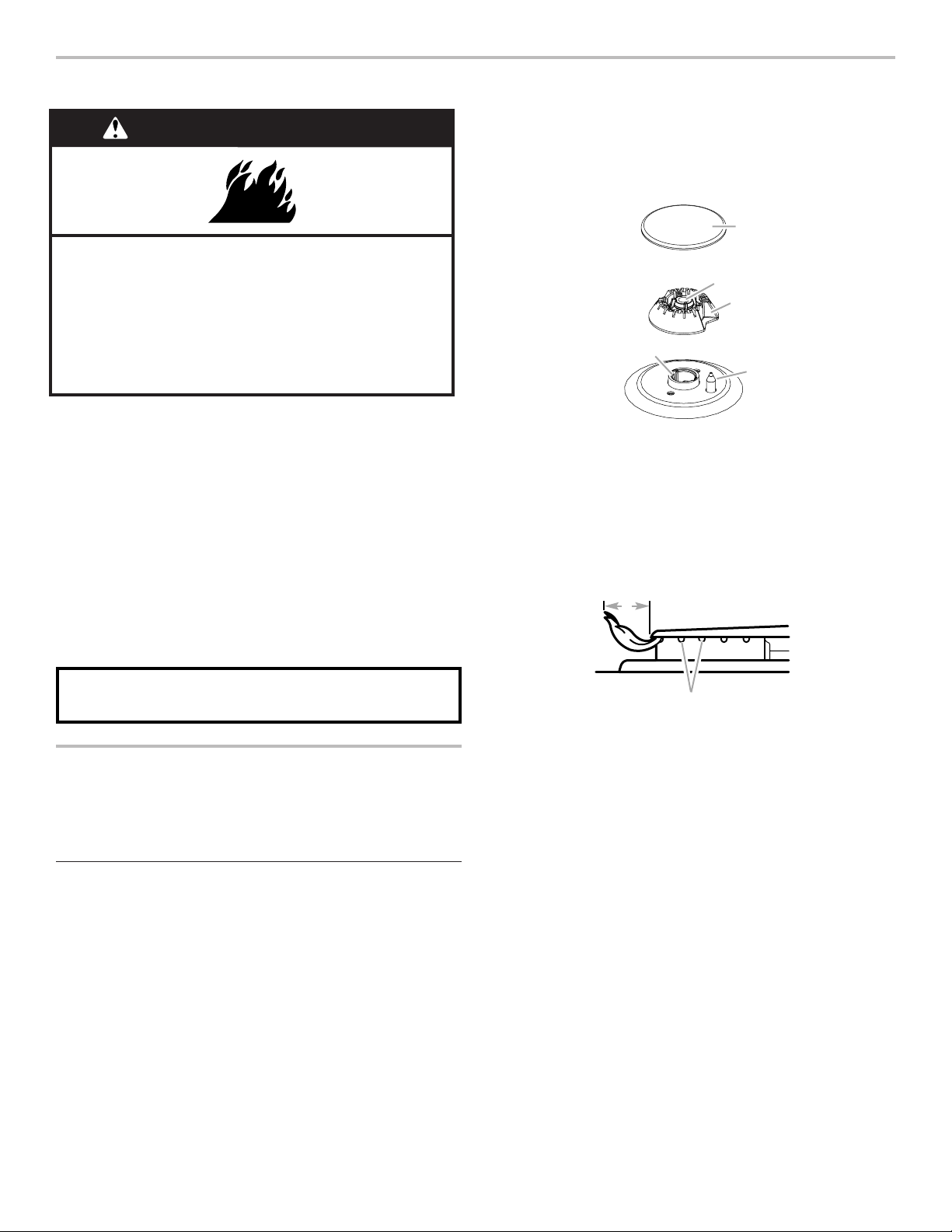
31
TABLE DE CUISSON
Des allumeurs électriques allument automatiquement les brûleurs
de surface lorsque les boutons de commande sont tournés à
Ignite (allumage).
Avant de régler un bouton de commande, placer l’ustensile de
cuisson rempli sur la grille. Ne pas faire fonctionner un brûleur
avec un ustensile de cuisson vide ou sans ustensile de cuisson
sur la grille.
Réglage :
1. Enfoncer et tourner le bouton dans le sens antihoraire à Ignite
(allumage).
Tous les brûleurs de surface émettront un déclic. Seul le
brûleur dont le bouton de commande est placé sur Ignite
produira une flamme.
2. Tourner le bouton à n’importe quel réglage entre High (élevé)
et Low (bas).
Panne de courant
En cas de panne de courant prolongée, les brûleurs de surface
peuvent être allumés manuellement. Tenir une allumette allumée
près d’un brûleur et tourner le bouton dans le sens antihoraire à
IGNITE (allumage). Une fois le brûleur allumé, tourner le bouton
au réglage souhaité.
Brûleurs de surface
IMPORTANT : Ne pas entraver l’évacuation de l’air de
combustion et de ventilation autour des bords des grilles
de brûleur.
Chapeau de brûleur : Toujours garder le chapeau de brûleur
en place lorsqu’un brûleur de surface est utilisé. Un chapeau
de brûleur propre aide à empêcher le mauvais allumage et les
flammes irrégulières. Toujours nettoyer le chapeau du brûleur
après un renversement; enlever et nettoyer régulièrement les
chapeaux tel qu’indiqué à la section “Nettoyage général”.
REMARQUE : Chaque base de brûleur rond est marquée d’une
lettre indiquant la taille du brûleur.
Alignement : Veiller à aligner l’ouverture du tube d’arrivée de
gaz de la base du brûleur avec le porte-gicleur situé sur la table
de cuisson, et à aligner également l’électrode d’allumage avec
l’encoche de la base du brûleur.
REMARQUE : Chaque base de brûleur rond est marquée d’une
lettre indiquant la taille du brûleur.
Ouverture du tube d’arrivée de gaz : Pour que la flamme
s’allume convenablement, il faut que le gaz puisse passer
librement à travers l’orifice. Garder cette zone propre et ne
pas laisser les produits renversés, les aliments, les agents
de nettoyage ou tout autre produit pénétrer dans l’ouverture
du tube d’arrivée de gaz. Toujours utiliser un chapeau de brûleur
pour protéger l’ouverture de gaz contre tout renversement.
Orifices de brûleur : Examiner occasionnellement les flammes
des brûleurs pour en vérifier la taille et la forme tel qu’indiqué
ci-dessus. Une bonne flamme est bleue plutôt que jaune. Garder
cette zone exempte de souillures et ne pas laisser les produits
renversés, les aliments, les agents de nettoyage ou autre produit
pénétrer dans les orifices de brûleur.
Nettoyage :
IMPORTANT : Avant le nettoyage, s’assurer que toutes les
commandes sont désactivées et que la table de cuisson
a refroidi. Ne pas utiliser de nettoyants à four, d’agents de
blanchiment ou de décapants à rouille. Ne pas laver au
lave-vaisselle.
1. Enlever le chapeau et la base du brûleur et nettoyer
tel qu’indiqué à la section “Nettoyage général”.
2. Nettoyer l’ouverture du tube d’arrivée de gaz avec
un chiffon humide.
Risque d’incendie
La flamme d'un brûleur ne devrait pas dépasser le bord
du récipient de cuisson.
Fermer tous les réglages lorsque la cuisson est
terminée.
Le non-respect de ces instructions peut causer un
décès ou un incendie.
AVERTISSEMENT
N’OUBLIEZ PAS : Lors de l’utilisation de la cuisinière, toute
la surface de la table de cuisson peut devenir chaude.
A
B
C
D
E
A. Chapeau de brûleur
B. Ouverture du tube
d’arrivée de gaz
C. Base du brûleur
D. Électrode d’allumage
E. Porte-gicleur
B
A
A. 1" à 1
1
/
2
" (2,5 cm à 3,8 cm)
B. Orifices de brûleur
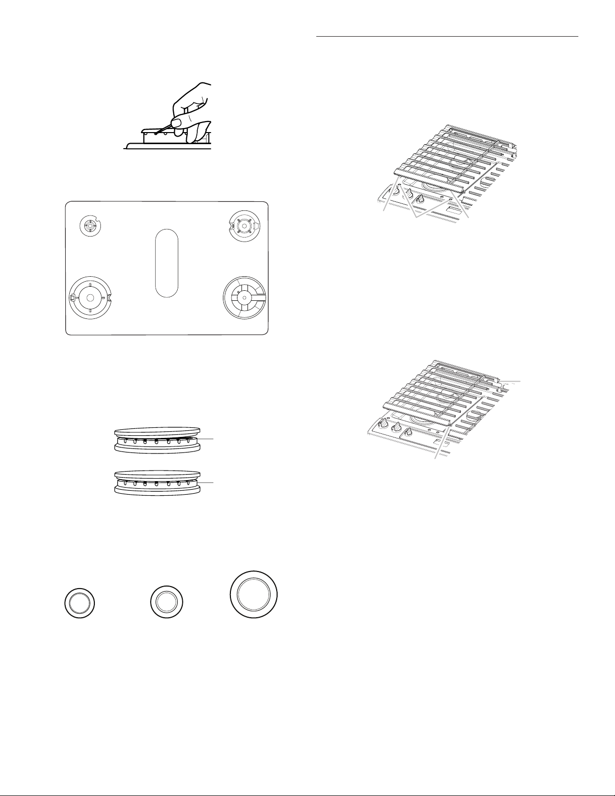
32
3. Nettoyer les orifices de brûleur obstrués avec une épingle
droite tel qu’indiqué. Ne pas agrandir ni déformer l’orifice.
Ne pas utiliser un cure-dents en bois. Si le brûleur a besoin
d’être ajusté, contacter un technicien de réparation qualifié.
4. Réinstaller la base du brûleur. Chaque base de brûleur rond
est marquée d’une lettre indiquant la taille du brûleur. Voir les
illustrations suivantes pour connaître la position des brûleurs.
5. Chaque chapeau de brûleur rond est marqué d’une lettre
indiquant la taille du brûleur. Réinstaller le chapeau du brûleur
et s’assurer qu’il est bien aligné avec la base du brûleur.
Lorsque le chapeau de brûleur est correctement aligné, il ne
se balance pas et n’oscille pas.
IMPORTANT : Les dessous des chapeaux petit et moyen
sont différents. Ne pas placer un chapeau de la taille
incorrecte sur la base du brûleur.
AUX
SR
UR
Petit chapeau (Aux) Chapeau moyen (SR) Grand chapeau (UR)
6. Allumer le brûleur. Si le brûleur ne s’allume pas, vérifier
l’alignement du chapeau. Si le brûleur ne s’allume toujours
pas, éteindre le brûleur. Ne pas réparer le brûleur soi-même.
Contacter un technicien de réparation qualifié.
Grilles de surface
Les grilles doivent être correctement positionnées avant la
cuisson. Les grilles doivent être en affleurement et de niveau
pour être en bonne position. Une mauvaise installation des grilles
peut entraîner l’écaillement ou l’éraflement de la table de cuisson.
Afin de les positionner correctement, aligner les butoirs au-
dessous de la grille avec les indentations sur la table de cuisson.
Les grilles s’imbriquent à l’aide du crochet situé à une extrémité
de l’une d’entre elles et de la fente qui se trouve sur l’autre. Pour
retirer les grilles, soulever l’arrière de la grille de gauche pour la
dégager du crochet, soulever ensuite l’avant de la grille de droite
pour la dégager du crochet, et séparer les grilles. Pour remettre
les grilles en place, remettre la grille de gauche en place en
premier. Placer la fente avant de la grille de droite par-dessus le
crochet de la grille de gauche, soulever ensuite l’arrière de la
grille de gauche et placer la fente par-dessus le crochet de la
grille de droite.
Bien que les grilles de brûleurs soient durables, elles perdront
progressivement de leur lustre et (ou) se décoloreront en raison
des fortes températures produites par les flammes.
A
D
EB
A. Small (S)
B. Large (L)
C. Oval D. Medium (M)
E. Large (L)
C
A. Petit (AUX)
B. Grand (UR)
C. Moyen D. Moyen (SR)
E. Wok
A
B
A. Incorrect
B. Correct
A
A
B
A. Butoirs
B. Indentations d’alignement
A
B
A. Crochet
B. Fente
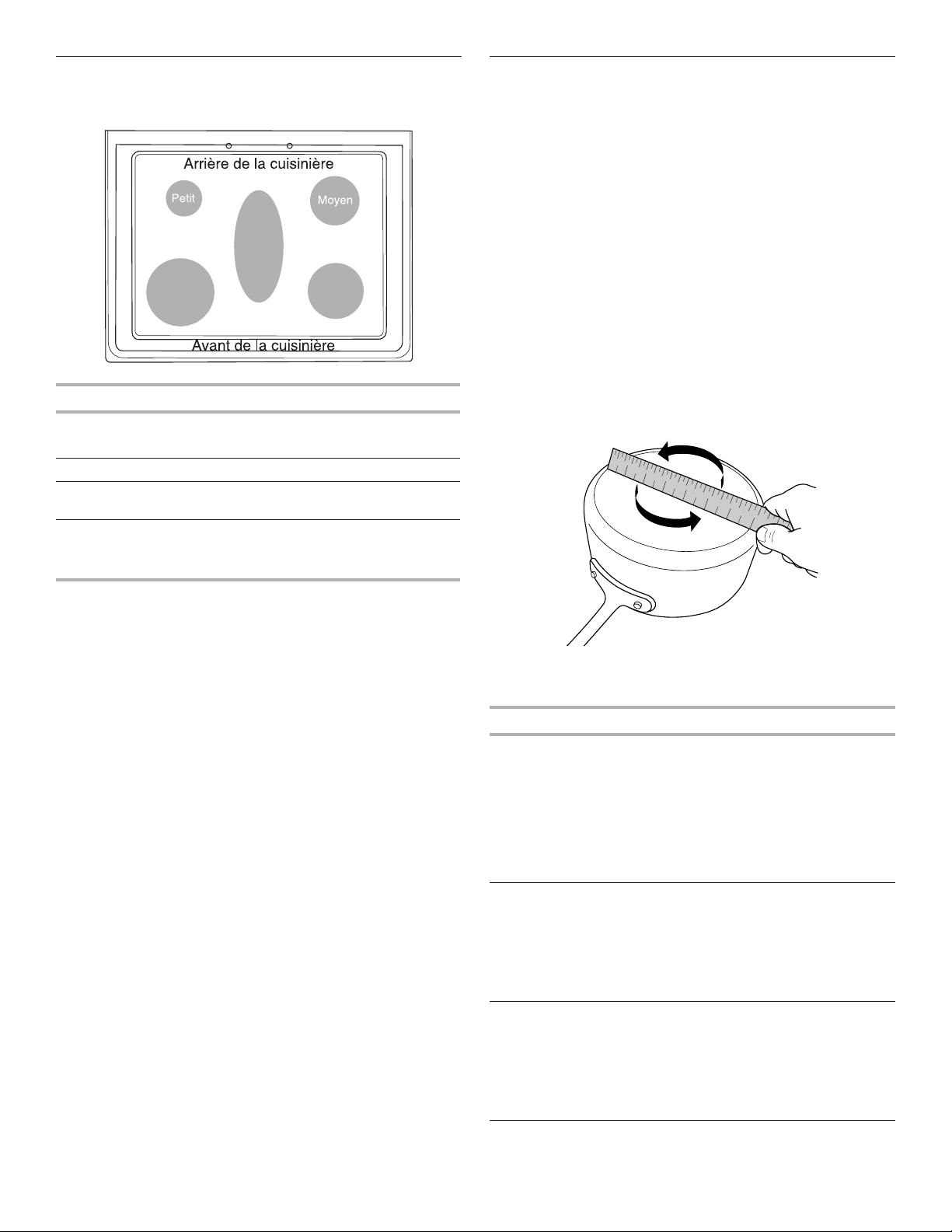
33
Taille du brûleur
Sélectionner un brûleur qui convient le plus aux ustensiles
de cuisson utilisés. Voir le tableau et l’illustration suivants.
Taille du brûleur Utilisation recommandée
Petite taille
■ Cuisson à basse température
■ Faire fondre le chocolat ou le beurre
Taille moyenne
■ Brûleur multifonction
Wok
■ Pour les ustensiles de cuisson
de grande taille
Grande taille
(plus puissant)
■ Pour les ustensiles de cuisson
de grande taille
■ Le brûleur le plus puissant
Ustensiles de cuisson
IMPORTANT : Ne pas laisser d’ustensile de cuisson vide sur une
surface de cuisson, un élément ou un brûleur de surface chauds.
Les ustensiles de cuisson idéals doivent avoir un fond plat, des
parois droites, un couvercle qui ferme hermétiquement et le
matériau doit être d’épaisseur moyenne à forte.
Les finis rugueux peuvent égratigner la table de cuisson.
L’aluminium et le cuivre peuvent être utilisés comme fond ou
base d’un ustensile de cuisson. Toutefois, lorsqu’ils sont utilisés
comme base, ils peuvent laisser des marques permanentes sur
les grilles.
Le matériau d’un ustensile a une influence sur la rapidité
et l’uniformité de la transmission de la chaleur, lesquelles
contribuent aux résultats de cuisson. Un fini antiadhésif a les
mêmes caractéristiques que son matériau de base. Par exemple,
un ustensile de cuisson en aluminium avec un fini antiadhésif
aura les propriétés de l’aluminium.
Les ustensiles de cuisson avec surface antiadhésive ne doivent
pas être utilisés sous le gril.
Vérifier que le récipient est plat en plaçant le bord plat d’une règle
en travers du fond du récipient. Lorsque l’on fait tourner la règle,
aucun espace ni aucune lumière ne devraient être visibles entre
celle-ci et le récipient.
Utiliser le tableau suivant comme guide pour les caractéristiques
du matériau d’ustensile de cuisson.
Ustensile Caractéristiques
Aluminium
■ Chauffe rapidement et uniformément.
■ Convient à tous les genres de cuisson
■ L’épaisseur moyenne ou forte convient
le mieux pour la plupart des tâches
de cuisson.
■ Peut laisser des résidus d’aluminium.
Pour en réduire la quantité, les nettoyer
immédiatement après la cuisson.
Fonte
■ Chauffe lentement et uniformément.
■ Convient pour le brunissage et la friture
■ Maintient la chaleur pour une cuisson
lente.
■ Des rebords anguleux ou mal poncés
peuvent érafler la table de cuisson.
Céramique ou
vitrocéramique
■ Suivre les instructions du fabricant.
■ Chauffe lentement, mais inégalement.
■ Les meilleurs résultats sont obtenus
sur les réglages de chaleur basse
à moyenne
■ Peut érafler la table de cuisson.
Très Grand
(plus
puissant)
Ovale
Wok
1
2
3
4
5
6
7
8
9
1 0
1 1
1 2
1 3
1 4
1 5
1 6
1 7
1 8
1 9
2 0
1
2
3
4
5
6
7
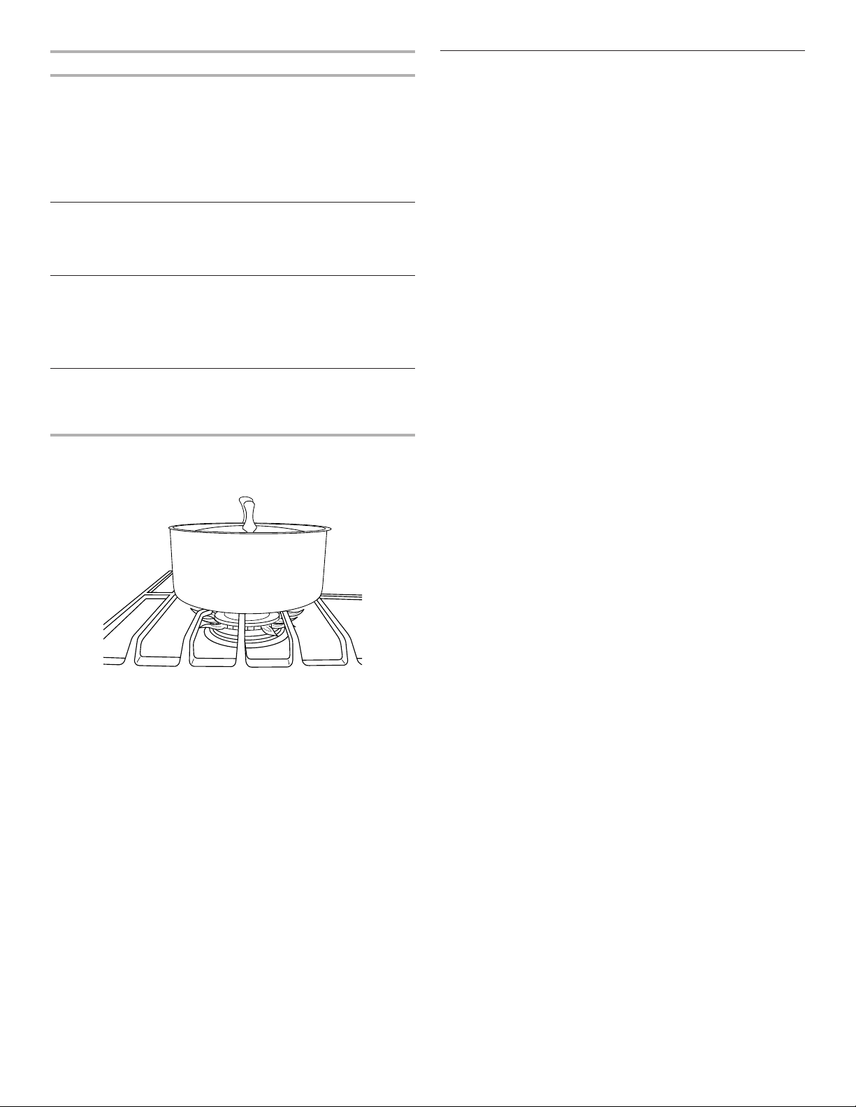
34
Ustensile Caractéristiques
Cuivre
■ Chauffe très rapidement
et uniformément.
■ Peut laisser des résidus de cuivre.
Pour en réduire la quantité, les nettoyer
immédiatement après la cuisson.
■ Peut laisser une tache indélébile ou
adhérer à la table de cuisson en cas
de surchauffe du matériau.
Terre cuite
■ Suivre les instructions du fabricant.
■ Utiliser des réglages de température
basse.
■ Peut érafler la table de cuisson.
Acier émaillé en
porcelaine ou
fonte émaillée
■ Voir acier inoxydable ou fonte.
■ Les ustensiles de cuisson au four
en émail vitrifié dépourvus d’une
base métallique peuvent adhérer à la
table de cuisson en cas de surchauffe
du matériau.
Acier inoxydable
■ Chauffe rapidement, mais inégalement.
■ Un fond ou une base d’aluminium ou
de cuivre sur l’acier inoxydable procure
un chauffage uniforme.
Pour les meilleurs résultats, les ustensiles de cuisson doivent être
centrés au-dessus du brûleur tout en étant posés à l’horizontale
au fond sur la grille. La flamme doit être réglée de sorte qu’elle ne
s’étende pas sur les côtés du plat.
Mise en conserve à la maison
La mise en conserve peut se faire sur une surface de cuisson
lisse en verre ou sur une table de cuisson à éléments tubulaires
traditionnels. Lors de la préparation de conserves pendant de
longues périodes, alterner l’utilisation des surfaces de cuisson
ou des éléments entre les quantités préparées. Ceci permet aux
dernières surfaces utilisées de refroidir.
■ Centrer l’autoclave sur la plus grande surface de cuisson ou
sur le plus grand élément.
■ Ne pas placer l’autoclave sur deux surfaces de cuisson
ou deux éléments à la fois.
■ Pour plus de renseignements, contacter votre bureau de
développement agricole local, ou consulter les guides de
mise en conserve à la maison. Les compagnies qui fabriquent
des produits pour la préparation de conserves peuvent aussi
offrir de l’aide.
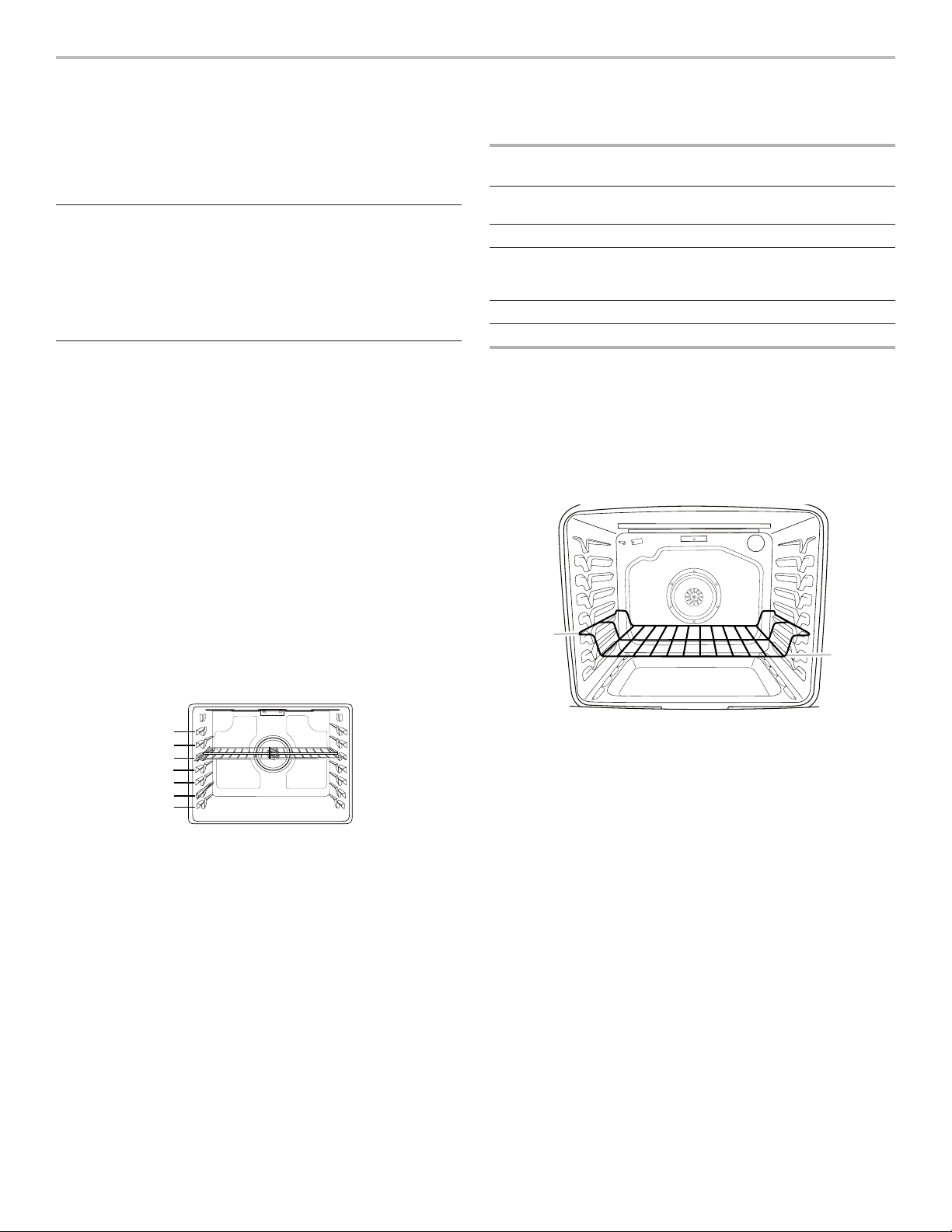
35
UTILISATION DU FOUR
Des odeurs et de la fumée sont normales lorsque le four est
utilisé les premières fois, ou lorsqu’il est très sale.
IMPORTANT : La santé de certains oiseaux est très sensible
aux émanations de fumée. L’exposition aux émanations peut
entraîner la mort de certains oiseaux. Toujours déplacer les
oiseaux dans une autre pièce fermée et bien aérée.
Papier d’aluminium
IMPORTANT : Pour éviter des dommages permanents au fini
du fond du four, ne pas recouvrir le fond du four avec du papier
d’aluminium ou un revêtement quelconque.
Pour assurer une bonne circulation de l’air et des résultats de
cuisson optimaux, ne pas recouvrir la grille entière de papier
d’aluminium.
Positionnement des grilles et des
ustensiles de cuisson au four
IMPORTANT : Afin d’éviter d’endommager irrémédiablement
la finition en émail, ne pas placer d’aliments ou d’ustensiles de
cuisson au four directement sur la porte ou sur le fond du four.
Ustensiles de cuisson
L’air chaud doit pouvoir circuler autour de l’aliment pour le cuire
uniformément. Laisser 2" (5 cm) entre les ustensiles de cuisson
et les parois du four. S’assurer qu’aucun ustensile de cuisson
ne se trouve directement au-dessus d’un autre.
Grilles
■ Placer les grilles avant d’allumer le four.
■ Ne pas déplacer les grilles lorsque des ustensiles de cuisson
se trouvent dessus.
■ S’assurer que les grilles sont horizontales.
Pour déplacer une grille, la tirer jusqu’à la butée, soulever l’avant
puis la retirer. Se servir de l’illustration et du tableau suivants
comme guide.
Le four possède 7 positions pour grille plate, comme indiqué
dans l’illustration précédente et le tableau suivant.
Position de
la grille plate*
Type d’aliment
7 Cuire au gril/griller les viandes,
les hamburgers, les steaks
6 Viandes grillées, volaille, poisson
3 ou 4 La plupart des produits de
boulangerie, plats en sauce,
plats surgelés
2 Viandes rôties
1 Gros rôtis/volailles
Pour qu’une galette à hamburger soit bien saisie à l’extérieur
tout en restant saignante à l’intérieur, utiliser une grille plate en
position 7. Préchauffer le four pendant 5 minutes. Cuire le 1
er
côté pendant 4 à 5 minutes. Cuire le 2
e
côté pendant 4
1
/
2
à 5
1
/
2
minutes. Une légère fumée peut se dégager durant la cuisson au
gril.
* Si votre modèle possède une grille de four à capacité maxi-
male, les bords surélevés doivent être placés dans la position
immédiatement supérieure à la position souhaitée pour les
aliments. Voir l’illustration ci-dessous.
IMPORTANT : Ces positions de grille concernent les grilles
plates. En cas d’utilisation d’une grille de four à capacité
maximale, la position de la grille doit être ajustée en conséquence
comme dans l’illustration précédente.
Cuisson sur plusieurs grilles
Cuisson sur deux grilles (sans convection) : Utiliser les positions
de grille 2 et 5 ou 3 et 6.
Cuisson sur deux grilles (avec convection) : Utiliser les positions
de grille 2 et 5 ou 3 et 6.
Cuisson sur trois grilles (avec convection) : Utiliser les positions
2 et 7 et une grille de four à capacité maximale en position 5.
7
6
5
4
3
2
1
A
B
A. Bordures de grille en position 3
B. Aliments en position 2
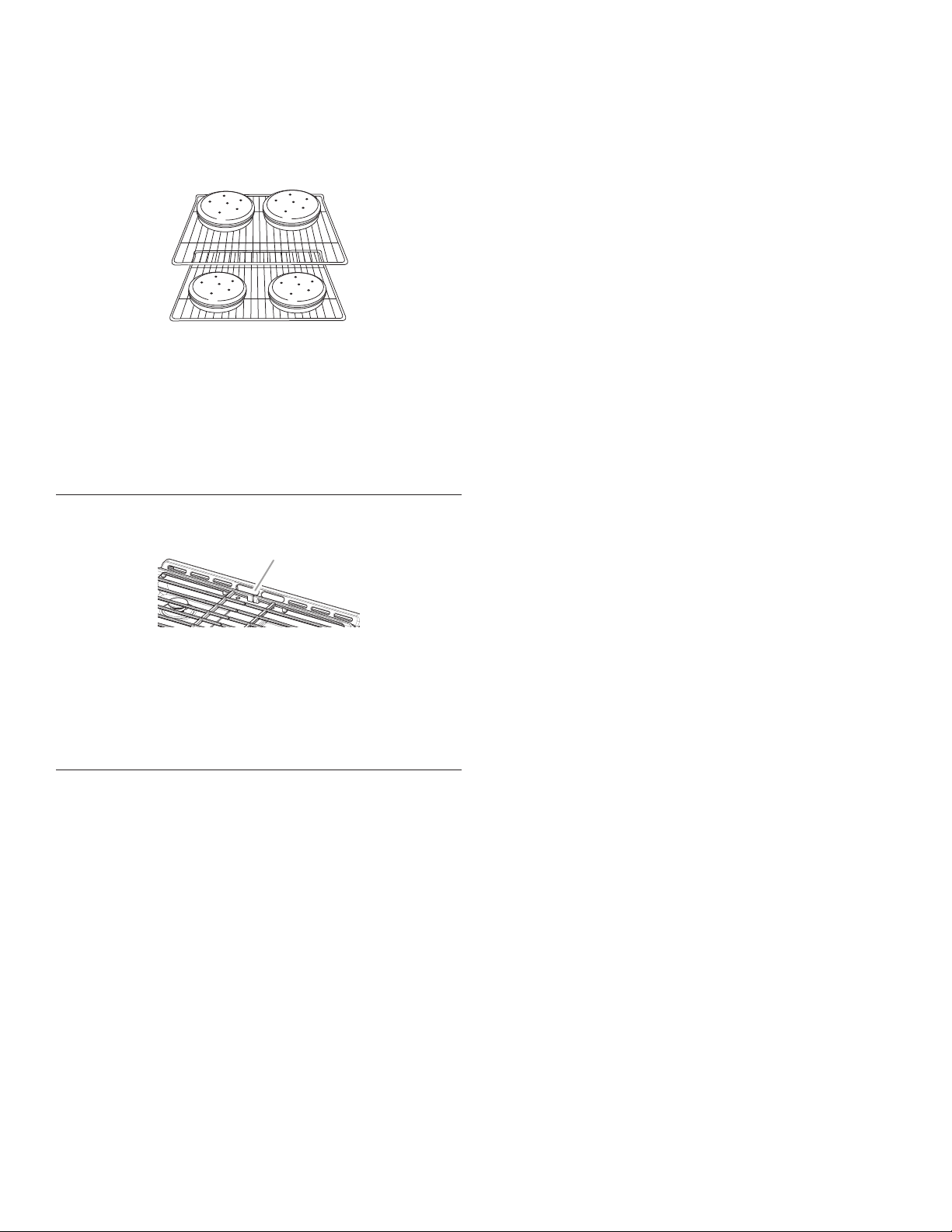
36
Cuisson au four de biscuits et de gâteaux à étages
sur deux grilles
Cuisson au four de gâteaux à étages
Pour des résultats optimaux lors de cuisson au four de gâteaux
sur deux grilles, utiliser les grilles 2 et 5. Pour des résultats
optimaux lors de cuisson au four par convection de gâteaux sur
deux grilles, utiliser les grilles 2 et 5. Placer les gâteaux sur les
grilles tel qu’illustré.
Cuisson au four de biscuits
Pour une cuisson optimale de biscuits sur deux grilles, utiliser la
fonction Convection Bake (cuisson au four par convection), une
grille plate en position 5 et une grille plate en position 2.
Si seule une grille plate est disponible, utiliser une grille plate en
position 2 et une grille de four à capacité maximale en position 6.
Si le four est dépourvu de la fonction Convection Bake (cuisson
au four par convection), utiliser la fonction Bake (cuisson au four)
standard.
Évent du four
L’évent du four permet l’évacuation de l’air chaud et de l’humidité
du four et ne doit pas être obstrué ou couvert. Le fait d’obstruer
ou de couvrir l’évent nuit à la circulation adéquate de l’air et
affecte les résultats de cuisson et de nettoyage. Ne pas placer
près de l’évent du four des produits en plastique, en papier ou
d’autres articles qui pourraient fondre ou brûler.
Cuisson au four et rôtissage
Préchauffage
Au début d’un programme de cuisson au four, de cuisson au
four avec convection, le four commence par un préchauffage
une fois la touche Start (mise en marche) enfoncée. Le four
atteint 350°F (177°C) en 12 à 15 minutes environ lorsque
toutes les grilles fournies avec le four sont à l’intérieur. Pour
atteindre une température plus élevée, le préchauffage est plus
long. Le programme de préchauffage augmente rapidement la
température du four. La température réelle du four dépasse alors
la température programmée, pour compenser la chaleur perdue
à l’ouverture du four pour y introduire le plat à cuire. Ainsi, le four
entame la cuisson à la température correcte après y avoir placé
le plat. Placer les aliments au four lorsque le signal sonore de
préchauffage retentit. Ne pas ouvrir la porte du four pendant le
préchauffage tant que le signal sonore n’a pas retenti.
Préchauffage rapide
La fonction Rapid Preheat (préchauffage rapide) peut servir à
réduire la durée de préchauffage. Durant le préchauffage rapide,
seule une grille doit se trouver dans le four. Les autres grilles
doivent être retirées avant de démarrer le préchauffage rapide. Le
programme de préchauffage doit être terminé avant de placer de
la nourriture dans le four. Une fois le programme de préchauffage
rapide terminé, le four commence un programme normal de
cuisson au four.
IMPORTANT: La fonction de préchauffage rapide doit être
utilisée uniquement pour la cuisson au four sur une seule grille.
Système de gestion de la température
Le système ACCUBAKE
®
régule électroniquement les niveaux
de température du four durant le préchauffage et la cuisson au
four afin de maintenir une gamme précise de températures pour
des résultats de cuisson optimaux. Le brûleur de cuisson au
four s’allume et s’éteint par intermittence. Pour les cuisinières
à convection, le ventilateur peut fonctionner pendant le
préchauffage et peut s’allumer et s’éteindre par intermittence
pendant de courts intervalles afin de fournir de meilleurs
résultats. Cette caractéristique est activée automatiquement
lorsque le four est utilisé.
Le ventilateur de convection ne fonctionne pas durant les 5
premières minutes du programme.
Avant la cuisson au four et le rôtissage, placer les grilles comme
indiqué à la section “Positionnement des grilles et des ustensiles
de cuisson”. Lors du rôtissage, il n’est pas nécessaire d’attendre
la fin du préchauffage du four avant d’y placer la nourriture, sauf
si la recette le recommande.
Technologie Frozen Bake™
La technologie Frozen Bake™ règle automatiquement le temps
de cuisson du fabricant en combinant le préchauffage et la
cuisson pour offrir sans attente de bons résultats avec les
plats congelés. Il est possible de choisir parmi cinq options
de programmes pour aliments : Pizza, lasagne, croquettes,
frites, tartes et repas. Le programme Frozen Bake™ est conçu
pour ne fonctionner qu’avec ces aliments. Lors de l’utilisation
de la technologie Frozen Bake™, il est important de respecter
toutes les instructions du fabricant, incluant la ventilation et le
fait de recouvrir les aliments, de les mélanger ou de les poser
sur une plaque à pâtisserie pour obtenir de bons résultats. Lors
de la préparation de plats congelés, ne cuire que des aliments
munis d’instructions pour un four conventionnel. Placer le plat
au centre de la grille et sélectionner l’une des positions de
grille recommandées pour les plats congelés dans la section
“Positionnement des grilles et ustensiles de cuisson au four”.
Ne faire cuire qu’un plat ou une plaque à la fois. Utiliser la
température et le temps de cuisson maximum indiqué sur
l’emballage.
Une tonalité vous indiquera de vérifier le degré de cuisson avant
la fin du temps de cuisson et à la fin du temps de cuisson.
L’affichage vous demandera d’ajouter du temps de cuisson (au
besoin).
A
A. Évent du four
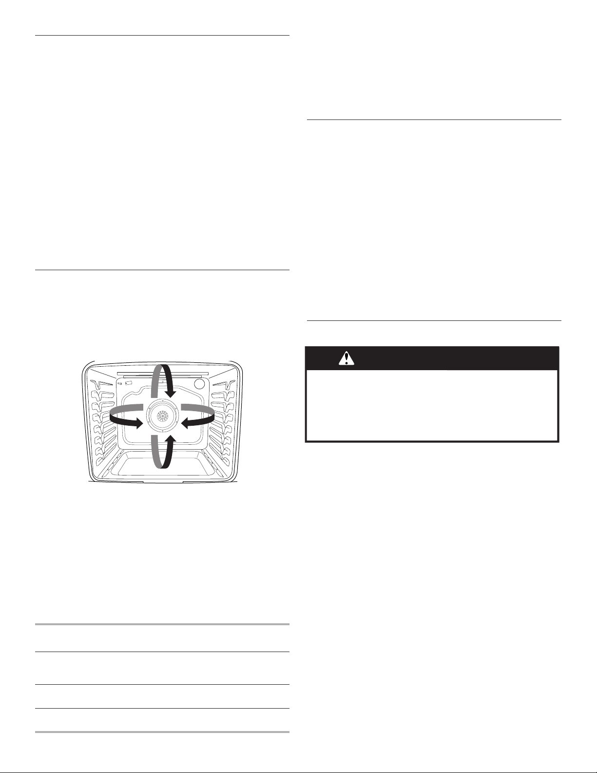
37
Cuisson au gril
Pour la cuisson au gril, préchauffer le four pendant 2 minutes
avant d’y placer des aliments, à moins que la recette ne
recommande autre chose. Placer l’aliment sur la grille de la
lèchefrite, puis placer celle-ci au centre de la grille du four.
IMPORTANT: Fermer la porte pour une température de cuisson
au gril adéquate.
Le changement de température lors de la cuisson au gril permet
un contrôle plus précis de la cuisson. Plus le réglage du gril est
bas, plus la cuisson est lente. Les morceaux épais et de forme
irrégulière de viande, de poisson et de volaille cuisent mieux
à des réglages de gril plus bas. Utiliser la grille 6 ou 7 pour la
cuisson au gril. Consulter la section “Positionnement des grilles
et ustensiles de cuisson” pour plus d’informations.
À des réglages inférieurs, l’élément de cuisson au gril s’allume
et s’éteint par intermittence afin de maintenir une température
adéquate.
■ Pour de meilleurs résultats, utiliser une lèchefrite et une
grille - elles sont conçues pour laisser s’écouler les jus
et aider à éviter les éclaboussures et la fumée.
Il est possible de commander une lèchefrite. Voir la section
“Accessoires”.
Cuisson par convection
Dans un four à convection, l’air chaud que fait circuler le
ventilateur répartit plus uniformément la chaleur que le
mouvement naturel de l’air dans un four thermique standard. Ce
déplacement d’air chaud contribue à maintenir une température
constante dans tout le four, qui permet de cuire les aliments plus
uniformément, de dorer leur surface tout en conservant leur
humidité naturelle et de donner des pains plus croustillants.
Durant la cuisson ou le rôtissage par convection, les éléments
de cuisson au four, cuisson au gril et de convection s’allument et
s’éteignent par intermittence tandis que le ventilateur fait circuler
l’air chaud. Durant la cuisson au gril par convection, les éléments
de cuisson au gril et de convection s’allument et s’éteignent par
intermittence.
Si la porte du four est ouverte durant la cuisson par convection,
le ventilateur s’éteint immédiatement. Il s’allume à nouveau
lorsque la porte du four est fermée.
La cuisson par convection permet de cuire la majorité des
aliments à une température plus basse et/ou moins longtemps
qu’avec un four thermique standard. Utiliser le tableau suivant
comme guide.
Mode de
convection
Recommandation de durée/
temp.
Cuisson au four par
convection
Température plus basse de 25°F
(15°C); réduction éventuelle du
temps de cuisson
Rôtissage par
convection
Temps de cuisson réduit jusqu’à 30 %
Cuisson au gril par
convection
Raccourcissement du temps
de cuisson
Options de cuisson par convection
Cuisson au four par convection : cuisson au four sur plusieurs
grilles de biscuits, pains, plats en sauce, tartes, tourtes
et gâteaux
Rôtissage par convection : poulets ou dindes entiers, légumes,
rôtis de porc, rôtis de boeuf
Cuisson au gril par convection : morceaux plus épais ou inégaux
de viande, de poisson ou de volaille
Lampe du four
La lampe du four est une ampoule standard de 40 watts pour
appareil électroménager. Avant le remplacement, s’assurer que
le four et la table de cuisson sont froids et que les boutons de
commande sont à la position d’arrêt.
Remplacement :
1. Débrancher la cuisinière ou déconnecter la source
de courant électrique.
2. Tourner le protège-ampoule en verre à l’arrière du four
dans le sens antihoraire et l’enlever.
3. Tourner l’ampoule dans le sens antihoraire pour l’enlever
de la douille.
4. Remplacer l’ampoule en la tournant dans le sens horaire.
5. Remplacer le protège-ampoule en le tournant dans
le sens horaire.
6. Brancher la cuisinière ou reconnecter la source de
courant électrique.
Durée de cuisson
Réglage d’une cuisson minutée :
1. Appuyer sur BAKE (cuisson au four) ou appuyer une fois sur
CONVECT (cuisson par convection) pour la cuisson au four
par convection ou deux fois sur CONVECT pour le rôtissage
par convection.
2. Appuyer sur les touches numériques pour entrer une
température autre que celle qui est affichée.
3. Appuyer sur COOK TIME (durée de cuisson). Le témoin
lumineux de la durée de cuisson du four s’allume.
4. Appuyer sur les touches numériques pour entrer la durée
de cuisson.
5. Appuyer sur mise en marche. L’afficheur présente le compte
à rebours de la durée. Lorsque la durée est écoulée, le four
s’éteint automatiquement.
6. Appuyer sur la touche annulation pour effacer l’afficheur.
Réglage d’une cuisson minutée différée :
Avant le réglage, s’assurer que l’horloge est réglée à l’heure
exacte. Voir la caractéristique de touche horloge dans la section
“Guide des caractéristiques”.
1. Appuyer sur BAKE (cuisson au four) ou appuyer une fois sur
CONVECT (cuisson par convection) pour la cuisson au four
par convection ou deux fois sur CONVECT pour le rôtissage
par convection.
2. Appuyer sur les touches numériques pour entrer une
température autre que celle qui est affichée.
3. Appuyer sur COOK TIME (durée de cuisson). Le témoin
lumineux de la durée de cuisson du four s’allume.
AVERTISSEMENT
Risque d'empoisonnement alimentaire
Ne pas laisser des aliments dans un four plus d'une
heure avant ou après la cuisson.
Le non-respect de cette instruction peut causer un
empoisonnement alimentaire ou une maladie.
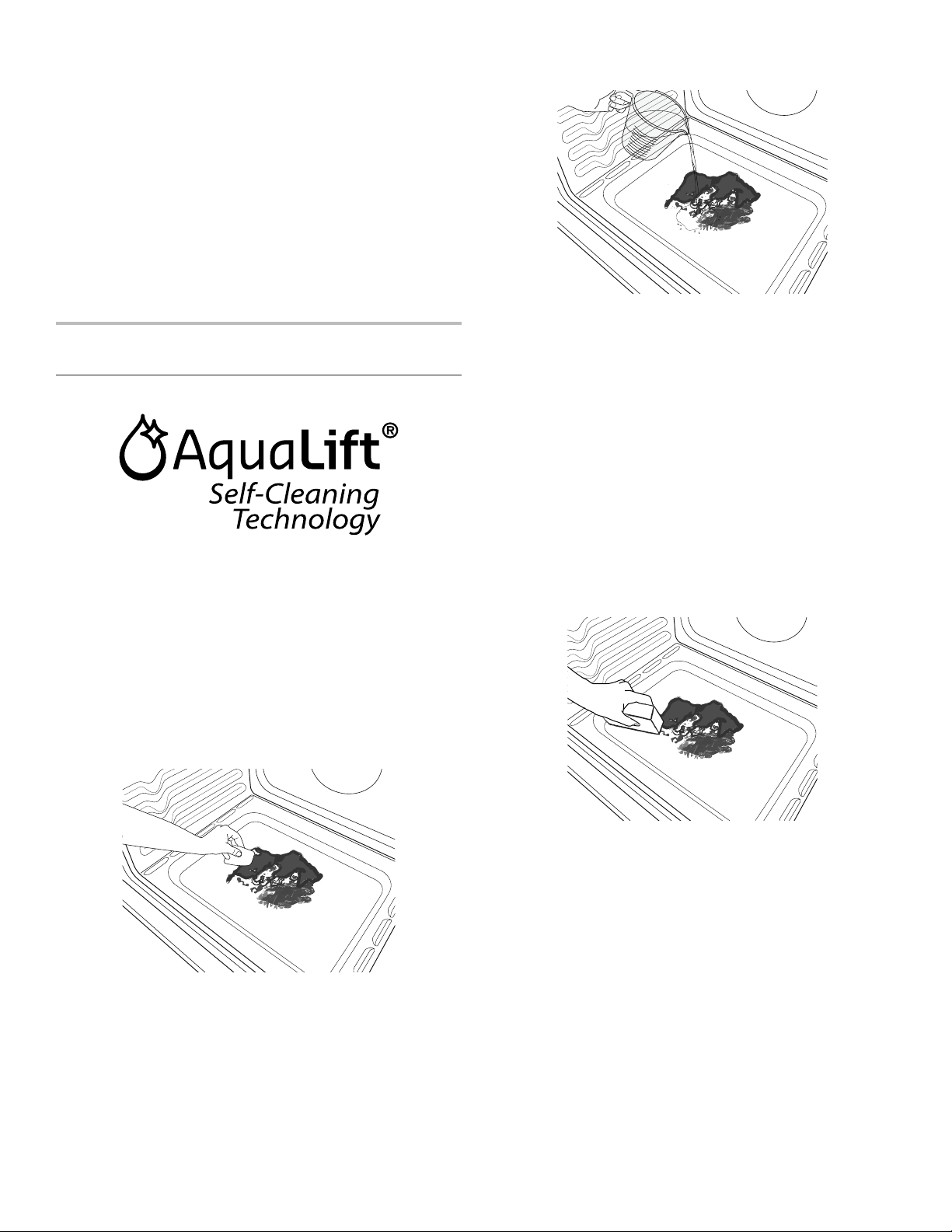
38
4. Appuyer sur les touches numériques pour entrer la durée de
cuisson.
5. Appuyer sur START TIME (heure de mise en marche). Le
témoin lumineux de l’heure de mise en marche/mise en
marche différée du four s’allume.
6. Appuyer sur les touches numériques pour entrer le nombre
d’heures et/ou de minutes dont on souhaite différer l’heure de
mise en marche.
7. Appuyer sur mise en marche.
Lorsque l’heure de mise en marche est atteinte, le four
s’allume automatiquement. Les réglages de température et/
ou de durée peuvent être changés à tout moment après avoir
appuyé sur Start en répétant les étapes 1 à 7. Lorsque la
durée de cuisson prend fin, le four s’éteint automatiquement
et “End” (fin) apparaît sur l’afficheur.
8. Appuyer sur annulation pour effacer l’affichage.
ENTRETIEN DE LA CUSINIÈRE
Programme de nettoyage
La technologie AquaLift
®
est une solution de nettoyage novatrice
qui utilise la chaleur et l’eau pour débarrasser le four des produits
renversés cuits en moins d’une heure. Cette nouvelle technologie
de nettoyage est une alternative à basse température et sans
odeurs aux options traditionnelles de nettoyage automatique.
Laisser le four refroidir et atteindre la température ambiante avant
d’utiliser le programme de nettoyage. Si la température de la
cavité du four est supérieure à 200 °F (93 °C), “Oven Cooling”
(refroidissement du four) apparaît sur l’afficheur et le programme
de nettoyage ne s’activera pas avant que la cavité ait refroidi.
Nettoyage :
1. Retirer toutes les grilles et tous les accessoires de la cavité
du four et essuyer l’excès de saleté. Utiliser une spatule en
plastique pour enlever les saletés faciles à enlever.
2. Verser 1
3
/
4
tasses (14 oz [414 mL]) d’eau distillée ou filtrée
dans le fond du four vide et fermer la porte du four.
IMPORTANT : Ne pas utiliser des produits chimiques ou
d’autres additifs avec l’eau. Ne pas ouvrir la porte du four
au cours du programme de lavage. L’eau au fond du four
est chaude.
3. Appuyer sur CLEAN (autonettoyage) et ensuite sur la touche
mise en marche sur le tableau de commande du four.
4. Accorder 40 minutes pour le nettoyage et le refroidissement.
Un signal sonore vous avertit lorsque le programme de
nettoyage est terminé.
5. Appuyer sur la touche annulation à la fin du programme.
On peut appuyer sur annulation à tout moment pour arrêter le
programme de nettoyage.
6. Enlever l’eau résiduelle et les saletés délogées avec une
éponge ou un chiffon immédiatement après la fin du
programme de nettoyage. La plupart de l’eau initiale
contenue dans 1
3
/
4
tasses (14 oz [414 mL]) restera dans le
four après la fin du programme de nettoyage. S’il reste
encore des saletés, laisser une petite quantité d’eau au fond
du four pour aider le nettoyage.
7. S’il reste des saletés, les enlever avec une éponge à gratter
non abrasive ou une spatule en plastique. Des programmes
de nettoyage supplémentaires peuvent être lancés pour aider
à se débarrasser des saletés tenaces.
IMPORTANT : Ne pas utiliser de nettoyants à four. L’utilisation
de produits chimiques, y compris les nettoyants à four qu’on
retrouve sur le marché, ou des tampons à récurer métalliques,
pourrait causer des dommages permanents à la surface en
porcelaine qui se trouve à l’intérieur du four.
REMARQUES :
■ La cuisinière doit être d’aplomb de façon à s’assurer que la
surface du fond de la cavité du four est couverte par l’eau au
début du programme de nettoyage.
■ Pour des résultats optimaux, utiliser de l’eau distillée ou filtrée.
L’eau du robinet pourrait laisser des dépôts minéraux sur le
fond du four.

39
■ Avant d’enlever l’eau résiduelle et les saletés délogées à la fin
du programme de nettoyage, insérer un chiffon ou un essuie-
tout entre l’extrémité inférieure de la porte du four et l’avant du
châssis, afin d’empêcher l’eau de se déverser sur le devant de
la cuisinière et le plancher.
■ Les saletés cuites suite à plusieurs programmes de cuisson
seront plus difficiles à enlever avec le programme de
nettoyage.
■ Les éponges à gratter non abrasives ou les tampons
nettoyeurs en gomme (sans nettoyants) peuvent être efficaces
pour le nettoyage des parois de la cavité du four, de la porte
du four et du fond du four pour les saletés difficiles. Pour de
meilleurs résultats, mouiller les tampons et les éponges avant
de les utiliser.
■ Exécuter un programme de nettoyage supplémentaire pour
les saletés tenaces.
■ Le nettoyant pour appareils ménagers de cuisine affresh
®
et le nettoyant pour table de cuisson affresh
®
peuvent être
utilisés pour nettoyer le fond du four, ses parois et sa porte
lorsque le four a terminé le programme de nettoyage et que
sa température est redevenue ambiante. Si l’on utilise le
nettoyant pour table de cuisson affresh
®
, il est recommandé
d’essuyer aussi la cavité avec de l’eau distillée. Consulter la
section “Accessoires” pour obtenir des renseignements sur
la commande.
■ Des ensembles de nettoyage à technologie AquaLift
®
supplémentaires peuvent être obtenus en commandant la
pièce numéro W10423113RP. Voir la section “Accessoires”
pour plus d’informations.
■ Pour obtenir de l’aide concernant la technologie AquaLift
®
,
appeler le 1-800-807-6777 ou visiter notre site Web
http://whirlpoolcorp.com/aqualift.
Nettoyage général
IMPORTANT: Avant le nettoyage, s’assurer que toutes les
commandes sont éteintes et que le four et la table de cuisson
sont froids. Toujours suivre les instructions figurant sur les
étiquettes des produits de nettoyage. Pour plus d’informations,
consulter la section service à la clientèle à l’adresse
www.whirlpool.ca.
Du savon, de l’eau et un chiffon doux ou une éponge sont
recommandés, à moins d’indications contraires.
SURFACES EXTÉRIEURES ÉMAILLÉES
(sur certains modèles)
Les éclaboussures alimentaires acides, telles que vinaigre et
tomate, doivent être nettoyées dès que la cuisinière a refroidi.
Ces salissures peuvent endommager le fini.
Méthode de nettoyage :
■ Nettoyant à vitre, nettoyant doux liquide ou tampon à récurer
non abrasif :
Nettoyer doucement autour de la plaque signalétique car
le frottement pourrait en effacer les chiffres.
■ Nettoyant pour cuisine et appareils ménagers affresh
®
référence W10355010 (non fourni) :
Voir la section “Accessoires” pour plus de renseignements.
ACIER INOXYDABLE (sur certains modèles)
REMARQUE : Afin d’éviter d’endommager les surfaces en acier
inoxydable, ne pas utiliser de tampons à récurer savonneux,
de nettoyants abrasifs, de crème à polir pour table de cuisson,
de tampons en laine d’acier, de chiffons de lavage rêches ou
d’essuie-tout abrasifs. Ils peuvent endommager les surfaces en
acier inoxydable, même après usage unique ou limité.
Méthode de nettoyage :
Frotter dans la direction du grain pour éviter les dommages.
■ Nettoyant pour acier inoxydable affresh
®
référence
W10355016 (non fourni) :
Voir la section “Accessoires” pour plus de renseignements.
PEINTURE MÉTALLIQUE (sur certains modèles)
Ne pas utiliser de nettoyants abrasifs, de nettoyants avec agent
de blanchiment, de produits antirouille, d’ammoniaque ou
d’hydroxyde de sodium (soude), car la surface peinte pourrait
se tacher.
GRILLES ET CHAPEAUX ÉMAILLÉS
Les renversements d’aliments contenant des produits acides,
tels que vinaigre et tomates, doivent être nettoyés dès que la
table de cuisson, les grilles et les chapeaux ont refroidi. Ces
salissures peuvent endommager le fini.
Pour éviter l’écaillement, ne pas entrechoquer les grilles et les
chapeaux ni les frapper contre des surfaces dures telles que
les ustensiles en fonte.
Ne pas réinstaller les chapeaux sur les brûleurs lorsqu’ils
sont mouillés.
Méthode de nettoyage :
■ Ustensile de récurage en plastique non abrasif et
nettoyant légèrement abrasif :
Nettoyer dès que la table de cuisson, les grilles et
les chapeaux ont refroidi.
■ Lave-vaisselle (les grilles seulement et non les chapeaux) :
Utiliser le programme le plus intensif. Les saletés cuites
doivent être trempées ou frottées avant d’être placées
au lave-vaisselle.
Bien que les grilles de brûleurs soient durables, elles
perdront progressivement de leur lustre et (ou) se
décoloreront lorsqu’on les lave au lave-vaisselle.
■ Nettoyant pour grille et plateau d’égouttement pour
installation à gaz – Pièce n° 31617 (non fournie) :
Voir la section “Accessoires” pour plus de renseignements.
BRÛLEURS DE SURFACE
Les renversements d’aliments contenant des produits acides,
tels que vinaigre et tomates, doivent être nettoyés dès que la
table de cuisson, les grilles et les chapeaux ont refroidi. Ces
salissures peuvent endommager le fini.
Pour éviter l’écaillement, ne pas entrechoquer les grilles et les
chapeaux ni les frapper contre des surfaces dures telles que
les ustensiles en fonte.
Ne pas réinstaller les chapeaux sur les brûleurs lorsqu’ils
sont mouillés.
Ne pas utiliser le programme d’autonettoyage pour les nettoyer.
Ne pas nettoyer au lave-vaisselle.
Méthode de nettoyage :
■ Ustensile de récurage en plastique non abrasif et nettoyant
légèrement abrasif :
Nettoyer dès que la table de cuisson, les grilles, les brûleurs
et les chapeaux ont refroidi.
■ Nettoyant pour plateau d’égouttement et grille de cuisinière
à gaz (non fourni)
COMMANDES DE LA TABLE DE CUISSON
Afin d’éviter d’endommager les commandes de la table de
cuisson, ne pas utiliser de laine d’acier, de nettoyants abrasifs
ou de nettoyant pour four.
Afin d’éviter toute détérioration, ne pas laisser tremper les
boutons de commande. Lors de la réinstallation des boutons,
s’assurer que chaque bouton est à la position Off (arrêt).
Sur certains modèles, ne pas enlever les joints sous les boutons.
Méthode de nettoyage :
■ Savon et eau :
Tirer les boutons en ligne droite hors du tableau
de commande pour les enlever.
TABLEAU DE COMMANDE ET EXTÉRIEUR
DE LA PORTE DU FOUR
Afin d’éviter d’endommager le tableau de commande, ne pas
utiliser de nettoyants abrasifs, de tampons en laine d’acier, de
chiffons de lavage rêches ou d’essuie-tout abrasifs.
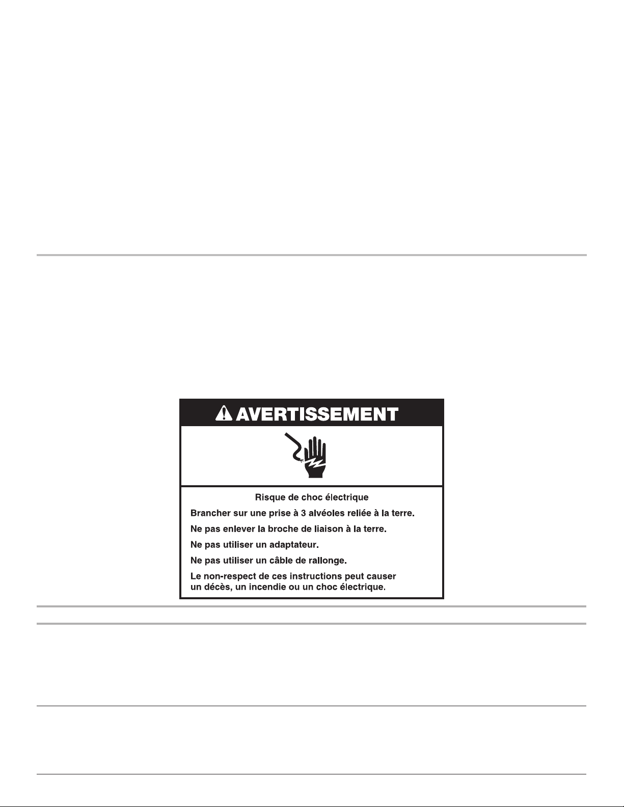
40
Méthode de nettoyage :
■ Nettoyant à vitre et chiffon doux ou éponge :
Appliquer le nettoyant à vitre sur un chiffon doux ou une
éponge, et non directement sur le tableau.
■ Nettoyant pour cuisine et appareils ménagers affresh
®
référence W10355010 (non fourni) :
Voir la section “Accessoires” pour plus de renseignements.
GRILLES DU FOUR
Méthode de nettoyage :
■ Tampon en laine d’acier
■ Pour les grilles ternies qui glissent difficilement, enduire
légèrement les glissières d’huile végétale; cela facilitera leur
glissement.
TIROIR DE REMISAGE
S’assurer que le tiroir est froid et vide avant le nettoyage.
Méthode de nettoyage :
■ Détergent doux
CAVITÉ DU FOUR
Utiliser régulièrement la technologie nettoyage alternatif pour
nettoyer les éclaboussures dans le four.
Ne pas utiliser de nettoyants à four.
Les éclaboussures alimentaires doivent être nettoyées lorsque le
four a refroidi. À haute température, les aliments réagissent avec
l’émail et peuvent provoquer la formation de taches, une attaque
acide, des piqûres ou des décolorations blanchâtres.
Méthode de nettoyage :
■ Programme de nettoyage :
Voir la section “Programme de nettoyage”.
DÉPANNAGE
Essayer d’abord les solutions suggérées ici. Pour obtenir de l’aide ou des conseils qui permettront peut-être d’éviter une intervention
de dépannage, consulter la page de garantie de ce manuel et scanner le code QR avec votre appareil intelligent, ou consultez le site
internet http://www.whirlpool.ca.
Vous pouvez adresser tous commentaires ou questions par courrier à l’adresse ci-dessous :
Au Canada :
Whirlpool Brand Home Appliances
Customer eXperience Centre
200 - 6750 Century Ave.
Mississauga, Ontario L5N 0B7
Dans votre correspondance, veuillez indiquer un numéro de téléphone où l’on peut vous joindre dans la journée.
Problème Causes et/ou solutions possibles
Rien ne fonctionne
Cordon d’alimentation électrique débranché : Le brancher à une prise à 3 alvéoles reliée à la terre.
Un fusible du domicile est grillé ou un disjoncteur s’est ouvert : Remplacer le fusible ou réarmer le
disjoncteur. Si le problème persiste, appeler un électricien.
Le robinet principal d’arrêt ou de réglage du gaz est à la position fermée : Voir les Instructions
d’installation.
La cuisinière n’est pas adéquatement branchée à l’alimentation en gaz : Contacter un technicien de
réparation qualifié ou voir les Instructions d’installation.
Les brûleurs
de surface ne
fonctionnent pas
Le bouton de commande n’est pas correctement engagé : Appuyer sur le bouton avant de le tourner
à un réglage donné.
Présence d’air dans les conduites de gaz : Si c’est la première fois que les brûleurs de surface
sont utilisés, allumer n’importe quel bouton de brûleur de surface afin de libérer l’air présent dans les
canalisations.
Orifices de brûleurs obstrués : Voir la section “Brûleurs de surface scellés”.

41
Problème Causes et/ou solutions possibles
Les flammes
des brûleurs de
surface ne sont pas
uniformes, sont de
teinte jaune et/ou
sont bruyantes
Orifices de brûleurs obstrués : Voir la section “Brûleurs de surface scellés”.
Chapeaux de brûleurs mal positionnés : Voir la section “Brûleurs de surface scellés”.
Conversion inappropriée de la cuisinière : Si l’on utilise du gaz propane, contacter un technicien
de service ou consulter la section “Garantie” pour des renseignements de contact.
Chaleur excessive
autour des ustensiles
de cuisson sur la
table de cuisson
Les ustensiles de cuisson ne correspondent pas à la flamme : Les ustensiles de cuisson doivent être
centrés au-dessus du brûleur tout en étant posés à l’horizontale au fond sur la grille. La flamme doit être
réglée de sorte qu’elle ne s’étende pas sur les côtés du plat.
La cuisson ne produit
pas les résultats
prévus
Ustensiles de cuisson inappropriés : Les ustensiles de cuisson idéals doivent avoir un fond plat, des
parois droites, un couvercle qui ferme hermétiquement et le matériau doit être d’épaisseur moyenne à forte.
Le bouton de commande est réglé sur une puissance de chauffe incorrecte : Voir la section “Utilisation
de la table de cuisson”.
La cuisinière n’est pas d’aplomb : Régler l’aplomb de la cuisinière. Voir les Instructions d’installation.
Le four ne
fonctionne pas
Présence d’air dans les conduites de gaz : Si c’est la première fois que les brûleurs de surface
sont utilisés, allumer n’importe quel bouton de brûleur de surface afin de libérer l’air présent dans les
canalisations.
Les commandes sont verrouillées : Appuyer sur la touche Start (mise en marche) pendant 3 secondes
pour les déverrouiller.
La cuisinière est en mode démonstration : Le mode démonstration désactivera tous les éléments
chauffants. Voir “Information” dans la section “Plus de modes”.
Réglage incorrect des commandes électroniques du four : Voir la section “Outils” et “Plus de modes”.
Les flammes du
brûleur du four sont
jaunes ou bruyantes
Conversion inappropriée de la cuisinière : Si l’on utilise du gaz propane, contacter un technicien
de service ou consulter la section “Garantie” pour des renseignements de contact.
La température du
four est trop élevée
ou trop basse
La température du four doit être ajustée : Voir “Calibrage températur” dans la section “Plus de modes”.
Le ventilateur de
convection ne
fonctionne pas
Le programme de convection se déroule pendant les 5 premières minutes de fonctionnement. Ceci
est normal. Le ventilateur de convection commencera à fonctionner pendant environ 5 minutes dans le
programme.
La porte du four est ouverte : Si la porte du four est ouverte durant la cuisson par convection, le ventilateur
s’éteint immédiatement. Il s’allume à nouveau lorsque la porte du four est fermée.
Des messages
s’affichent
Panne de courant (l’afficheur indique une heure clignotante) : Effacer l’affichage. Sur certains modèles,
régler de nouveau l’horloge au besoin. Voir la “Préférences” à la section “Plus de modes”.
Code d’erreur (l’afficheur indique une lettre suivie d’un numéro) : Selon le modèle, appuyer sur la touche
annulation pour effacer l’affichage. Voir la section “Oulits” et “Plus de modes”. S’il réapparaît, appeler le
service de dépannage. Voir la section “Garantie” pour des renseignements de contact.
La cuisinière est en mode Sabbat (l’afficheur indique “mode Sabbat”) : Appuyer sur la touche annulation
pour quitter le mode Sabbat.
Le programme de
nettoyage n’a pas
éliminé toutes les
salissures
Plusieurs programmes de cuisson entre les programmes de nettoyage, ou éclaboussures sur les
parois et la porte du four : Lancer des programmes de nettoyage supplémentaires. Utiliser le nécessaire
de nettoyage à technologie AquaLift
®
. Pour les salissures tenaces, utiliser le nettoyant pour cuisine et
appareils ménagers affresh
®
ou le nettoyant pour table de cuisson affresh
®
. Voir la section “Accessoires”
et “Programme de nettoyage” pour plus de renseignements.
Des dépôts minéraux
se forment au fond
du four après le
programme de
nettoyage
Le programme de nettoyage a été effectué avec de l’eau du robinet : Utiliser de l’eau distillée ou filtrée
pour le programme de nettoyage.
Utiliser un chiffon imbibé de vinaigre pour enlever les dépôts. Utiliser ensuite un chiffon humide pour enlever
complètement tout résidu de vinaigre.
La cuisinière n’est pas d’aplomb : Les dépôts minéraux s’accumulent sur les surfaces sèches du fond du
four durant le programme de nettoyage. Régler l’aplomb de la cuisinière. Voir les Instructions d’installation.
Utiliser un chiffon imbibé de vinaigre pour enlever les dépôts. Utiliser ensuite un chiffon humide pour enlever
complètement tout résidu de vinaigre.

42
Problème Possible Causes Solutions
Le brûleur de surface émet
des bruits d’éclatemen
Le brûleur est mouillé Le laisser sécher.
Bruits émis par la cuisinière
à gaz lors des opérations
de cuisson au four et de
cuisson au gril
Voici quelques bruits normaux
avec des explications.
Ces bruits sont des bruits de fonctionnement normaux qui peuvent
survenir chaque fois que les brûleurs de cuisson au four ou de
cuisson au gril s’allument au cours du programme.
Éclatement
Le robinet de gaz s’ouvre ou se met en marche; un seul bruit
d’éclatement retentira lorsqu’il se libère du solénoïde. Le bruit est
similaire au bruit de succion qu’émettrait une ventouse que l’on
retire d’une surface de verre.
Ceci est normal.
Cliquez
Les allumeurs émettent plusieurs déclics jusqu’à ce que la flamme
soit détectée. Il s’agit de bruits de claquements courts, similaires au
bruit d’un ongle tapotant sur une surface de verre.
Ceci est normal.
Le relais du ventilateur de convection fonctionne par intermittence
(sur certains modèles)
Ceci est normal.
Crissement ou pouf
Le brûleur de cuisson au four ou au gril est en train de s’allumer. Ceci est normal.
Les flammes du brûleur
du four sont jaunes ou
bruyantes
Conversion inappropriée de la cuisinière. Si du gaz propane est utilisé,
communiquer avec un
technicien.
Bruits
Problème Causes et/ou solutions possibles
La cuisson au four
ne produit pas les
résultats prévus
La cuisinière n’est pas d’aplomb : Régler l’aplomb de la cuisinière. Voir les instructions d’installation.
Le réglage de la température était incorrect : Revérifier la recette dans un livre de cuisine fiable.
La température du four doit être ajustée : Voir “Calibrage température” dans la section “Plus de modes”.
Le four n’a pas été préchauffé : Voir la section “Cuisson au four et rôtissage”.
Les grilles n’étaient pas placées correctement : Voir la section “Positionnement des grilles et ustensiles
de cuisson au four”.
Circulation d’air déficiente autour des ustensiles de cuisson : Voir la section “Positionnement des grilles
et ustensiles de cuisson au four”.
Brunissement excessif des aliments causé par un plat à four terne ou foncé : Diminuer la température
du four de 25°F (15°C) ou placer la grille plus haut dans le four.
Brunissement insuffisant des aliments causé par un plat à four brillant ou clair : Placer la grille plus bas
dans le four.
Répartition irrégulière de la pâte dans le plat : Vérifier que la pâte est répartie uniformément dans le plat.
Durée de cuisson incorrecte : Revoir la durée de cuisson.
Porte du four non fermée : Vérifier que le plat à four n’empêche pas la fermeture de la porte.
La porte du four a été ouverte durant la cuisson : L’ouverture de la porte pour vérifier la cuisson laisse
échapper la chaleur du four et peut allonger la durée de cuisson.
La grille est trop proche du brûleur de cuisson au four, ce qui brunit trop le fond des aliments cuits
au four : Placer la grille plus haut dans le four.
Les croûtes des tartes brunissent trop vite : Recouvrir de papier d’aluminium le périmètre de la croûte
et/ou réduire la température de cuisson du four.

43
ACCESSOIRES
Pour les accessoires, consulter notre site Web www.whirlpool.ca. Si vous avez des problèmes ou des questions,
appelez Whirlpool Corporation Connected Appliances au 1-866-333-4591.
Ensemble d’entretien complet
de la table de cuisson
(modèles avec vitrocéramique)
(comprend le nettoyant, le protecteur, son
applicateur, le grattoir et les tampons à
nettoyer)
Commander la pièce numéro 31605
Protecteur de table de cuisson
(modèles avec vitrocéramique)
Commander la pièce numéro 31463A
Chiffons pour acier inoxydable
affresh
®
(modèles en acier inoxydable)
Commander la pièce numéro W10355049
Nettoyant pour table de cuisson
affresh
®
(modèles avec vitrocéramique)
Commander la pièce numéro W10355051
Tampons à nettoyer les tables
de cuisson
(modèles avec vitrocéramique)
Commander la pièce numéro W10391473
Nettoyant pour acier inoxydable
affresh
®
(modèles en acier inoxydable)
Commander la pièce numéro W10355016
Nettoyant pour cuisine et appareils
électroménagers affresh
®
Commander la pièce numéro W10355010
Ensemble de nettoyage pour four
à technologie AquaLift
®
Commander la pièce numéro
W10423113RP
Grattoir pour table de cuisson
(modèles avec vitrocéramique)
Commander la pièce numéro WA906B
Nettoyant et poli pour granite
Commander la pièce numéro W10275756
Nettoyant pour plateau d’égouttement
et grille de cuisinière à gaz
Commander la pièce numéro 31617A
Ensemble pour la mise en conserves
(modèles avec éléments en spirale)
Commander la pièce numéro 242905
Plaque à frire Gourmet
Commander la pièce numéro W10432539
Grille de four plate standard
Commander la pièce numéro W10551060
Grille de four en deux pièces
Commander la pièce numéro 4396927
Grille à capacité maximale
Commander la pièce numéro W10289145
Lèchefrite et grille en porcelaine
Commander la pièce numéro 4396923
Lèchefrite et grille de rôtissage
de qualité supérieure
Commander la pièce numéro W10123240
Jeu de garnitures
5/8" (17 mm) Blanc – Commander la pièce
numéro W10675027
5/8" (17 mm) Noir – Commander la pièce
numéro W10675026
5/8" (17 mm) Acier inoxydable –
Commander la pièce numéro W10675028
1
1
/
8
" (2,9 cm) Blanc – Commander la pièce
numéro W10731885
1
1
/
8
" (2,9 cm) Noir – Commander la pièce
numéro W10731886
1
1
/
8
" (2,9 cm) Acier inoxydable –
Commander la pièce numéro W10731887
Panneau anti-éclaboussures
Blanc – Commander la pièce numéro
W10655448
Noir – Commander la pièce numéro
W10655449
Acier inoxydable – Commander la pièce
numéro W10655450
Ensemble gril
Commander la pièce numéro W10432545
44
SI VOUS AVEZ BESOIN DE SERVICE :
1. Avant de nous contacter pour obtenir un dépannage, veuillez déterminer si des réparations sont nécessaires pour
votre produit. Certains problèmes peuvent être résolus sans intervention de dépannage. Prenez quelques minutes
pour parcourir la section Dépannage ou Résolution de problèmes du guide d’utilisation et d’entretien, scannez le
code QR ci-contre avec votre téléphone intelligent pour accéder à des ressources supplémentaires, ou rendez-vous
sur le site http://www.whirlpool.ca.
2. Tout service sous garantie doit être effectué exclusivement par nos fournisseurs de dépannage autorisés Whirlpool.
Aux É.-U. et au Canada, dirigez toutes vos demandes de service sous garantie au
Centre d’eXpérience de la clientèle Whirlpool
Aux É.-U., composer le 1-800-253-1301. Au Canada, composer le 1-800-807-6777.
Si vous résidez à l’extérieur du Canada et des 50 États des États-Unis, contactez votre marchand Whirlpool autorisé pour déterminer si une autre
garantie s’applique.
GARANTIE LIMITÉE DES
GROS APPAREILS
MÉNAGERS WHIRLPOOL
®
ATTACHEZ ICI VOTRE REÇU DE VENTE. UNE PREUVE D’ACHAT EST
OBLIGATOIRE POUR OBTENIR L’APPLICATION DE LA GARANTIE.
Lorsque vous appelez le centre d’eXpérience de la clientèle, veuillez
garder à disposition les renseignements suivants :
■ Nom, adresse et numéro de téléphone
■ Numéros de modèle et de série
■ Une description claire et détaillée du problème rencontré
■ Une preuve d’achat incluant le nom et l’adresse du marchand
ou du détaillant
GARANTIE LIMITÉE DE UN AN
CE QUI EST COUVERT CE QUI N’EST PAS COUVERT
Pendant un an à compter de la date
d’achat, lorsque ce gros appareil
ménager est installé, utilisé et entretenu
conformément aux instructions jointes
à ou fournies avec le produit, Whirlpool
Corporation ou Whirlpool Canada, LP (ci-
après désignées “Whirlpool”) décidera
à sa seule discrétion de remplacer le
produit ou de couvrir le coût des pièces
spécifiées par l’usine et de la main-
d’œuvre nécessaires pour corriger les
vices de matériaux ou de fabrication qui
existaient déjà lorsque ce gros appareil
ménager a été acheté. S’il est remplacé,
l’appareil sera couvert pour la période
restant à courir de la garantie limitée
d’un an du produit d’origine.
LE SEUL ET EXCLUSIF RECOURS
DU CLIENT DANS LE CADRE DE
LA PRÉSENTE GARANTIE LIMITÉE
CONSISTE EN LA RÉPARATION
PRÉVUE PAR LA PRÉSENTE. Le service
doit être fourni par une compagnie de
service désignée par Whirlpool. Cette
garantie limitée est valide uniquement
aux États-Unis ou au Canada et
s’applique exclusivement lorsque le gros
appareil ménager est utilisé dans le pays
où il a été acheté. La présente garantie
limitée est valable à compter de la date
d’achat initial par le consommateur.
Une preuve de la date d’achat initial est
exigée pour obtenir un dépannage dans
le cadre de la présente garantie limitée.
1. Usage commercial, non résidentiel ou par plusieurs familles, ou non-respect des instructions de
l’utilisateur, de l’opérateur ou des instructions d’installation.
2. Visite d’instruction à domicile pour montrer à l’utilisateur comment utiliser l’appareil.
3. Visites de service pour rectifier une installation ou un entretien fautifs du produit, une installation non
conforme aux codes d’électricité ou de plomberie, ou la rectification de l’installation électrique ou de
la plomberie du domicile (ex : câblage électrique, fusibles ou tuyaux d’arrivée d’eau du domicile).
4. Pièces consomptibles (ex : ampoules, batteries, filtres à air ou à eau, solutions de conservation, etc.).
5. Défauts ou dommage résultant de l’utilisation de pièces ou accessoires Whirlpool non authentiques.
6. Conversion de votre produit du gaz naturel ou du gaz de pétrole liquéfié.
7. Dommages causés par : accident, mésusage, abus, incendie, inondations, catastrophe naturelle ou
l’utilisation de produits non approuvés par Whirlpool.
8. Réparations aux pièces ou systèmes dans le but de rectifier un dommage ou des défauts résultant
d’une réparation, altération ou modification non autorisée faite à l’appareil.
9. Défauts d’apparence, notamment les éraflures, traces de choc, fissures ou tout autre dommage subi
par le fini de l’appareil ménager, à moins que ces dommages ne résultent de vices de matériaux ou
de fabrication et ne soient signalés à Whirlpool dans les 30 jours suivant la date d’achat.
10. Décoloration, rouille ou oxydation des surfaces résultant d’environnements caustiques ou corrosifs
incluant des concentrations élevées de sel, un haut degré d’humidité ou une exposition à des
produits chimiques (exemples non exhaustifs).
11. Perte d’aliments ou de médicaments due à la défaillance du produit.
12. Enlèvement ou livraison. Ce produit est conçu pour être réparé à l’intérieur du domicile.
13. Frais de déplacement et de transport pour le dépannage/la réparation dans une région éloignée où
une compagnie de service Whirlpool autorisée n’est pas disponible.
14. Retrait ou réinstallation d’appareils inaccessibles ou de dispositifs préinstallés (ex : garnitures,
panneaux décoratifs, plancher, meubles, îlots de cuisine, plans de travail, panneaux de gypse, etc.)
qui entravent le dépannage, le retrait ou le remplacement du produit.
15. Service et pièces pour des appareils dont les numéros de série et de modèle originaux ont été
enlevés, modifiés ou ne peuvent pas être facilement identifiés.
Le coût d’une réparation ou d’un remplacement dans le cadre de ces circonstances exclues est à
la charge du client.
http://www.whirlpool.ca

45
11/14
CLAUSE D’EXONÉRATION DE RESPONSABILITÉ AU TITRE DES GARANTIES IMPLICITES
LES GARANTIES IMPLICITES, Y COMPRIS LES GARANTIES APPLICABLES DE QUALITÉ MARCHANDE OU D’APTITUDE À UN USAGE
PARTICULIER, SONT LIMITÉES À UN AN OU À LA PLUS COURTE PÉRIODE AUTORISÉE PAR LA LOI. Certains États et provinces ne permettent
pas de limitation sur la durée des garanties implicites de qualité marchande ou d’aptitude à un usage particulier, de sorte que la limitation ci-dessus
peut ne pas être applicable dans votre cas. Cette garantie vous confère des droits juridiques spécifiques et vous pouvez également jouir d’autres
droits qui peuvent varier d’une juridiction à l’autre.
EXONÉRATION DE RESPONSABILITÉ DANS LES DOMAINES NON COUVERTS PAR LA GARANTIE
Whirlpool décline toute responsabilité au titre de la qualité, de la durabilité ou en cas de dépannage ou de réparation nécessaire sur ce gros appareil
ménager autre que les responsabilités énoncées dans la présente garantie. Si vous souhaitez une garantie plus étendue ou plus complète que la
garantie limitée fournie avec ce gros appareil ménager, adressez-vous à Whirlpool ou à votre détaillant pour obtenir les modalités d’achat d’une
garantie étendue.
LIMITATION DES RECOURS; EXCLUSION DES DOMMAGES FORTUITS OU INDIRECTS
LE SEUL ET EXCLUSIF RECOURS DU CLIENT DANS LE CADRE DE LA PRÉSENTE GARANTIE LIMITÉE CONSISTE EN LA RÉPARATION PRÉVUE
PAR LA PRÉSENTE. WHIRLPOOL N’ASSUME AUCUNE RESPONSABILITÉ POUR LES DOMMAGES FORTUITS OU INDIRECTS. Certains États
et certaines provinces ne permettent pas l’exclusion ou la limitation des dommages fortuits ou indirects de sorte que ces limitations et exclusions
peuvent ne pas être applicables dans votre cas. Cette garantie vous confère des droits juridiques spécifiques et vous pouvez également jouir
d’autres droits qui peuvent varier d’une juridiction à l’autre.

46
LE AGRADECEMOS la compra de este producto de alta calidad. Registre su nueva estufa en www.whirlpool.com. En Canadá, registre
su estufa en www.whirlpool.ca.
Para referencia futura, tome nota de los números de modelo y de serie de su producto. Puede encontrarlos en el marco del horno,
detrás del lado derecho superior de la puerta del horno.
Número de modelo_______________________________________ Número de serie__________________________________________
Para una versión de estas instrucciones en español, visite www.whirlpool.com.
Deberá tener a mano el número de modelo y de serie, que están en el marco del horno, detrás del lado derecho superior de la puerta
del horno.
Índice
INSTRUCCIONES PARA EL
USUARIODE LA ESTUFA ELÉCTRICA
SEGURIDAD DE LA ESTUFA.......................................................47
Soporte antivuelco .....................................................................48
CONSEJOS DE USO ESENCIALES ............................................49
Tecnología autolimpiante AquaLift
®
...........................................49
Temperaturas de la superficie .................................................... 49
Precalentamiento .......................................................................49
Quemadores de superficie .........................................................49
GUÍA DE FUNCIONES ..................................................................50
Panel táctil ..................................................................................51
Pantalla .......................................................................................51
Desplazamiento por la pantalla..................................................51
Métodos de cocción ..................................................................51
Cocción asistida .........................................................................53
Favoritos .....................................................................................53
Herramientas ..............................................................................53
Más modos ................................................................................54
SUPERFICIE DE COCCIÓN .........................................................55
Quemadores de superficie .........................................................55
Rejillas de la superficie ...............................................................56
Tamaño del quemador ...............................................................57
Utensilios de cocina ...................................................................57
Envasado casero ........................................................................58
HORNO ..........................................................................................58
Papel de aluminio .......................................................................58
Colocación de las parrillas y los utensilios para hornear ..........59
Ventilación del horno .................................................................. 60
Cómo hornear y asar .................................................................60
Asado a la parrilla .......................................................................60
Cocción por convección ............................................................61
Luz del horno .............................................................................61
Tiempo de cocción ....................................................................61
CUIDADO DE LA ESTUFA ...........................................................62
Ciclo de limpieza ........................................................................62
Limpieza general ........................................................................63
SOLUCIÓN DE PROBLEMAS......................................................64
ACCESORIOS ...............................................................................66
GARANTÍA.....................................................................................67
47
SEGURIDAD DE LA ESTUFA
Si no sigue las instrucciones de inmediato, usted puede
morir o sufrir una lesión grave.
Si no sigue las instrucciones, usted puede morir o sufrir
una lesión grave.
Todos los mensajes de seguridad le dirán el peligro potencial, le dirán cómo reducir las posibilidades de sufrir una lesión y lo que
puede suceder si no se siguen las instrucciones.
Su seguridad y la seguridad de los demás es muy importante.
Hemos incluido muchos mensajes importantes de seguridad en este manual y en su electrodoméstico. Lea y obedezca siempre
todos los mensajes de seguridad.
ADVERTENCIA
PELIGRO
Este es el símbolo de alerta de seguridad.
Este símbolo le llama la atención sobre peligros potenciales que pueden ocasionar la muerte o una lesión a
usted y a los demás.
Todos los mensajes de seguridad irán a continuación del símbolo de advertencia de seguridad y de la palabra
“PELIGRO” o “ADVERTENCIA”. Estas palabras significan:
ADVERTENCIA: Si la información en estas instrucciones no se sigue con exactitud,
podría ocurrir un incendio o una explosión, lo que causaría daños a propiedades,
heridas personales o la muerte.
– No almacene o use gasolina u otros líquidos y vapores inflamables cerca de este u otro
aparato electrodoméstico.
– PASOS QUE USTED DEBE SEGUIR SI HUELE A GAS:
•
No trate de encender ningún aparato electrodoméstico.
•
No toque ningún interruptor eléctrico.
•
No use ningún teléfono en su casa o edificio.
•
Llame inmediatamente a su proveedor de gas desde el teléfono de un vecino.
Siga las instrucciones de su proveedor de gas.
•
Si usted no puede comunicarse con su proveedor de gas, llame al departamento
de bomberos.
– La instalación y el servicio deben ser efectuados por un instalador calificado, una
agencia de servicio o por el proveedor de gas.
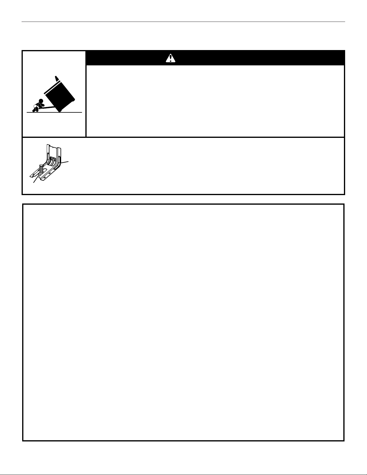
48
Soporte antivuelco
La estufa no se volcará durante el uso normal. Sin embargo, se puede volcar si se aplica demasiada fuerza o peso sobre la puerta
abierta sin tener el soporte antivuelco adecuadamente sujeto al piso.
Peligro de Vuelco
Un niño o un adulto puede volcar accidentalmente la estufa y resultar muerto.
Verifique que se haya instalado y asegurado debidamente el soporte anti-vuelco según las
instrucciones de instalación.
Si traslada de lugar la estufa, vuelva a asegurar el soporte anti-vuelco.
No ponga a funcionar la estufa sin tener el soporte anti-vuelco instalado y asegurado.
No seguir estas instrucciones puede ocasionar la muerte o quemaduras graves en niños y
adultos.
Para verificar que el soporte anti-vuelco esté instalado y asegurado:
• Deslice la estufa hacia adelante.
• Verifique que el soporte anti-vuelco esté bien sujeto al piso o a la pared.
• Deslice la estufa hacia atrás de modo que la pata trasera quede debajo del soporte
anti-vuelco.
• Consulte las instrucciones de instalación para ver más detalles.
ADVERTENCIA
Soporte
anti-vuelco
Pata de la estufa
GUARDE ESTAS INSTRUCCIONES
INSTRUCCIONES IMPORTANTES DE SEGURIDAD
ADVERTENCIA: Para reducir el riesgo de incendio,
electrocución, lesiones a personas o daños al usar la estufa,
siga precauciones básicas, incluyendo las siguientes:
■ ADVERTENCIA: PARA REDUCIR EL RIESGO DE
VUELCO DE LA ESTUFA, ÉSTA DEBE ASEGURARSE
MEDIANTE LA INSTALACIÓN DEBIDA DE
DISPOSITIVOS ANTIVUELCO. PARA VERIFICAR SI
LOS DISPOSITIVOS ESTÁN DEBIDAMENTE
INSTALADOS, DESLICE LA ESTUFA HACIA DELANTE,
CERCIÓRESE DE QUE EL SOPORTE ANTIVUELCO
ESTÉ BIEN SUJETO AL PISO O A LA PARED Y
DESLICE LA ESTUFA HACIA ATRÁS DE MANERA QUE
LA PATA TRASERA DE LA ESTUFA QUEDE FIJA
DEBAJO DEL SOPORTE ANTIVUELCO.
■ ADVERTENCIA: NUNCA use este electrodoméstico
como calefactor de ambientes para calentar o entibiar la
habitación. El hacerlo puede resultar en la intoxicación con
monóxido de carbono y el sobrecalentamiento del horno.
■ ADVERTENCIA: NUNCA cubra ranuras, orificios o
pasajes en la parte inferior del horno ni cubra una rejilla
entera con materiales tales como papel de aluminio. El
hacerlo bloquea el flujo de aire en el horno y puede causar
la intoxicación con monóxido de carbono. Los forros de
papel de aluminio también pueden atrapar el calor y
provocar un riesgo de incendio.
■
AVISO: No almacene artículos que interesen a los niños
en los armarios que están encima de una estufa o en el
respaldo de protección de una estufa - al trepar los niños
encima de la estufa para alcanzar algún objeto, podrían
lastimarse seriamente.
■
Instalación apropiada – Al instalar la estufa debe hacer la
conexión eléctrica a tierra de acuerdo con las normas
locales o, en ausencia de normas locales, con
el Código
Eléctrico Nacional (National Electrical Code), ANSI/NFPA
70
. Cerciórese que la instalación y puesta a tierra de la
estufa sean efectuadas adecuadamente por un técnico
competente.
■ Esta estufa está equipada con un enchufe de tres puntas
con contacto a tierra para su protección contra riesgo de
electrocución y debería enchufarse directamente a un
tomacorriente que tiene conexión a tierra. No corte ni quite
la punta para conexión a tierra de este enchufe.
■
Desconecte el suministro de energía antes de dar
mantenimiento.
■
El mal uso de las puertas o cajones del aparato
electrodoméstico, tales como pisar, recostarse o sentarse
en las puertas o cajones, puede ocasionar heridas.
■ Mantenimiento – Mantenga el área de la estufa despejada y
libre de materiales combustibles, gasolina y otros vapores y
líquidos inflamables.
■
Almacenaje dentro o encima de la estufa – No se debe
almacenar materiales inflamables en el horno o cerca de las
unidades que están en la superficie.
■ El tamaño de la llama del quemador superior debe ajustarse
de manera que no se extienda más allá de los bordes del
utensilio de cocina.
Para estufas de gas de limpieza automática –
■ Antes de efectuar la limpieza automática del horno – quite
la charola para asar y otros utensilios. Limpie todo derrame
excesivo antes de iniciar el ciclo de limpieza.
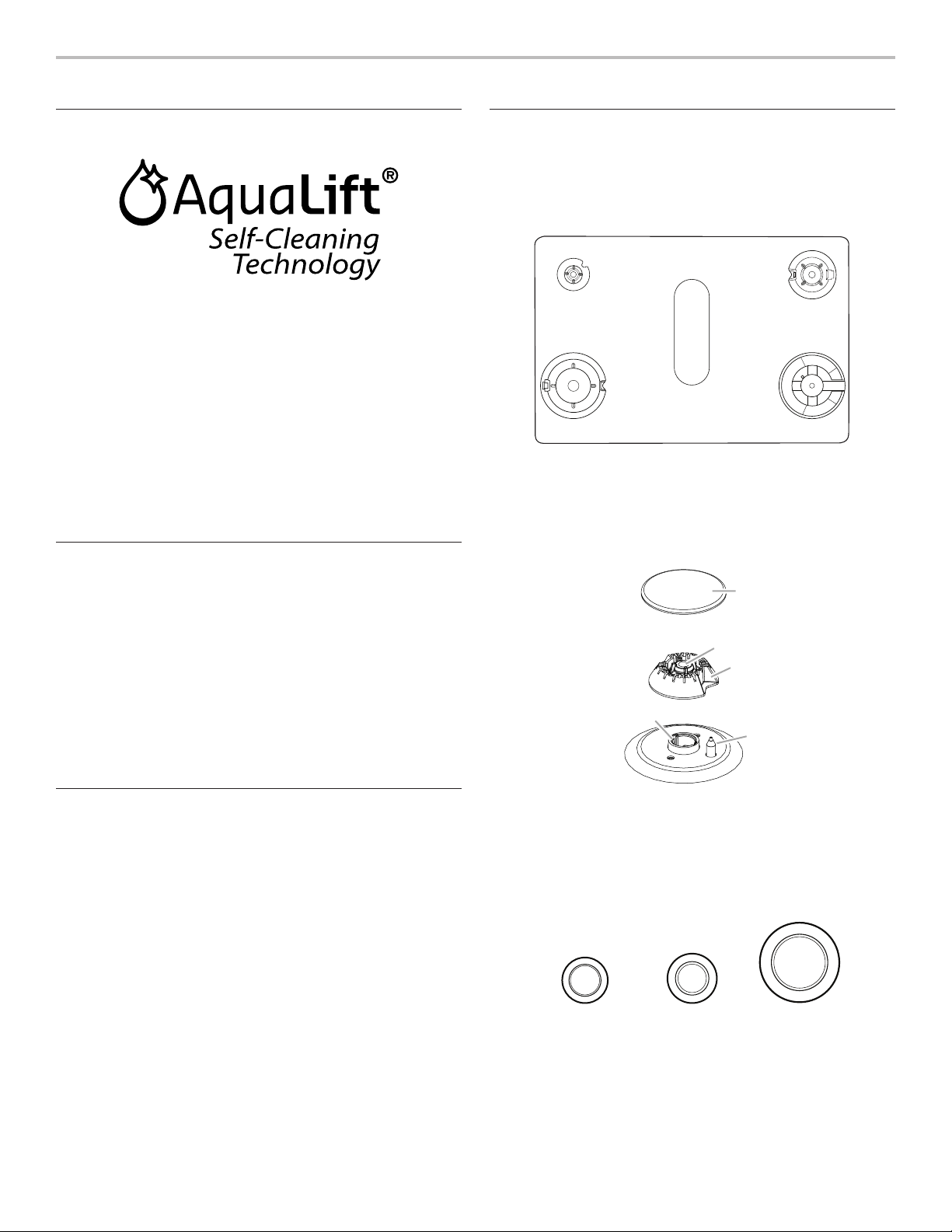
49
CONSEJOS DE USO ESENCIALES
Tecnología autolimpiante AquaLift
®
La tecnología autolimpiante AquaLift
®
es una solución de
limpieza de primera clase diseñada para minimizar el tiempo,
la temperatura y los olores que comúnmente conllevan los
métodos autolimpiantes tradicionales. Con la tecnología
autolimpiante AquaLift
®
un revestimiento innovador del interior
del horno se activa con calor y agua para aflojar la suciedad
quemada adherida. Para usar la tecnología autolimpiante
AquaLift
®
, simplemente repase los restos sueltos, vuelque agua
en el piso del horno y haga funcionar el ciclo autolimpiante
AquaLift
®
. Cuando el ciclo finaliza en menos de 1 hora a una
temperatura inferior a la de métodos autolimpiantes tradicionales,
simplemente recoja el agua restante y los restos sueltos. Vea
la sección “Ciclo de limpieza” para obtener instrucciones más
detalladas. Para información adicional, preguntas frecuentes y
videos sobre el uso de la tecnología autolimpiante AquaLift
®
,
visite nuestro sitio web en http://whirlpoolcorp.com/aqualift.
Temperaturas de la supercie
Cuando la estufa está en uso, todas las superficies pueden
calentarse, incluidas las perillas y la puerta del horno.
Cajón de calentamiento o almacenamiento
Cuando el horno está funcionando, es posible que el cajón se
caliente. No guarde en el cajón objetos de plástico, paños ni
otros objetos que pudieran derretirse o quemarse.
Ducto de escape del horno
La ventilación del horno libera aire caliente y humedad del horno
y no debe bloquearse ni taparse. No coloque objetos de plástico,
papel ni otros objetos que puedan derretirse o quemarse cerca
de la ventilación del horno.
Precalentamiento
Cuando comience un ciclo de horneado, horneado por
convección o asado por convección, el horno empezará a
precalentarse después de que se presione la tecla Start (Inicio).
El horno tardará 12 a 15 minutos aproximadamente para alcanzar
177 °C (350 °F) con todas las parrillas de horno provistas con el
horno dentro de la cavidad. Cuanto mayor sea la temperatura,
más tiempo tardará el horno en precalentarse. El ciclo de
precalentamiento aumenta rápidamente la temperatura del
horno. La temperatura real del horno superará la temperatura
fijada para compensar la pérdida de calor cuando se abra la
puerta del horno para introducir los alimentos. Esto asegura que
el horno comience a la temperatura correcta cuando se coloquen
los alimentos en el horno. Introduzca los alimentos cuando
suene el tono de precalentamiento. No abra la puerta durante el
precalentamiento antes de que suene el tono.
Quemadores de supercie
Las bases y las tapas de los quemadores deben estar
correctamente ubicadas antes de cocinar. La estufa viene con
tres tamaños de quemadores y de tapas. La base de cada
quemador redondo tiene marcada una letra que indica el tamaño
del quemador. Alinee las bases de los quemadores como se
muestra en la ilustración siguiente:
Alinee la abertura del tubo de gas en la base de los quemadores
con el soporte de orificio en la superficie de cocción y el
electrodo encendedor con la muesca en la base de los
quemadores.
La tapa de cada quemador redondo tiene marcada una letra
que indica el tamaño del quemador. Coloque las tapas de los
quemadores sobre las bases de los quemadores apropiados.
AUX
SR
UR
Tapa pequeña
(AUX)
Tapa mediana
(SR)
Extragrande
(UR)
A
D
EB
A. Small (S)
B. Large (L)
C. Oval D. Medium (M)
E. Large (L)
C
A. Pequeño (AUX)
B. Extragrande (UR)
C. Mediano D. Mediano (SR)
E. Wok
A
B
C
D
E
A. Tapa del quemador
B. Abertura del tubo de gas
C. Base del quemador
D. Electrodo encendedor
E. Soporte de orificio
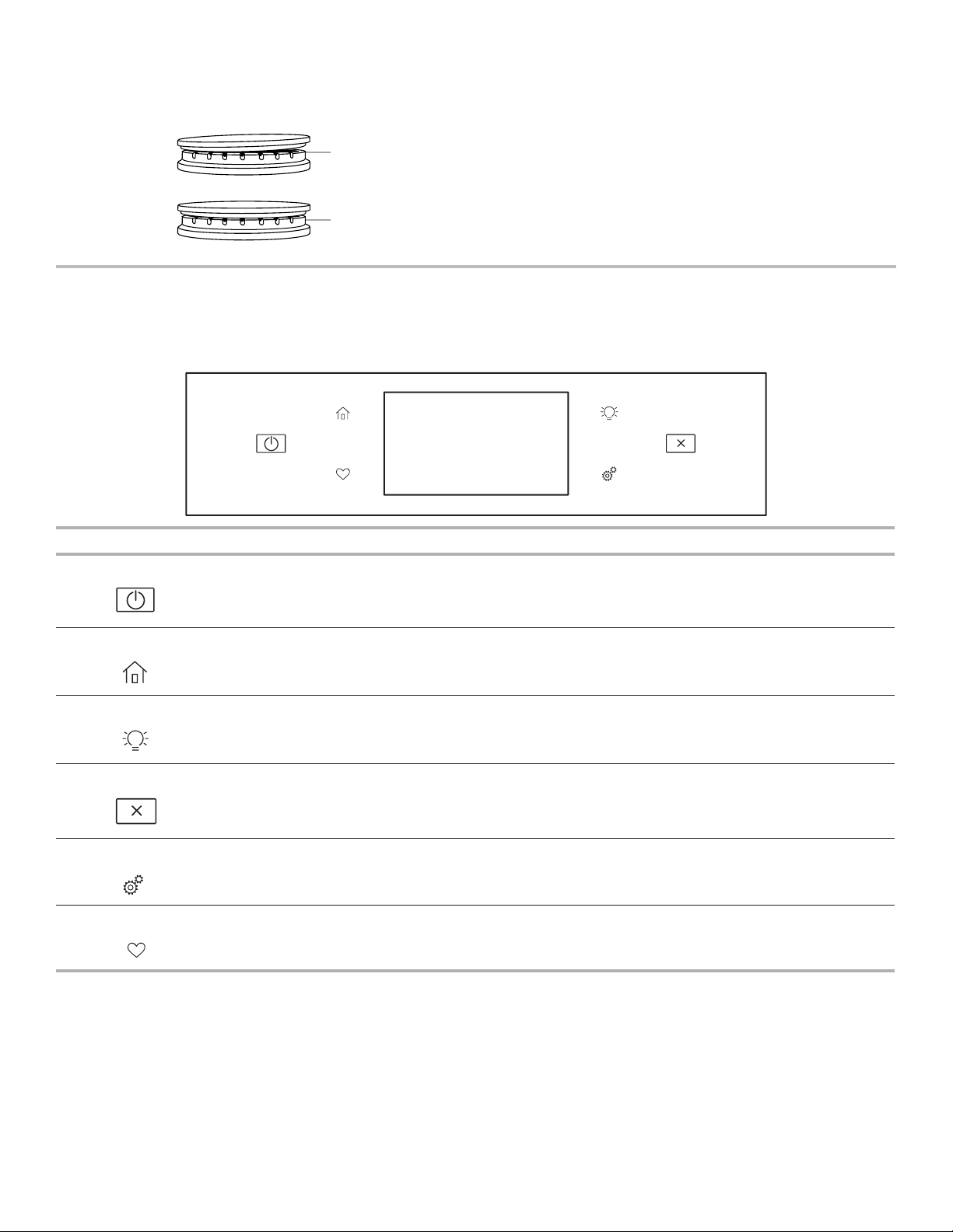
50
Las tapas de los quemadores deben estar niveladas cuando se
colocan en la posición correcta. Si las tapas de los quemadores
no están en la posición correcta, los quemadores de la superficie
no se encenderán. La tapa de los quemadores no debe oscilar ni
tambalearse si está debidamente alineada.
GUÍA DE FUNCIONES
Estas instrucciones describen varios modelos; Su modelo puede contar con algunos o todos los elementos enumerados. Consulte
estas instrucciones o la sección de preguntas frecuentes (FAQ) de nuestro sitio web en www.whirlpool.com para obtener
instrucciones más detalladas. En Canadá, visite nuestro sitio web en www.whirlpool.ca.
A
B
A. Incorrecto
B. Correcto
Tecla Función Instrucciones
Oven Power Función de
activación del
horno
La tecla de encendido del horno inicia la función del horno y lo activa si está en modo de
suspensión.
Home Pantalla inicial
Si se presiona una vez, permite al usuario volver a las pantallas “Métodos de cocción” y
“Cocción asistida”. Si se presiona dos veces, se muestra la hora del día.
Luz del horno Luz de la cavidad
del horno
La luz del horno se controla con una tecla situada en el panel de control del horno.
Mientras la puerta del horno está cerrada, presione el botón de la luz del horno para
encender y apagar la luz. Cuando se abre la puerta del horno, la luz interior se enciende
automáticamente.
Oven Cancel Función de
cancelación del
horno
La tecla de cancelación del horno detiene todas las funciones del horno, con excepción de
Clock (Reloj), Timer (Temporizador) y Control Lock (Bloqueo de control).
Herramientas Funciones para
usar el horno
Permite adaptar los tonos audibles y el funcionamiento del horno a sus necesidades. Vea la
sección “Herramientas" y "Más modos”.
Favorites Pantalla de
favoritos
La tecla de favoritos permite al usuario guardar y buscar los ciclos que utiliza con frecuencia.
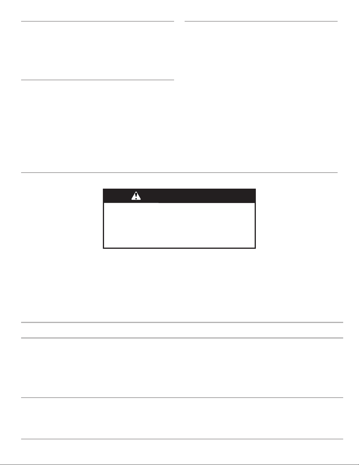
51
Panel táctil
El panel de control aloja el menú de control y los controles de las
funciones. Las teclas táctiles son muy sensibles y se activan con
un toque ligero.
Desplácese hacia arriba, abajo, derecha o izquierda para explorar
las distintas opciones y funciones.
Para obtener más información acerca de los controles
individuales, consulte las secciones respectivas en este manual.
Pantalla
La pantalla contiene los controles de las funciones de menú y del
horno. La pantalla táctil permite desplazarse por los menús del
horno. La pantalla es muy sensible y se activa y controla con un
toque ligero.
Cuando se utiliza el horno, la pantalla muestra el reloj, el modo, la
temperatura del horno, el temporizador de cocina y el del horno,
si se ha ajustado. Si no se ajustó el temporizador del horno,
puede hacerlo en esta pantalla.
Después de unos 2 minutos de inactividad, la pantalla entra en el
modo de reposo y su brillo se atenúa. Cuando el horno está en
funcionamiento, la pantalla permanece encendida.
Durante el uso, la pantalla muestra los menús y las selecciones
adecuadas para las opciones elegidas.
Desplazamiento por la pantalla
Si el horno está apagado, toque la tecla Home (Pantalla inicial)
para activar el menú. En esta pantalla pueden activarse todos los
programas de cocción automática; puede programarse toda la
cocción manual; pueden regularse as opciones y se tiene acceso
a las instrucciones, formas de preparación y consejos.
Métodos de cocción
La tecla Cooking Methods (Métodos de cocción) permite que el usuario seleccione uno de los métodos siguientes según las
necesidades de cocción:
■ Bake (Hornear)
■ Broil (Asar a la parrilla)
■ Convect Bake (Hornear por convección)
■ Convect Broil (Asar a la parrilla por convección)
■ Convect Roast (Asar por convección)
■ Keep Warm (Mantener caliente)
Forma de uso:
1. Toque la tecla Home (Pantalla inicial).
2. Seleccione la tecla Cooking Methods (Método de cocción).
3. Seleccione el método de cocción que desee.
ADVERTENCIA
Peligro de Intoxicación Alimentaria
No deje sus alimentos en el horno por más de una hora
antes o después de su cocción.
No seguir esta instrucción puede ocasionar
intoxicación alimentaria o enfermedad.
Método de
cocción
Función Instrucciones
BAKE (Hornear) Hornear y asar
1. Seleccione BAKE (Hornear).
2. Seleccione la temperatura que desee desplazándose a izquierda o derecha, o
manualmente, seleccionando la parrilla en la esquina superior derecha e introduciendo la
temperatura de horneado en el teclado.
3. Seleccione Start (Inicio) para empezar a precalentar. Suena una señal al terminar el
precalentamiento.
4. (Opcional) Para precalentar el horno con rapidez, vea la sección “Rápido” para buscar más
información en esta sección.
5. Presione la tecla Cancel (Cancelar) cuando haya finalizado.
BROIL (asado a
la parrilla)
Asar a la parrilla
1. Seleccione BROIL (Asar a la parrilla).
2. Seleccione la temperatura que desee desplazándose a izquierda o derecha, o
manualmente, seleccionando la parrilla en la esquina superior derecha e introduciendo la
temperatura de asado a la parrilla en el teclado.
3. Seleccione Start (Inicio) para empezar a asar a la parrilla.
4. Presione la tecla Cancel (Cancelar) cuando haya finalizado.

52
Método de
cocción
Función Instrucciones
CONVECT
BAKE (Hornear
por convección)
Horneado por
convección
1. Seleccione CONVECT BAKE (horneado por convección).
2. Seleccione la temperatura que desee desplazándose a izquierda o derecha, o
manualmente, seleccionando la cuadrícula en la esquina superior derecha e introduciendo
la temperatura de horneado por convección en el teclado.
3. Seleccione Start (Inicio) para empezar a precalentar. Sonará un pitido cuando el
precalentamiento esté completo.
4. (Opcional) Para precalentar el horno con rapidez, vea la sección “Rápido” para buscar más
información en esta sección.
5. Presione la tecla Cancel (Cancelar) cuando haya finalizado.
Para obtener más información, consulte la sección “Cocción por convección”.
CONVECT
BROIL (Asar a
la parrilla por
convección)
Asado a la parrilla
por convección
1. Seleccione CONVECT BROIL (asado a la parrilla por convección).
2. Seleccione la temperatura que desee desplazándose a izquierda o derecha, o
manualmente, seleccionando la parrilla en la esquina superior derecha e introduciendo la
temperatura de asado a la parrilla por convección en el teclado.
3. Seleccione START (Inicio).
4. Presione la tecla Cancel (Cancelar) cuando haya finalizado.
Para obtener más información, consulte la sección “Cocción por convección”.
CONVECT
ROAST (asado
por convección)
Asado por
convección
1. Seleccione CONVECT ROAST (asado por convección).
2. Seleccione la temperatura que desee desplazándose a izquierda o derecha, o
manualmente, seleccionando la cuadrícula en la esquina superior derecha e introduciendo
la temperatura de asado por convección en el teclado.
3. Seleccione START (Inicio).
4. Presione la tecla Cancel (Cancelar) cuando haya finalizado.
Para obtener más información, vea la sección “Cocción por convección”.
KEEP WARM
(Mantener
caliente)
Mantener
caliente
Los alimentos deberán estar a la temperatura para ser servidos antes de colocarlos en el horno
calentado.
1. Seleccione KEEP WARM (Mantener caliente).
2. Seleccione la temperatura que desee desplazándose a izquierda o derecha, o
manualmente, seleccionando la parrilla en la esquina superior derecha e introduciendo la
temperatura que desee en el teclado.
3. Presione START (Inicio).
4. Presione la tecla Cancel (Cancelar) cuando haya finalizado.
RAPID (rápido) Precalentamiento
rápido del horno
Proporciona el tiempo de precalentamiento más rápido para la función de horneado. El
Precalentamiento rápido está prefijado como apagado.
1. Seleccione RAPID (rápido) para alternar entre el encendido y el apagado del
precalentamiento rápido.
2. Aparecerá el ajuste actual.
IMPORTANTE: Esta función debe usarse solamente para hornear con una parrilla. Las parrillas
que no se usen deberán retirarse antes de utilizar el precalentamiento rápido. Deberá usarse
una parrilla estándar para Precalentamiento rápido.
Si ya ha comenzado a precalentarse el horno para el ciclo de horneado, puede ponerse en
marcha el precalentamiento rápido si se selecciona RAPID (Rápido).
START TIME
(Hora de inicio)
Inicio diferido
El inicio diferido se utiliza para ingresar la hora en la que se va a activar una función del horno
con inicio diferido. No debe usarse el inicio diferido con alimentos como panes y bizcochos, ya
que tal vez no se horneen correctamente.
COOK TIME
(Tiempo de
cocción)
Cocción
programada
La función Cook Time (Tiempo de cocción) permite que el horno se programe para
encenderse a una determinada hora del día, durante un tiempo establecido y/o se apague
automáticamente.

53
Cocción asistida
Para abreviar los pasos de preparación para la cocción, el
horno cuenta con la tecnología Frozen Bake™, que omite
el precalentamiento para algunas categorías de alimentos
congelados, Eso incluye: Pizza (Pizza), Lasagna (Lasaña),
Nuggets/fries (Croquetas/patatas fritas), Pies (Pays) y Meal
(Comida). Los alimentos se deben introducir de inmediato.
Recorra el menú de Cocción asistida hasta llegar a la opción de
alimento que desee.
Siga las indicaciones en pantalla para personalizar los ajustes de
Cocción asistida.
Favoritos
La función Favoritos almacena el modo y la temperatura del
horno de sus recetas favoritas.
NOTA: Es posible que la pantalla inicial muestre
automáticamente un conjunto seleccionado de favoritos y
recomendaciones basado en sus tiempos de cocción.
Para guardar una receta, seleccione la tecla Favorites (Favoritos,
icono con un corazón) y siga las instrucciones en pantalla para
personalizar sus favoritos.
Añada una imagen o asigne nombre al favorito para
personalizarlo de acuerdo con sus preferencias.
Herramientas
La tecla Herramientas permite acceder a funciones y opciones
de personalización del horno. Con dichas herramientas puede
ajustar el reloj, cambiar la temperatura del horno entre Fahrenheit
y Celsius, activar o desactivar las señales y mensajes sonoros,
ajustar la calibración del horno o cambiar el idioma, entre otras
cosas.
Seleccione la tecla Herramientas para ver sus funciones:
Para obtener más información, consulte la sección “Otros
modos”.
Herramienta Notas
Habilitación
remota
Seleccione Habilitación remota para utilizar
la aplicación Whirlpool
®
.
NOTA: La Habilitación remota se apaga
cuando se abre la puerta del horno. Se debe
reactivar cada vez que se vaya a utilizar.
Kitchen Timer
(temporizador
de cocina)
Ajuste el temporizador de cocina
manualmente con la introducción del tiempo
que desee en el teclado.
1. Seleccione Kitchen Timer (temporizador
de cocina).
2. Introduzca manualmente la duración que
desee.
3. Seleccione START (Inicio).
4. Seleccione Cancel (Cancelar) para
detener el temporizador de cocina.
Luz
Seleccione Luz para encender o apagar la
luz. Cuando se abre la puerta del horno, la
luz interior se enciende automáticamente.
Autolimpieza
Vea la sección “Cuidado de la estufa”.
Silencio
Seleccione Silencio para silenciar o activar
los sonidos del horno.
Bloqueo de
controles
Con Control Lock (Bloqueo de control)
se desactivan las teclas del panel de
control para evitar el uso accidental de los
hornos. Si se ajusta antes de un corte de
electricidad, la tecla Control Lock (Bloqueo
de control) seguirá activada después
del corte. Cuando los controles están
bloqueados, solo funcionan las teclas de
Encendido del horno, Herramientas y Luz
del horno.
El valor predeterminado de Control Lock
(bloqueo de controles) es desactivado, pero
puede activarse.
Para bloquear/desbloquear los controles:
1. Verifique que el horno esté apagado.
2. Seleccione la tecla “Control Lock”
(bloqueo de controles).
3. Se muestra “Control Lock” (bloqueo de
controles).
4. Desplace hacia arriba para desbloquear.
Cuando los controles estén bloqueados, no
funcionará ninguna tecla. Las funciones de
la superficie de cocción no se ven afectadas
por el bloqueo del control del horno.

54
Más modos
Modo Sabbath
Para buscar orientación sobre el uso y una lista completa de
modelos con modo Sabbath (modo de día de descanso), visite
www.star-k.org.
El modo Sabbat programa el horno para que permanezca
encendido en un ajuste de hornear hasta que se desconecte.
Cuando se activa el modo Sabbat, solo funciona el ciclo Bake
(hornear). Todos los demás ciclos de cocción y limpieza estarán
deshabilitados. No sonará ningún tono y la pantalla no indicará
los cambios de temperatura. Cuando se abra o se cierre la puerta
del horno, la luz no se encenderá ni apagará, y los elementos de
calentamiento no se encenderán ni apagarán inmediatamente.
Si hay un temporizador de cocción ajustado, no aparecerá la
cuenta regresiva. El temporizador aparecerá congelado en la
hora ajustada.
NOTA: Si ocurre una falla de energía mientras el modo de
descanso está en funcionamiento, el horno mostrará el modo
de descanso encendido, pero el ciclo de horneado no estará
encendido. Si se abre la puerta del horno durante este periodo, la
luz del horno se encenderá.
Para activar y desactivar el modo Sabbath:
1. Presione la tecla Tools (herramientas.
2. Seleccione More Modes (otros modos).
3. Seleccione Sabbath Mode (modo Sabbat).
4. Vuelva a presionar Sabbath Mode (modo Sabbat) para
activarlo (este modo está prefijado como desconectado).
5. Seleccione Yes (Sí) si desea que el horno esté encendido y
hornee durante el día de descanso.
6. Introduzca la temperatura deseada.
(Opcional) Para la cocción temporizada en modo de
descanso, presione ADD A COOK TIME (Agregar un tiempo
de cocción) para el horno seleccionado. Introduzca el tiempo
de cocción deseado y, después, presione NEXT (Siguiente).
7. Seleccione START (Inicio).
Para desactivar y salir del modo Sabbath (de día de
descanso):
Mantenga presionada la pantalla durante tres segundos.
Para regular la temperatura:
1. Presione +/- 25 en la pantalla para seleccionar la nueva
temperatura.
NOTA: El ajuste de temperatura no aparecerá en la pantalla y no
sonará ningún tono.
Calibración de la temperatura
IMPORTANTE: No use un termómetro para medir la temperatura
del horno. Los elementos se encenderán y se apagarán según
sea necesario para mantener una temperatura uniforme, pero
es posible que funcione en algún momento ligeramente caliente
o frío a causa de este ciclo. La apertura del horno afecta a los
ciclos de los elementos y a la temperatura.
El horno proporciona temperaturas precisas y se ha sometido a
pruebas exhaustivas en la fábrica. Sin embargo, puede cocinar
más rápido o más lento que su horno anterior, con diferencias de
horneado o de dorado final. Si es necesario, la calibración de la
temperatura se puede ajustar en grados Fahrenheit o Celsius.
Un signo menos significa que el horno estará más frío con el
valor que se muestra en la pantalla. La ausencia de signo menos
significa que el horno estará a temperatura más caliente con el
valor que aparece en la pantalla. Utilice la siguiente tabla como
guía.
NOTA: La pantalla del horno sigue mostrando el ajuste de
temperatura original y no refleja el cambio de calibración. Por
ejemplo, si está ajustado en 350° (177 °C) y se calibra a -20, la
pantalla seguirá mostrando 350° (177°C).
Regule la temperatura del horno hasta (+, -) 30 °F ([+, -]18 °C).
Se recomienda realizar cambios en tramos de 3 °C (5 °F) hasta
conseguir el resultado que se busca.
Para ajustar la calibración de la temperatura del horno:
1. Presione la tecla Tools (herramientas).
2. Seleccione More Modes (otros modos).
3. Seleccione Temperature Calibration (calibración de
temperatura).
4. Desplace de izquierda a derecha para aumentar o reducir la
temperatura.
Preferencias
Horas y fechas
Ajuste las preferencias de hora y fecha.
■ Sus horarios de comidas: Ajuste cuando aparezca
desayuno/almuerzo/cena
■ Hora
■ Fecha
■ Formato horario (AM/PM o 24 horas [horario militar])
NOTA: Si el usuario está conectado a una red Wifi, la hora y
la fecha se ajustan automáticamente.
Volumen de sonido
Ajuste las preferencias de volumen de sonido.
■ Temporizadores y alertas
■ Teclas y efectos
Ajustes de pantalla
Ajuste el brillo de la pantalla.
■ Brillo de la pantalla
Regional
Ajuste las preferencias regionales.
■ Idioma: inglés, español o francés
■ Unidades de temperatura: Fahrenheit y Celsius.
WiFi
■ Conéctese a la red: Descargue la aplicación Whirlpool
®
de la tienda de aplicaciones de su celular. Consulte la hoja
Configuración de la conectividad para obtener instrucciones
más detalladas.
■ Código SAID: El código SAID se utiliza para sincronizar un
dispositivo inteligente con el aparato. Introduzca el código
SAID en la aplicación Whirlpool
®
.
■ Dirección MAC: Se muestra la dirección MAC del módulo
WiFi.
■ Radio WiFi: Active o desactive la red WiFi.
Información
■ Servicio y asistencia: Muestra el número de modelo, los
datos de contacto de asistencia al cliente y diagnósticos.
■ Guardar modo demo: Seleccione Store Demo Mode para
activar o desactivar la demostración.
■ Restablecer fábrica: Devuelve el producto a los ajustes
originales de fábrica.
■ Condiciones del uso de WiFi: www.whirlpool.com/connect
■ Condiciones de uso del software
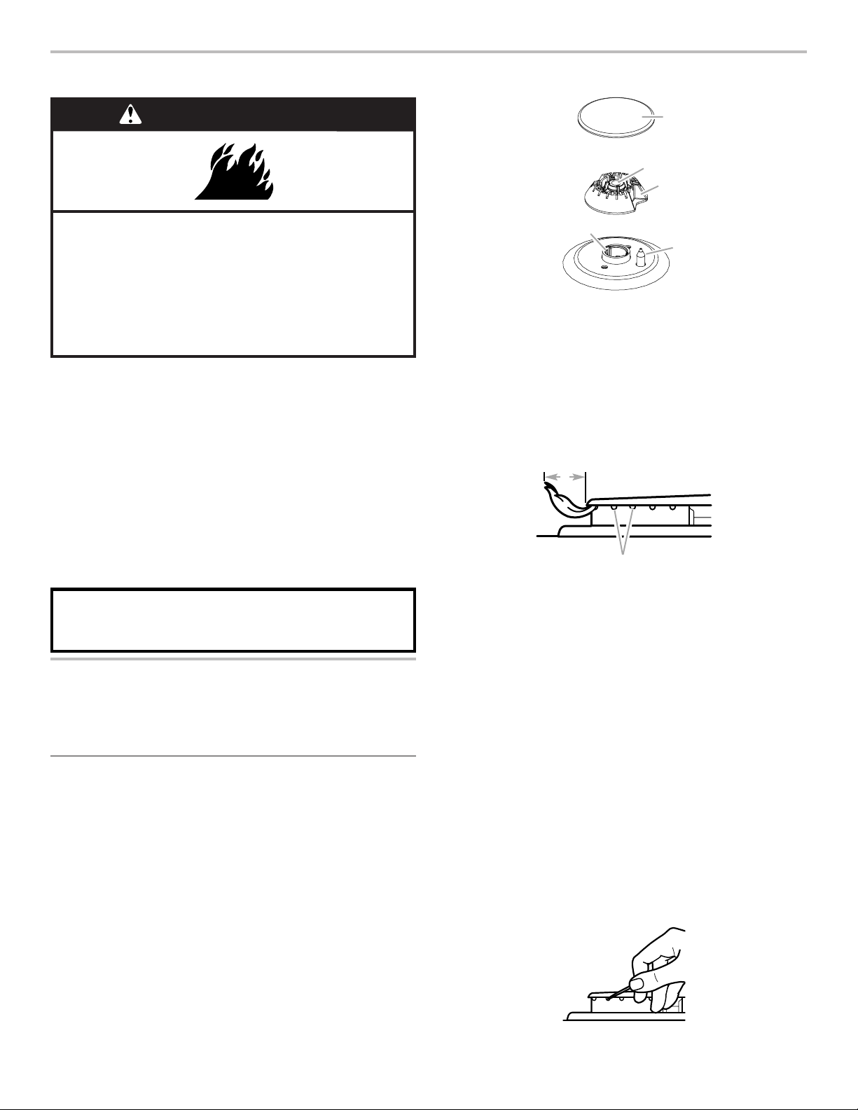
55
SUPERFICIE DE COCCIÓN
Los encendedores eléctricos encienden automáticamente los
quemadores de la superficie cuando las perillas de control se
giran hasta IGNITE (Encendido).
Coloque un utensilio de cocina lleno sobre la rejilla antes de
ajustar una perilla de control. No use un quemador con utensilios
de cocina vacíos o sin utensilios de cocina sobre la rejilla.
Para ajustar:
1. Empuje hacia adentro y gire la perilla en sentido antihorario
hasta IGNITE (Encendido).
Todos los quemadores de superficie harán un chasquido.
Solamente producirá una llama el quemador cuya perilla de
control esté girada hasta IGNITE (Encendido).
2. Gire la perilla a cualquier posición entre HIGH (Alto) y LOW
(Bajo).
Corte de corriente
En el caso de un corte de corriente prolongado, los quemadores
de la superficie pueden encenderse manualmente. Sostenga
un cerillo encendido cerca del quemador y gire la perilla en
sentido antihorario hasta IGNITE (Encendido). Después de que se
encienda el quemador, gire la perilla hasta el ajuste deseado.
Quemadores de supercie
IMPORTANTE: No obstruya el flujo de aire de combustión
y ventilación alrededor de los bordes de las rejillas de los
quemadores.
Tapa del quemador: Siempre mantenga la tapa del quemador en
su lugar cuando use un quemador de la superficie. Una tapa del
quemador limpia ayudará a prevenir el encendido deficiente y las
llamas desparejas. Siempre limpie la tapa del quemador después
de un derrame; quite y limpie periódicamente las tapas según la
sección “Limpieza general”.
NOTA: La base de cada quemador redondo tiene marcada una
letra que indica el tamaño del quemador.
Alineamiento: Asegúrese de alinear la abertura del tubo de
gas en la base del quemador con el soporte de orificio en la
superficie de cocción y el electrodo encendedor con la muesca
en la base del quemador.
NOTA: La base de cada quemador redondo tiene marcada una
letra que indica el tamaño del quemador.
Apertura del tubo de gas: Debe haber flujo libre de gas a través
de la abertura del tubo de gas para que el quemador se encienda
como es debido. Mantenga esa zona libre de suciedad y no
permita que ingresen derrames, comida, agentes de limpieza ni
otros materiales a la abertura del tubo de gas. Para mantener los
derrames lejos de la abertura del tubo de gas, siempre use una
tapa para el quemador.
Orificios de los quemadores: Revise las llamas de los
quemadores ocasionalmente para verificar que tengan el
tamaño y la forma adecuados, como se muestra en la ilustración
anterior. Una buena llama es de color azul, no amarillo. Mantenga
esa zona libre de suciedad y no deje que ingresen derrames,
alimentos, agentes de limpieza ni otros materiales en los orificios
de los quemadores.
Para limpiar:
IMPORTANTE: Antes de limpiar, asegúrese de que todos los
controles estén apagados y que la superficie de cocción esté fría.
No use limpiadores para horno, blanqueador ni productos para
quitar óxido. No lave en la lavavajillas.
1. Retire la tapa del quemador y la base del quemador y limpie
como se indica en la sección “Limpieza general”.
2. Limpie la abertura del tubo de gas con un paño húmedo.
3. Limpie los orificios del quemador obstruidos con un alfiler
recto, como se muestra. No agrande ni deforme el orificio.
No use un palillo de dientes de madera. Si se debe regular el
quemador, póngase en contacto con un especialista en
reparaciones capacitado.
Peligro de Incendio
No permita que la llama del quemador se extienda más
allá de la orilla de la cacerola.
Apague todos los controles cuando no esté cocinando.
No seguir estas instrucciones puede ocasionar
la muerte o incendio.
ADVERTENCIA
RECUERDE: Cuando se esté usando la estufa o (en
algunos modelos) durante el ciclo de autolimpieza, toda la
superficie de cocción se puede calentar.
A
B
C
D
E
A. Tapa del quemador
B. Abertura del tubo
de gas
C. Base del quemador
D. Electrodo
encendedor
E. Soporte de orificio
B
A
A. 1" a 1
1
/
2
" (2,5 cm a 3,8 cm)
B. Orificios de los quemadores
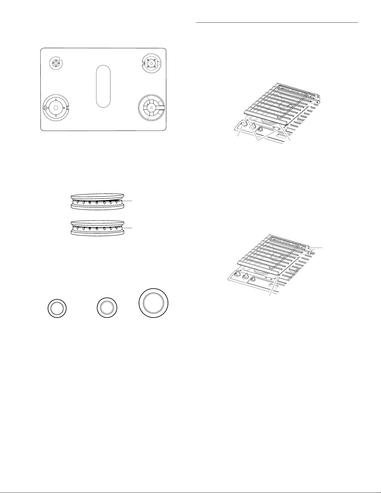
56
4. Vuelva a colocar la base del quemador. La base de cada
quemador redondo tiene marcada una letra que indica el
tamaño del quemador. Vea en la ilustración siguiente las
posiciones de los quemadores.
5. La tapa de cada quemador redondo tiene marcada una letra
que indica el tamaño del quemador. Vuelva a colocar la tapa
del quemador y asegúrese de que quede debidamente
alineada con la base del quemador. La tapa de los
quemadores no debe oscilar ni tambalearse si está
debidamente alineada.
IMPORTANTE: Las bases de las tapas pequeñas e
intermedias son distintas. No coloque una tapa de quemador
equivocada sobre la base del quemador.
AUX
SR
UR
Tapa pequeña (AUX) Tapa mediana (SR) Extragrande (UR)
6. Encienda el quemador. Si el quemador no se enciende,
verifique la alineación de la tapa. Si el quemador todavía
no se enciende, ciérrelo. No intente reparar el quemador
por su cuenta. Póngase en contacto con un especialista en
reparaciones capacitado.
Rejillas de la supercie
Las rejillas deben colocarse correctamente antes de cocinar.
Cuando están bien colocadas, las rejillas deben quedar al ras y
niveladas. La instalación incorrecta de las rejillas puede dar como
resultado desportillados o rayas en la superficie de cocción.
Para garantizar una colocación correcta, alinee los topes de la
parte inferior de las rejillas con las hendiduras de la superficie de
cocción.
Las rejillas de la superficie se fijan con el gancho de un extremo
de la rejilla y la hendidura del otro. Para extraer las rejillas, eleva
la parte trasera de la rejilla izquierda para soltar el gancho y, a
continuación, eleve la parte delantera de la rejilla derecha para
soltarla del gancho y extráigalas. Para volver a colocar las rejillas,
introduzca primero la rejilla izquierda. Coloque la hendidura
delantera de la rejilla derecha sobre el gancho de la rejilla
izquierda; a continuación, eleve la parte trasera de la rejilla
izquierda y coloque la hendidura sobre el gancho de la rejilla
derecha.
A pesar de que las rejillas de los quemadores son duraderas,
perderán gradualmente el brillo y/o cambiarán de color debido a
las altas temperaturas de la llama de gas.
A
D
EB
A. Small (S)
B. Large (L)
C. Oval D. Medium (M)
E. Large (L)
C
A. Pequeño (AUX)
B. Extragrande (UR)
C. Mediano D. Mediano (SR)
E. Wok
A
B
A. Incorrecto
B. Correcto
A
A
B
A. Topes
B. Hendiduras
de alineación
A
B
A. Gancho
B. Hendidura
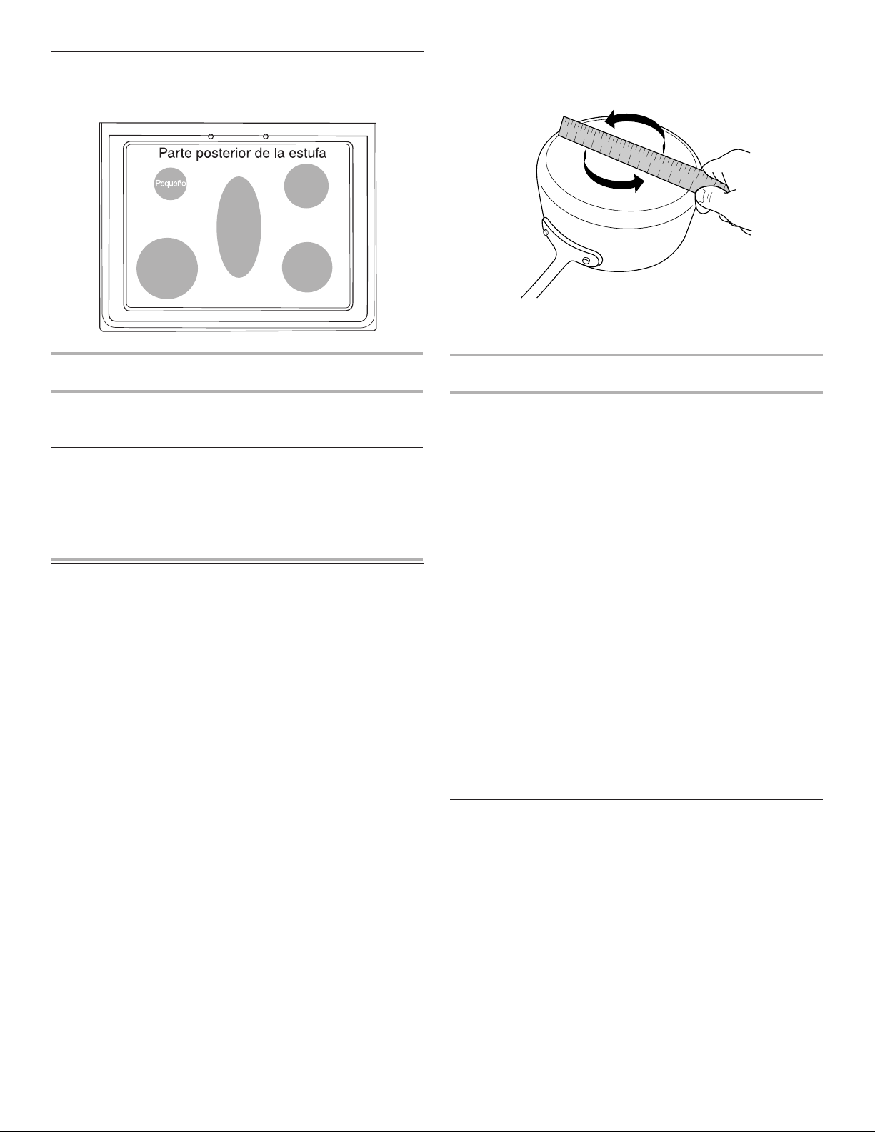
57
Tamaño del quemador
Seleccione un quemador cuyo tamaño sea el más adecuado
para el utensilio de cocina. Vea la ilustración y la tabla siguientes.
Tamaño del
quemador
Uso recomendado
Pequeño
■ Cocción con calor bajo
■ Para derretir chocolate o
mantequilla
Media
■ Quemador multiuso
Wok
■ Para utensilios de cocina
grandes
Extragrande (potencia
máxima)
■ Para utensilios de cocina
grandes
■ El quemador más potente
Utensilios de cocina
IMPORTANTE: No deje utensilios de cocina vacíos sobre una
zona de cocción, un elemento o un quemador de superficie que
estén calientes.
El utensilio de cocina ideal debe tener fondo plano, lados rectos,
una tapa que encaje bien y el material debe ser de grosor
mediano a pesado.
Los acabados ásperos pueden rayar la superficie de cocción
o las bobinas de encendido. El aluminio y el cobre pueden
usarse como centro o base del utensilio de cocina. Sin embargo,
cuando se usen como base pueden dejar marcas permanentes
en las superficies.
El material de los utensilios de cocina es un factor que influye en
la rapidez y la uniformidad con que se trasmite el calor, lo cual
afecta los resultados de la cocción. Un acabado antiadherente
tiene las mismas características que su material de base. Por
ejemplo, un utensilio de cocina de aluminio con un acabado
antiadherente tendrá las mismas propiedades que el aluminio.
No deben usarse utensilios de cocina con superficies
antiadherentes bajo el asador.
Verifique si está plano colocando el borde derecho de una regla a
lo largo del fondo del utensilio de cocina. Mientras rota la regla,
no debe verse espacio ni luz entre la regla y el utensilio de
cocina.
Utilice la siguiente tabla como guía para ver las características de
los materiales de los utensilios de cocina.
Utensilios de
cocina
Características
Aluminio
■ Se calienta de manera rápida y
uniforme.
■ Adecuado para todos los tipos de
cocción.
■ Los espesores medianos o pesados
son óptimos para la mayoría de los
trabajos de cocción.
■ Pueden dejar residuos de aluminio,
que se reducirán si se limpian
inmediatamente después de la
cocción.
Hierro fundido
■ Se calienta de manera lenta y
uniforme.
■ Es adecuado para dorar y freír.
■ Mantiene el calor para una cocción
lenta.
■ Los bordes ásperos o las rebabas
podrían rayar la superficie de cocción.
Cerámica
o vidrio de
cerámica
■ Siga las instrucciones del fabricante.
■ Calienta de manera lenta pero
desigual.
■ Da resultados ideales con los ajustes
de calor bajo a medio.
■ Podría rayar la superficie de cocción.
Grande
(con más
potencia)
Medio
Oval
Parte frontal de la estufa
Wok
1
2
3
4
5
6
7
8
9
1 0
1 1
1 2
1 3
1 4
1 5
1 6
1 7
1 8
1 9
2 0
1
2
3
4
5
6
7
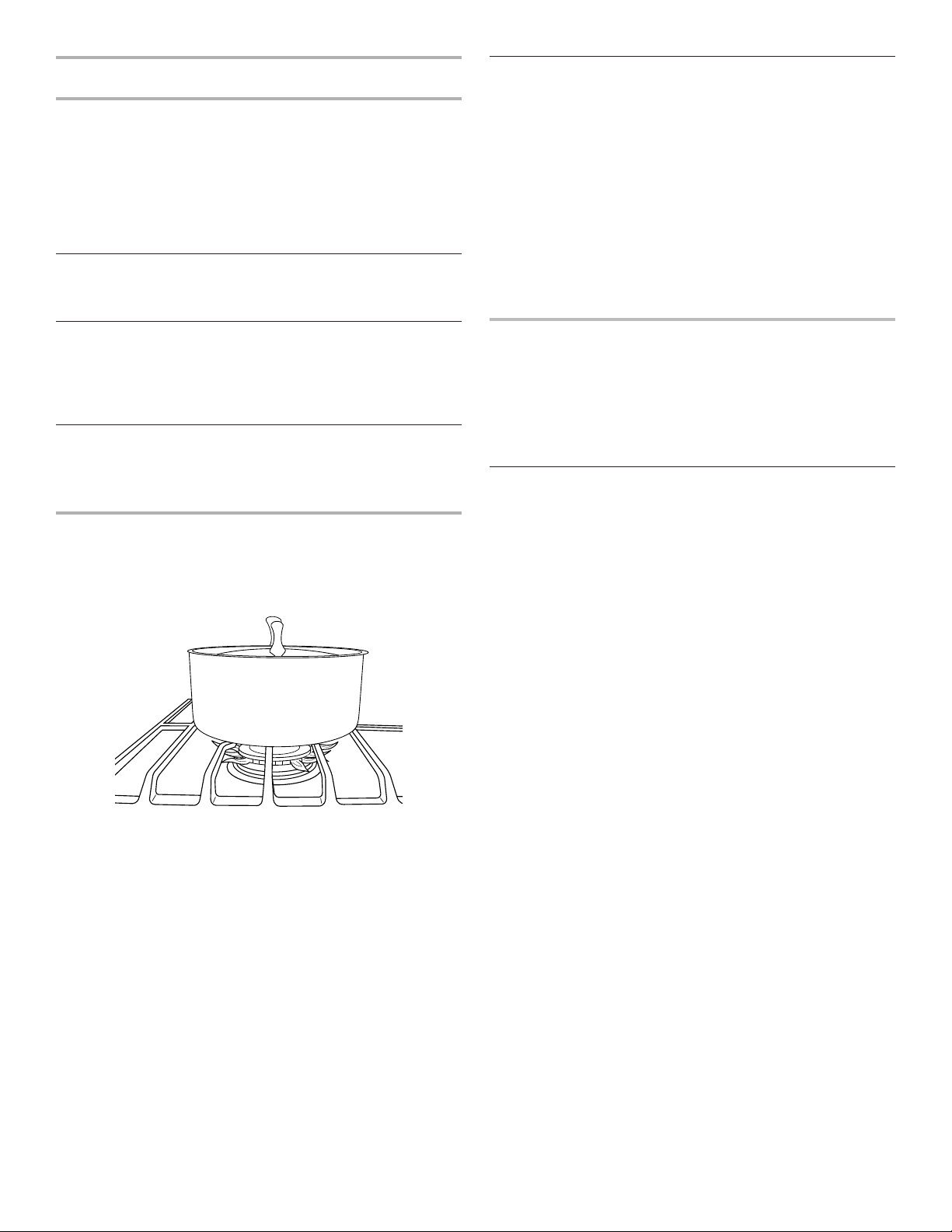
58
Utensilios de
cocina
Características
Cobre
■ Se calienta de manera rápida y
uniforme.
■ Puede dejar residuos de cobre,
que disminuirán si se limpia
inmediatamente después de la
cocción.
■ Puede dejar manchas o adherencias
permanentes en la superficie de
cocción si se calienta en exceso.
Barro cocido
■ Siga las instrucciones del fabricante.
■ Use con ajustes de calor bajos.
■ Podría rayar la superficie de cocción.
Hierro fundido o
acero esmaltado
■ Vea acero inoxidable o hierro fundido.
■ Los utensilios para hornear con
esmalte de porcelana que no tengan
la base de metal podrían pegarse a la
superficie de cocción si se calientan
en exceso.
Acero inoxidable
■ Se calienta de manera rápida pero no
uniforme.
■ Un centro o una base de aluminio
o cobre sobre acero inoxidable
proporciona un calor uniforme.
Use utensilios de cocina con fondo plano para lograr los mejores
resultados de cocción y un uso eficiente de energía. El recipiente
de cocción deberá ser aproximadamente del mismo tamaño que
el área de cocción delineada en la superficie de cocción o el
elemento de bobina. Los utensilios de cocina no deben superar
la zona o elemento de cocción más de 1/2" (13 cm).
Envasado casero
Cuando esté haciendo enlatados durante períodos largos, alterne
el uso de los quemadores de la superficie entre una tanda y otra.
Esto da tiempo para que se enfríen las zonas que se han usado
recientemente.
■ Centre el recipiente para envasado sobre la rejilla, encima del
quemador.
■ No coloque el recipiente para envasado sobre dos
quemadores de superficie a la vez.
■ Para obtener más información, póngase en contacto con la
oficina de extensión del departamento de agricultura local o
consulte guías para envasado casero publicadas. También
pueden ofrecer ayuda las compañías que fabrican productos
para envasado casero.
HORNO
Los olores y el humo son normales cuando el horno se usa las
primeras veces o cuando tiene suciedad profunda.
IMPORTANTE: La salud de algunos pájaros es sumamente
sensible a los gases emanados por el horno. La exposición a los
gases puede ocasionar la muerte de ciertos pájaros. Traslade
siempre los pájaros a otro cuarto cerrado y bien ventilado.
Papel de aluminio
IMPORTANTE: Para evitar daños permanentes en el acabado
de la base del horno, no lo cubra con ningún tipo de papel de
aluminio o revestimiento.
Para obtener resultados de cocción óptimos, no cubra toda
la parrilla del horno con papel de aluminio, ya que el aire debe
poder circular libremente.
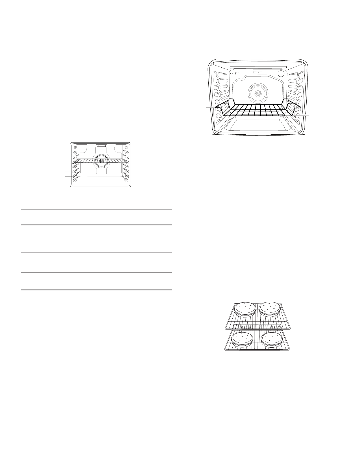
59
Colocación de las parrillas y los utensilios para hornear
IMPORTANTE: Para evitar daños permanentes en el acabado
de porcelana, no coloque alimentos ni utensilios para hornear
directamente sobre la puerta o el piso del horno.
Utensilios para hornear
Para una cocción uniforme del alimento, el aire caliente debe
poder circular. Deje 2" (5 cm) de espacio alrededor del utensilio
para hornear y las paredes del horno. Asegúrese de que ningún
utensilio para hornear esté directamente encima de otro.
Parrillas
■ Coloque las parrillas antes de encender el horno.
■ No coloque parrillas con utensilios para hornear encima.
■ Asegúrese de que las parrillas estén niveladas.
Para ubicar una parrilla, retírela hasta la posición de tope, levante
el borde delantero y luego sáquela. Use como guía la ilustración
y las tablas siguientes.
El horno tiene 7 posiciones para una parrilla plana, como se
muestra en la ilustración anterior y en la tabla a continuación.
Posición de parrilla
plana*
Tipo de alimento
7 Asar a la parrilla/dorar rápidamente
carnes, hamburguesas y filetes
6 Carnes, pollo y pescado asados a la
parrilla
3 o 4 La mayoría de los alimentos
horneados, guisados, alimentos
congelados
2 Carnes asadas
1 Asados o aves grandes
Para que las hamburguesas tengan un exterior bien dorado y un
interior a punto, use una parrilla plana en la posición de parrilla
7. Caliente previamente el horno durante 5 minutos. El lado 1
debe cocinarse durante aproximadamente 4 a 5 minutos. El lado
2 debe cocinarse durante aproximadamente 4
1
/
2
a 5
1
/
2
minutos.
Es normal que haya un grado moderado de humo cuando se asa
a la parrilla.
* Si su modelo tiene una parrilla de horno de máxima capacidad,
los extremos en relieve deberán colocarse en la posición de
parrilla por encima de la posición deseada para el alimento.
Vea la siguiente ilustración.
IMPORTANTE: Estas posiciones de parrilla son para las parrillas
planas. Si se usa una parrilla de horno de máxima capacidad,
la posición de la parrilla debe ajustarse como se muestra en la
figura anterior.
Cocción en varias parrillas
Dos parrillas (sin convección): Use las posiciones de parrilla
2 y 5 o 3 y 6.
Dos parrillas (con convección): Use las posiciones de parrilla
2 y 5 o 3 y 6.
Tres parrillas (con convección): Use las posiciones de parrilla
2 y 7 y una parrilla de horno de máxima capacidad en la posición
de parrilla 5.
Horneado de galletas y pasteles de capas en dos parrillas
Horneado de pasteles de capas
Para obtener resultados óptimos cuando se hornean pasteles en
dos parrillas, use la función Bake (Horneado), una parrilla plana
en la posición de parrilla 5 y una parrilla plana en la posición de
parrilla 2. Si no dispone de 2 parrillas planas, utilice una parrilla
de horno de máxima capacidad en la posición de parrilla 6.
Coloque los pasteles en las parrillas como se muestra. Deje un
espacio de al menos 3" (7,6 cm) entre la parte delantera de las
parrillas y los pasteles delanteros.
Horneado de galletas
Para obtener resultados óptimos cuando se hornean galletas
en 2 parrillas, use la función Convection Bake (Horneado por
convección), una parrilla plana en la posición de parrilla 5 y una
parrilla plana en la posición de parrilla 2.
Si no dispone de 2 parrillas planas, utilice una parrilla plana en
la posición 2 y una parrilla de horno de máxima capacidad en la
posición 6.
Si no dispone de la función Convection Bake (Horneado por
convección), utilice la función Bake (Horneado) estándar.
7
6
5
4
3
2
1
A
B
A. Extremos de la parrilla en la
posición 3
B. Alimento en la posición 2

60
Ventilación del horno
La ventilación del horno libera aire caliente y humedad del horno
y no debe bloquearse ni taparse; de lo contrario, se producirá
una circulación de aire deficiente que afectará los resultados de
la cocción y de la limpieza. No coloque objetos de plástico, papel
ni otros objetos que puedan derretirse o quemarse cerca de la
ventilación del horno.
Cómo hornear y asar
Precalentamiento
Cuando comience un ciclo de horneado u horneado por
convección, el horno empezará a precalentarse después de
que se presione la tecla Start (Inicio). El horno tardará 12 a
15 minutos aproximadamente para alcanzar 177 °C (350 °F)
con todas las parrillas de horno provistas con el horno dentro
de la cavidad. Cuanto mayor sea la temperatura, más tiempo
tardará el horno en precalentarse. El ciclo de precalentamiento
aumenta rápidamente la temperatura del horno. La temperatura
real del horno superará la temperatura fijada para compensar
la pérdida de calor cuando se abra la puerta del horno para
introducir los alimentos. Esto asegura que el horno comience
a la temperatura correcta cuando se coloquen los alimentos
en el horno. Introduzca el alimento cuando suene el tono de
precalentamiento. No abra la puerta durante el precalentamiento
antes de que suene el tono.
Precalentamiento rápido
Puede usarse Rapid Preheat (precalentamiento rápido)
para acortar el tiempo de precalentamiento. Deberá usarse
solamente una parrilla estándar plana para horno durante el
precalentamiento rápido. Las parrillas adicionales deben quitarse
antes de utilizar Rapid Preheat (Precalentamiento rápido). El
ciclo de precalentamiento debe completarse antes de colocar
los alimentos en el horno. Cuando se haya terminado el ciclo de
precalentamiento rápido, el horno pondrá en marcha un ciclo
normal de horneado.
IMPORTANTE: El precalentamiento rápido se debe utilizar
únicamente para hornear con una sola parrilla.
Temperatura del horno
Mientras esté en uso, los elementos del horno se encenderán
y se apagarán según sea necesario para mantener una
temperatura constante, pero es posible que funcione en algún
momento ligeramente caliente o frío a causa de este ciclo. Si se
abre la puerta del horno mientras se encuentra en uso, saldrá el
aire caliente y el horno se enfriará, lo que podría afectar el tiempo
y el rendimiento de la cocción. Se recomienda usar la luz del
horno para controlar el progreso de cocción.
NOTA: En los modelos con convección, el ventilador de
convección puede funcionar en el modo de horneado sin
convección para mejorar el rendimiento del horno.
Sistema de control de temperatura
El sistema de control de temperatura regula electrónicamente
los niveles de calor del horno durante el precalentamiento y el
horneado para mantener una temperatura precisa y obtener
resultados de cocción óptimos. Los elementos o quemadores
de hornear y asar a la parrilla tendrán ciclos con encendido y
apagado a intervalos. En los modelos de estufa con convección,
el ventilador funcionará durante el precalentamiento y es posible
que se encienda y apague durante intervalos breves durante el
horneado para producir resultados óptimos. Esta característica
se activa automáticamente cuando el horno está en uso.
Antes de hornear o asar, coloque las parrillas según la sección
“Posición de las parrillas y los utensilios para hornear”.
Al asar, no es necesario esperar a que termine el ciclo de
precalentamiento del horno antes de colocar los alimentos, a
menos que la receta de cocina lo recomiende.
Frozen Bake™
La tecnología Frozen Bake™ regula automáticamente el tiempo
de horneado fijado por el fabricante mediante la combinación
de precalentamiento y horneado con el fin de ofrecer excelentes
resultados con alimentos congelados envasados sin necesidad
de espera. Se pueden elegir seis opciones preprogramadas para
alimentos: Pizza (Pizza), Lasagna (Lasaña), Nuggets (Croquetas),
Fries (Patatas fritas), Pie (Pay) y Meal (Comida). Los ciclos Frozen
Bake™ se han adaptado para funcionar únicamente con estos
alimentos. Cuando se utilice la tecnología Frozen Bake™, es
importante seguir todas las instrucciones del fabricante respecto
a la ventilación, la cobertura, la agitación o la colocación en una
hoja de hornear para asegurar un resultado óptimo. Al cocinar
alimentos congelados, solo se deben cocinar los que contengan
instrucciones para cocinarlos en un horno convencional.
Coloque el recipiente en el centro de la parrilla y seleccione una
de las posiciones de parrilla recomendadas para el horneado
de congelados en la sección “Posición de las parrillas y los
utensilios para hornear” y hornee un solo paquete o charola
por vez. Utilice la temperatura y el tiempo de horneado máximo
recomendados en el paquete.
Un sonido le indicará que debe comprobar si los alimentos
están hechos antes de que se complete el tiempo de cocción
y nuevamente al finalizar el tiempo de cocción. La pantalla le
indicará que agregue tiempo de cocción si lo desea o que finalice
el ciclo.
Asado a la parrilla
Cuando ase a la parrilla, precaliente el horno durante 5 minutos
antes de colocar los alimentos, a menos que se recomiende otra
cosa en la receta. Coloque los alimentos sobre una rejilla en una
bandeja para asar y después ubíquelos en el centro de la parrilla
del horno.
IMPORTANTE: Cierre la puerta para garantizar una temperatura
adecuada para asar.
Para obtener un control más preciso al cocinar, cambie la
temperatura mientras esté asando. Cuanto más bajo sea el
ajuste de temperatura, más lenta será la cocción. Los cortes
más gruesos y las piezas de carne, pescado y aves con forma
irregular se pueden cocinar mejor con ajustes para asar a la
parrilla más bajos. Use las parrillas 6 o 7 para asar a la parrilla.
Consulte la sección “Posición de las parrillas y los utensilios para
hornear” para obtener más información.
Con los ajustes más bajos, el elemento para asar a la parrilla se
encenderá y se apagará para mantener la temperatura adecuada.
■ Para obtener resultados óptimos, utilice un recipiente para
asar y una rejilla. Se han diseñado para drenar los jugos y
evitar salpicaduras y humo.
Si desea comprar una charola para asar, puede hacer un
pedido.
A
A. Ventilación del horno
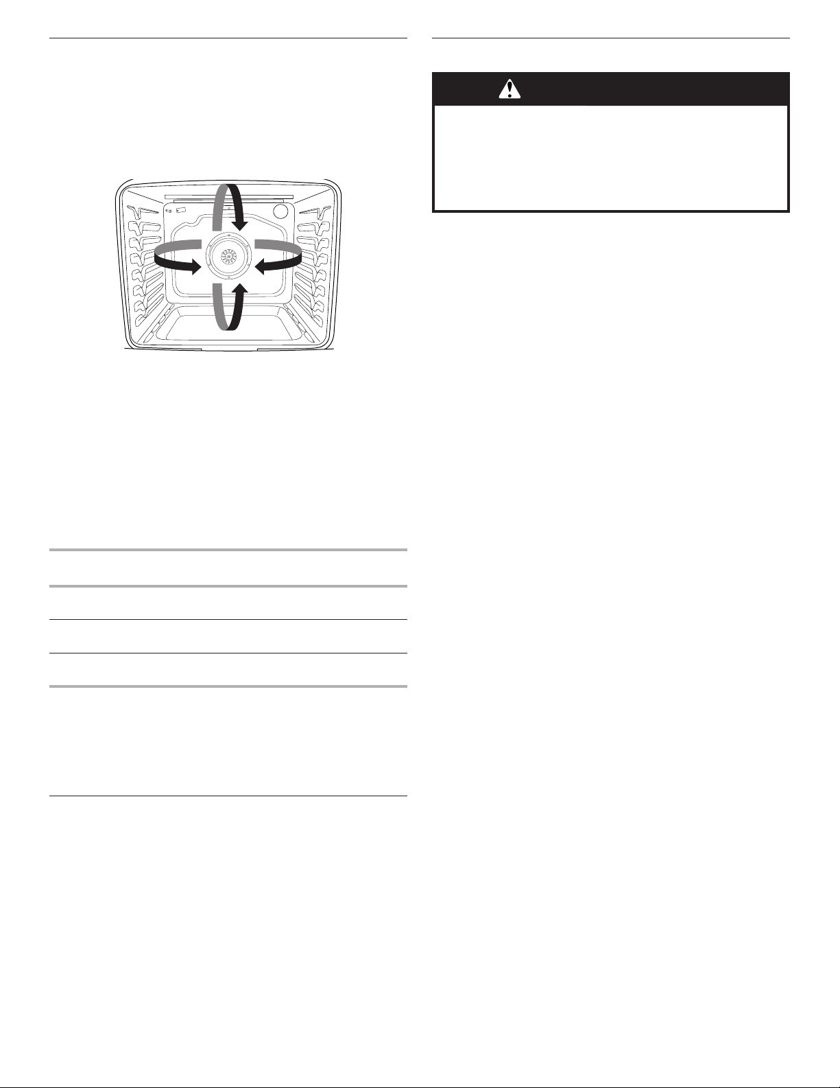
61
Cocción por convección
En un horno por convección, el aire caliente que hace circular el
ventilador distribuye el calor continuamente y con más
uniformidad que el movimiento natural del aire en un horno
térmico estándar. Este movimiento de aire caliente ayuda a
mantener una temperatura uniforme en todo el horno, cocina los
alimentos más uniformemente y deja las superficies crujientes a
la vez que atrapa la humedad y hace que los panes salgan con
cortezas más crujientes.
Durante el horneado o asado por convección, el ciclo de
horneado, asado a la parrilla y de los elementos de convección
se enciende y apaga a intervalos, mientras el ventilador
hace circular aire caliente. Durante el asado a la parrilla por
convección, el ciclo de los elementos de asado a la parrilla y
convección se enciende y apaga.
Si se abre la puerta del horno durante la cocción por convección,
el ventilador se apagará de inmediato. Se encenderá nuevamente
cuando se cierre la puerta del horno.
Por medio de la cocción por convección, la mayoría de los
alimentos puede cocinarse a una temperatura más baja y/o un
tiempo de cocción menor que en un horno térmico estándar.
Utilice la siguiente tabla como guía.
Modo de cocción
por convección
Indicaciones de Directrices
Horneado por
convección
Temperatura menor, 25°F (15°C), posible
reducción del tiempo de cocción
Asado por
convección
Reducción del tiempo de cocción en
hasta un 30%
Asado a la parrilla
por convección
Reducción del tiempo de cocción
Opciones de convección
Horneado por convección: horneado en varias parrillas para
galletas, bizcochos, panes, guisados, tartas, tortas y pasteles
Asar por convección: pollo o pavo entero, verduras, asados de
cerdo y de carne de res
Asar a la parrilla por convección: cortes más gruesos o piezas de
carne, pescado o ave de forma irregular
Luz del horno
La luz del horno es un foco estándar de 40 vatios para
electrodomésticos. Antes de cambiarlas, asegúrese de que el
horno y la superficie de cocción estén fríos y que las perillas de
control estén la posición Off (Apagado).
Para hacer un reemplazo:
1. Desenchufe la estufa o desconecte el suministro de energía.
2. Gire en sentido antihorario la cubierta de vidrio del foco en la
parte posterior del horno para retirarla.
3. Gire el foco a la izquierda para sacarlo del casquillo.
4. Vuelva a colocar el foco girando en sentido horario.
5. Vuelva a colocar la cubierta del foco girando en sentido
horario.
6. Enchufe la estufa o reconecte el suministro de energía.
Tiempo de cocción
Para fijar un tiempo de cocción:
1. Presione la tecla para cualquier función de cocción.
2. Presione las teclas numéricas para fijar la temperatura
deseada. Si la temperatura que se ingresó no está dentro del
rango de temperaturas permitidas, aparecerá la temperatura
predeterminada y sonarán tonos audibles. Ingrese una
temperatura dentro del rango permitido.
3. Presione COOK TIME (Tiempo de cocción) para el horno
seleccionado.
4. Presione las teclas numéricas para ingresar la duración del
tiempo de cocción.
5. Presione START (Inicio). El temporizador iniciará la cuenta
regresiva del tiempo de cocción una vez que el horno haya
terminado de precalentarse.
6. Presione la tecla CANCEL (Cancelar) para el horno
seleccionado y se borrará la pantalla.
Para ajustar un tiempo de cocción y tiempo de detención:
NOTA: Esta función no está disponible para el horneado por
convección y el asado por convección si se usa la función de
conversión de tiempo y temperatura para convección.
1. Presione la tecla para cualquier función de cocción.
2. Presione las teclas numéricas para fijar la temperatura
deseada. Si la temperatura que se ingresó no está dentro del
rango de temperaturas permitidas, aparecerá la temperatura
predeterminada y sonarán tonos audibles. Ingrese una
temperatura dentro del rango permitido.
3. Presione COOK TIME (Tiempo de cocción) para el horno
seleccionado.
4. Presione las teclas numéricas para ingresar la duración del
tiempo de cocción.
5. Presione STOP TIME (Hora de detención) para el horno
seleccionado.
6. Presione las teclas numéricas para ingresar la hora del día en
que se detendrá la cocción.
7. Presione START (Inicio).
El tiempo de inicio se calcula automáticamente. El horno se
encenderá automáticamente cuando haya alcanzado la hora
de inicio.
Cuando se llegue a la hora de detención, el horno se apagará
automáticamente.
8. Presione la tecla CANCEL (Cancelar) para el horno
seleccionado y se borrará la pantalla.
ADVERTENCIA
Peligro de Intoxicación Alimentaria
No deje sus alimentos en el horno por más de una hora
antes o después de su cocción.
No seguir esta instrucción puede ocasionar
intoxicación alimentaria o enfermedad.

62
CUIDADO DE LA ESTUFA
Ciclo de limpieza
La tecnología AquaLift
®
es una solución de limpieza innovadora
que utiliza calor y agua para aflojar los derrames quemados
adheridos en el horno en menos de 1 hora. Esta nueva tecnología
de limpieza presenta una alternativa de calor bajo y sin olor frente
a las opciones tradicionales de autolimpieza.
Deje que el horno se enfríe a temperatura ambiente antes de
usar el ciclo Clean (Limpieza). Si la temperatura de la cavidad
del horno es mayor que 200°F (93°C), aparecerá "Oven Cooling"
(Enfriamiento del horno) en la pantalla y el ciclo de limpieza no se
activará hasta que la cavidad del horno se haya enfriado.
Para limpiar:
1. Quite todas las parrillas y los accesorios de la cavidad del
horno y limpie el exceso de suciedad. Use un raspador de
plástico para quitar la suciedad fácil de retirar.
2. Vierta 1
3
/
4
tazas (14 oz [414 mL]) de agua destilada o filtrada
sobre el piso del horno vacío y cierre la puerta del horno.
IMPORTANTE: No use productos químicos ni otros aditivos
con el agua. No abra el horno durante el ciclo de limpieza. El
agua que está en el piso del horno está caliente.
3. Presione AQUALIFT SELF CLEAN (Autolimpieza Aqualift) y,
después, START (Inicio) en el panel de control del horno.
4. Espere 40 minutos para la limpieza y el enfriamiento. Se
escuchará un pitido cuando se haya terminado el ciclo Clean
(Limpieza).
5. Presione la tecla CANCEL (Cancelar) al final del ciclo. Se
puede presionar CANCEL (Cancelar) en cualquier momento
para detener el ciclo de limpieza.
6. Retire el agua residual y la suciedad que se aflojó con una
esponja o un paño de inmediato una vez que el ciclo de
limpieza esté completo. Gran parte de las 1
3
/
4
tazas (14 oz
[414 mL]) de agua permanecerá en el horno después de que
se complete el ciclo. Si todavía queda suciedad, deje una
pequeña cantidad de agua en el piso del horno para facilitar
la limpieza.
7. Si queda suciedad, quítela con una esponja para restregar
que no raye o un raspador de plástico. Se pueden hacer
funcionar ciclos de limpieza adicionales para ayudar a quitar
la suciedad rebelde.
IMPORTANTE: No use productos de limpieza para hornos.
El uso de sustancias químicas, incluso productos de limpieza
comerciales para hornos o estropajos de metal, puede causar
daños permanentes a la superficie de porcelana del interior del
horno.
NOTAS:
■ La estufa deberá estar nivelada para asegurarse de que toda
la superficie del piso de la cavidad del horno esté cubierta
con agua al comienzo del ciclo de Clean (Limpieza).
■ Para obtener resultados óptimos, use agua destilada o
filtrada. Es posible que el agua del grifo deje depósitos
minerales en el piso del horno.
■ Antes de quitar el agua restante y la suciedad floja al final
del ciclo Clean (Limpieza), inserte un paño o una toalla de
papel entre el borde inferior de la puerta del horno y el marco
delantero para evitar que el agua se derrame sobre el frente
de la estufa y el piso.
■ Será más difícil quitar suciedad acumulada después de
varios ciclos de cocción con el ciclo Clean (Limpieza).
■ Las esponjas para restregar no abrasivas o las almohadillas
de limpieza tipo borrador (sin productos de limpieza) pueden
ser eficaces para limpiar suciedad rebelde en las paredes
de la cavidad, la puerta y el piso del horno. Para obtener
resultados óptimos, humedezca las almohadillas y las
esponjas antes de usarlas.
■ Ponga a funcionar un ciclo Clean (Limpieza) adicional para la
suciedad rebelde.
■ El limpiador para electrodomésticos de cocina affresh
®
y
el limpiador para superficies de cocción affresh
®
pueden
usarse para limpiar el piso, las paredes y la puerta del
horno cuando se haya terminado el ciclo y el horno haya
vuelto a la temperatura ambiente. Si se usa el limpiador
para superficies de cocción affresh
®
, se recomienda limpiar
también la cavidad con agua destilada. Consulte la sección
“Accesorios” para obtener información sobre cómo hacer un
pedido.

63
■ Para obtener kits de limpieza con tecnología AquaLift
®
adicionales, haga un pedido de la pieza número
W10423113RP. Para obtener más información, vea la sección
“Accesorios”.
■ Para pedir asistencia con la tecnología AquaLift
®
, llame al
1-877-258-0808 en EE. UU. o al 1-800-807-6777 en Canadá;
o bien, visite nuestro sitio web en
whirlpoolcorp.com/aqualift
Limpieza general
IMPORTANTE: Antes de la limpieza, asegúrese de que todos
los controles estén apagados y que el horno y la superficie
de cocción estén fríos. Siempre siga las instrucciones de las
etiquetas de los productos de limpieza. Para obtener información
adicional, visite nuestro sitio web en www.whirlpool.com.
Se sugiere usar primero agua, jabón y un paño o una esponja
suave, a menos que se indique otra cosa.
SUPERFICIES EXTERIORES DE ESMALTE DE
PORCELANA (en algunos modelos)
Los derrames de alimentos que contienen ácidos, como vinagre
y tomate, deben limpiarse apenas se enfríe por completo la
estufa: esos derrames pueden afectar el acabado.
Método de limpieza:
■ Limpiavidrios, limpiador líquido suave o estropajo no
abrasivo:
Limpie con cuidado alrededor de la placa con el número
de modelo/serie/valores nominales porque al fregarlos se
pueden borrar los números.
ACERO INOXIDABLE (en algunos modelos)
NOTA: Para evitar daños a las superficies de acero inoxidable,
no use estropajos precargados con jabón, productos de limpieza
abrasivos, limpiador para superficies de cocción, estropajos
de lana de acero, paños de lavar ásperos o toallas de papel
abrasivas. podrían producir daños en las superficies de acero
inoxidable, aún si solo se usan una vez o en forma limitada.
Método de limpieza:
Frote en la dirección de la veta para evitar daños.
PINTURA METÁLICA (en algunos modelos)
No use productos de limpieza abrasivos, limpiadores con
blanqueador, removedores de óxido, amoníaco ni hidróxido de
sodio (lejía), ya que se pueden manchar las superficies pintadas.
TAPAS Y REJILLAS CON REVESTIMIENTO DE
PORCELANA
Las salpicaduras de alimentos que contienen ácidos, como
vinagre y tomate, deben limpiarse apenas la superficie de
cocción, las rejillas y las tapas estén frías; esos derrames pueden
afectar el acabado.
Para evitar los desportillados, no golpee las rejillas y las tapas
entre sí ni contra superficies duras como utensilios de cocina de
hierro fundido.
No vuelva a armar las tapas sobre los quemadores mientras
estén mojadas.
Método de limpieza:
■ Almohadilla plástica no abrasiva y limpiador abrasivo suave:
Limpie apenas la superficie de cocción, las rejillas y las tapas
se hayan enfriado.
■ Lavavajillas (solo las rejillas, no las tapas):
Use el ciclo más potente. Los restos de alimentos cocidos
se deben poner en remojo o fregar antes de llevarlos a una
lavavajillas.
Si bien las rejillas de los quemadores son duraderas, pueden
perder el brillo y/o decolorarse si se lavan en la lavavajillas.
QUEMADORES DE SUPERFICIE
Las salpicaduras de alimentos que contienen ácidos, como
vinagre y tomate, deben limpiarse apenas la superficie de
cocción, las rejillas y las tapas estén frías; esos derrames pueden
afectar el acabado.
Para evitar los desportillados, no golpee las rejillas y las tapas
entre sí ni contra superficies duras como utensilios de cocina de
hierro fundido.
No vuelva a armar las tapas sobre los quemadores mientras
estén mojadas.
No las limpie en el ciclo de limpieza.
No las lave en la lavavajillas.
Método de limpieza:
■ Estropajo plástico no abrasivo y limpiador abrasivo suave:
Limpie la superficie de cocción, las rejillas y las tapas en
cuanto se hayan enfriado.
CONTROLES DE LA SUPERFICIE DE COCCIÓN
Para evitar daños en los controles de la superficie de cocción,
no use lana de acero, productos de limpieza abrasivos ni
limpiahornos.
Para evitar daños, no remoje las perillas. Cuando vuelva a
colocar las perillas, asegúrese de que estén en la posición Off
(Apagado).
En algunos modelos, no retire los obturadores que hay debajo de
las perillas.
Método de limpieza:
■ Agua y jabón:
Tire de las perillas en sentido recto para retirarlas del panel
de control.
PANEL DE CONTROL Y EXTERIOR DE LA PUERTA DEL
HORNO
Para evitar daños en el panel de control, no use productos de
limpieza abrasivos, estropajos de lana de acero, paños de lavar
ásperos ni toallas de papel abrasivas.
Método de limpieza:
■ Limpiavidrios y un paño o una esponja suave:
Aplique limpiavidrios en una esponja o un paño suave, no
directamente sobre el panel.
PARRILLAS DEL HORNO
Método de limpieza:
■ Estropajo de lana de acero
■ Para las parrillas que han cambiado de color y que no se
deslizan con facilidad, la aplicación de una capa ligera de
aceite vegetal en las guías de la parrilla ayudará a que se
deslicen con mayor facilidad.
CAJÓN DE ALMACENAMIENTO
Verifique que el cajón de almacenamiento esté frío y vacío antes
de limpiarlo.
Método de limpieza:
■ Detergente suave
CAVIDAD DEL HORNO
Use la tecnología AquaLift
®
con regularidad para limpiar
derrames en el horno.
No use productos de limpieza para hornos.
Los derrames de alimentos deben limpiarse cuando el horno
se enfría. A altas temperaturas, los alimentos reaccionan con la
porcelana y Esto puede dar lugar a manchas, marcas, picaduras
o manchas blancas tenues.
Método de limpieza:
■ Ciclo de limpieza:
Consulte la sección “Ciclo de limpieza”.
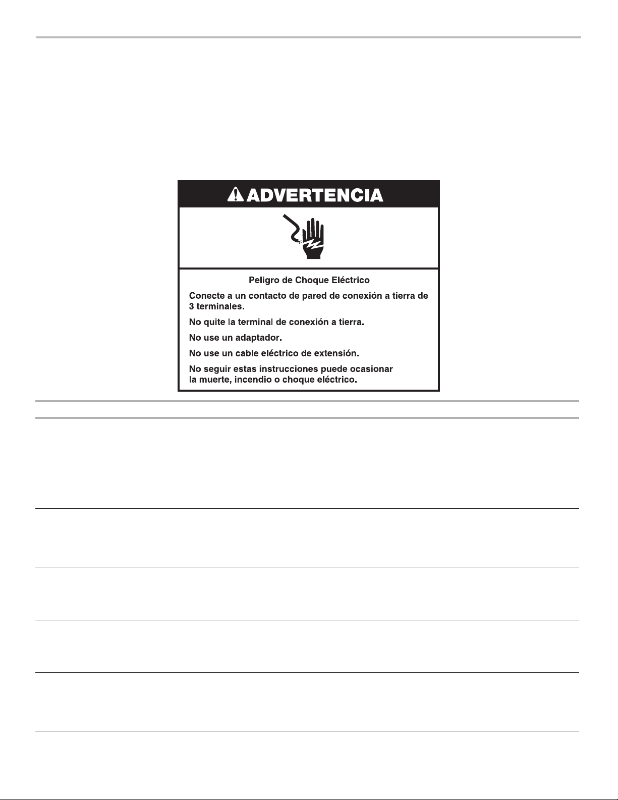
64
SOLUCIÓN DE PROBLEMAS
Pruebe primero las soluciones que aquí se recomiendan. Si necesita asistencia adicional o más recomendaciones que puedan ayudarle
a evitar una llamada de servicio técnico, consulte la página de la garantía de este manual y escanee el código con su dispositivo móvil
o visite producthelp.whirlpool.com. En Canadá, visite www.whirlpool.ca.
Contáctenos por correo con sus preguntas o dudas a la dirección que aparece a continuación:
En Estados Unidos:
Whirlpool Brand Home Appliances
Customer eXperience Center
553 Benson Road
Benton Harbor, MI 49022-2692
En Canadá:
Whirlpool Brand Home Appliances
Customer eXperience Centre
200 - 6750 Century Ave.
Mississauga, Ontario L5N 0B7
Incluya en su correspondencia un número de teléfono en el que se le pueda localizar durante el día.
Problema Posibles causas y/o soluciones
Nada funciona
El cable de suministro eléctrico está desenchufado. Enchufe el aparato a un tomacorriente de 3
terminales con conexión a tierra.
Se ha fundido un fusible de la casa o se ha disparado un cortacircuitos. Sustituya el fusible o rearme el
cortacircuitos. Si el problema continúa, llame a un electricista.
La válvula de cierre de gas principal o reguladora está en posición cerrada. Vea las Instrucciones de
instalación.
Se ha conectado incorrectamente la estufa al suministro de gas. Póngase en contacto con un
especialista en reparación competente o vea las Instrucciones de instalación.
Los quemadores
de superficie no
funcionan
La perilla del control no está fijada correctamente. Empuje hacia adentro la perilla antes de girar hasta
un ajuste.
Hay aire en las líneas de gas: Si esta es la primera vez que se usan los quemadores de superficie,
encienda cualquiera de las perillas de los quemadores de superficie para liberar el aire de las líneas de gas.
Orificios del quemador obstruidos Vea la sección “Quemadores de superficie sellados”.
Las llamas del
quemador de
superficie son
desparejas, amarillas
y/o hacen ruido
Orificios del quemador obstruidos Vea la sección “Quemadores de superficie sellados”.
Tapas del quemador colocadas incorrectamente: Vea la sección “Quemadores de superficie sellados”.
Estufa convertida incorrectamente: Si utiliza gas propano, llame al servicio técnico.
Hay demasiado calor
alrededor de los
utensilios de cocina
sobre la superficie de
cocción
El recipiente de cocción no coincide con la llama: El recipiente de cocción debe centrarse sobre el
quemador, con el fondo apoyado de forma nivelada en la rejilla. Deberá regularse la llama para que no se
eleve por los costados del recipiente.
Los resultados
de cocción de la
superficie de cocción
no son los esperados
Utensilio de cocina inadecuado: El utensilio de cocina ideal debe tener fondo plano, lados rectos, una
tapa que encaje bien y el material debe ser de un grosor mediano a pesado.
Se ha fijado la perilla de control en el nivel de calor incorrecto. Consulte la sección “Superficie de
cocción”.
La estufa no está nivelada: Nivele la estufa. Vea las Instrucciones de instalación.

65
Problema Posibles causas y/o soluciones
El horno no funciona
Hay aire en las líneas de gas: Si es la primera vez que se usa el horno, encienda la perilla de cualquiera de
los quemadores de superficie para liberar el aire de las líneas de gas.
El control está bloqueado: En la pantalla aparece “Control Lock”. Desplace hacia arriba para desbloquear.
La estufa está en modo Demo (modo de demostración): El modo de demostración desactiva todos los
elementos del horno. Consulte “Información” en la sección “Otros modos”.
Se ha fijado incorrectamente el control electrónico del horno: Consulte las secciones “Herramientas” y
“Otros modos”.
Las llamas del
quemador del horno
son amarillas o
ruidosas
Estufa convertida incorrectamente: Si utiliza gas propano, llame al servicio técnico.
La temperatura del
horno es demasiado
alta o demasiado
baja
La temperatura del horno debe regularse: Consulte “Temperatura” en la sección “Otros modos”.
No funciona el
ventilador de
convección
El ciclo de convección tiene lugar en los primeros 5 minutos de funcionamiento: Esto es normal. El
ventilador de convección comenzará a funcionar aproximadamente a los 5 minutos de comenzado el ciclo.
Está abierta la puerta del horno: Si se abre la puerta del horno durante la cocción por convección, el
ventilador se apagará de inmediato y se encenderá nuevamente cuando se cierre la puerta del horno.
La pantalla muestra
mensajes
Corte de corriente (aparece la hora destellando en la pantalla): Borre la pantalla. En algunos modelos,
vuelva a fijar el reloj, si es necesario. Consulte “Preferencias” en la sección “Otros modos”.
Código de error (la pantalla muestra una letra seguida de un número): Según el modelo, presione
CANCEL (Cancelar) para borrar la pantalla. Consulte las secciones “Herramientas” y “Otros modos”. Si
vuelve a aparecer, solicite servicio técnico.
La estufa está en modo Sabbath (de descanso) (pantalla muestra “Sabbath Mode”): Presione el botón
CANCEL (Cancelar) para salir del modo Sabbath.
El ciclo de limpieza
no actuó con todos
los derrames
Pasan demasiados ciclos de cocción entre los ciclos de limpieza o hay demasiadas salpicaduras
en las paredes y las puertas del horno: Ponga a funcionar ciclos de limpieza adicionales. Vea la sección
“Ciclo de limpieza” para obtener más información.
Quedan depósitos de
minerales en el piso
del horno después
del ciclo de limpieza
Se ha usado agua del grifo en el ciclo de limpieza: Use agua destilada o filtrada en el ciclo de limpieza.
Para quitar los depósitos, use un paño empapado con vinagre. Luego use un paño humedecido con agua
para quitar a fondo el resto de vinagre.
La estufa no está nivelada: Los depósitos de minerales se acumularán en las áreas secas del piso del
horno durante el ciclo de limpieza. Nivele la estufa. Vea las Instrucciones de instalación.
Para quitar los depósitos, use un paño empapado con vinagre. Luego use un paño humedecido con agua
para quitar a fondo el resto de vinagre.
Los resultados de
cocción del horno
no son los que se
esperaban
La estufa no está nivelada: Nivele la estufa. Vea las Instrucciones de instalación.
La temperatura fijada era incorrecta: Vuelva a verificar la receta en un libro de cocina confiable.
La temperatura del horno debe regularse: Consulte “Calibración de la temperatura” en la sección “Otros
modos”.
No se ha precalentado el horno: Consulte la sección “Cómo hornear y asar”.
Se han colocado las parrillas de modo inadecuado: Consulte la sección “Colocación de las parrillas y los
utensilios para hornear”.
No hay suficiente circulación de aire alrededor de los utensilios para hornear: Consulte la sección
“Colocación de las parrillas y los utensilios para hornear”.
Los alimentos tienen un dorado más oscuro causado por un utensilio de horneado de color mate u
oscuro: Baje la temperatura del horno 25°F (15°C) o mueva la parrilla a una posición más alta en el horno.
Los alimentos tienen un dorado más claro causado por un utensilio de cocción lustroso o de color
claro: Mueva la parrilla a una posición más baja en el horno.
Se ha distribuido el batido de manera despareja en el recipiente: Verifique que el batido esté nivelado
en la bandeja.
Se ha usado un tiempo de cocción incorrecto: Ajuste el tiempo de cocción.
No se ha cerrado la puerta del horno: Asegúrese de que el utensilio para hornear no impida que se cierre
la puerta.
Se ha abierto la puerta del horno durante la cocción: Al entreabrir el horno, se libera el calor y esto
puede dar como resultado tiempos de cocción más largos.
La parrilla está demasiado cerca del quemador para hornear, con lo que los artículos horneados
quedan demasiado dorados en la parte inferior: Sitúe la parrilla en una posición del horno más elevada.
Las cortezas de las tartas se doran con demasiada rapidez: Use papel de aluminio para cubrir el borde
de la tarta y/o reduzca la temperatura de horneado.

66
Ruidos
Problema Posibles causas y/o soluciones
El quemador de superficie hace ruidos
como estallidos
Quemador mojado: Déjelo secar.
Ruidos provenientes de la estufa a
gas durante el funcionamiento del
horneado y el asado a la parrilla
A continuación, se indican algunos
sonidos normales con las explicaciones.
Estos sonidos son ruidos normales del funcionamiento que se pueden escuchar
cada vez que se encienden los quemadores para hornear o asar durante el ciclo.
Estallido La válvula de gas se abre o se enciende y producirá un solo estallido cuando se
abra a presión del solenoide. El sonido es similar al de una ventosa que se separa
de una pieza de vidrio: Eso es normal.
Chasquido Los encendedores harán ruidos de chasquido varias veces hasta que se detecte la
llama. Esos son sonidos de chasquido breves, como cuando se dan golpecitos con
la uña sobre una pieza de vidrio: Eso es normal.
El relé del ventilador de convección se enciende y se apaga (en algunos modelos):
Eso es normal.
Zumbido o sonido de “puf”
Se está encendiendo el quemador de hornear o de asar a la parrilla: Esto es normal.
Las llamas del quemador del horno
son amarillas o ruidosas
Estufa convertida incorrectamente: Si utiliza gas propano, llame al servicio técnico.
ACCESORIOS
Para obtener accesorios en EE. UU., puede visitar nuestro sitio web en www.whirlpool.com. En Canadá, visite nuestro sitio web en
www.whirlpool.ca. Si tiene consultas o problemas, llame a Whirlpool Corporation Connected Appliances al número 1-866-333-4591.
Kit completo de limpieza para la
superficie de cocción
(modelos con vidrio de cerámica) (incluye
limpiador, protector, aplicador de protector,
raspador y estropajos)
Pida la pieza número 31605
Toallitas affresh
®
para limpiar acero
inoxidable
(modelos de acero inoxidable) Referencia
para pedido W10355049
Limpiador para superficies de
cocción affresh
®
(modelos con vidrio de cerámica)
Pida la pieza número W10355051
Almohadillas de limpieza para
superficies de cocción
(modelos con vidrio de cerámica)
Pida la pieza número W10391473
Limpiador affresh
®
para acero
inoxidable
(modelos de acero inoxidable)
Referencia para pedido W10355016
Limpiador affresh
®
para cocina y
electrodomésticos
Referencia para pedido W10355010
Kit de limpieza de hornos AquaLift
®
Pida la pieza número W10423113RP
Raspador para superficies de cocción
(modelos con vidrio de cerámica)
Pida la pieza número WA906B
Limpiador y pulidor de granito
Pida la pieza número W10275756
Juego para enlatado
(modelos con bobina)
Pida la pieza número 242905
Comal tipo gourmet
Pida la pieza número W10432544
Parrilla plana estándar para horno
Pida el número de pieza W10551060
Rejilla dividida para horno
Pida la pieza número 4396927
Parrilla de horno de máxima
capacidad
Pida la pieza número WPW10289145
Charola para asar y rejilla de
porcelana
Pida la pieza número 4396923
Parrilla para asar y bandeja para asar
a la parrilla de alta calidad
Referencia para pedido W10123240
Ensamble del borde
5/8" (17 mm), blanco: Pida la pieza número
W10675027
5/8" (17 mm), negro: Pida la pieza número
W10675026
5/8" (17 mm), acero inoxidable: Pida la
pieza número W10675028
1
1
/
8
" (2,9 cm), blanco: Pida la pieza
número W10731885
1
1
/
8
" (2,9 cm), negro: Pida la pieza número
W10731886
1
1
/
8
" (2,9 cm), acero inoxidable: Pida la
pieza número W10731887
Ensamble del zócalo
Blanco: Pida la pieza número W10655448
Negro: Pida la pieza número W10655449
Acero inoxidable: Pida la pieza número
W10655450
Kit de parrilla
Pida la pieza número W10432545
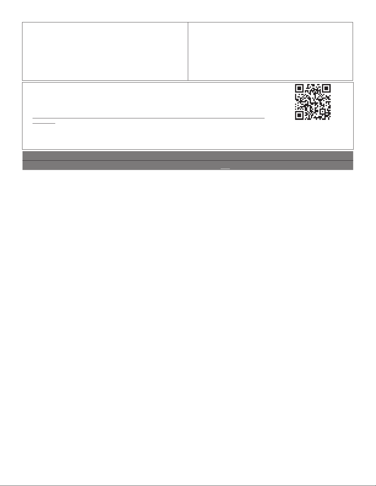
67
SI NECESITA SERVICIO TÉCNICO:
1. Antes de contactarnos para obtener servicio, determine si el producto requiere reparación. Algunas
consultas pueden atenderse sin servicio técnico. Tómese unos minutos para revisar la sección de Solución
de problemas o Problemas y soluciones del Manual de uso y cuidado, escanee el código QR que se
encuentra a la derecha para acceder a los recursos adicionales o visite www.whirlpool.com/product_help.
2. Todos los servicios bajo la garantía los brindan exclusivamente Prestadores autorizados de servicio de
Whirlpool. Para EE.UU. y Canadá, dirija todas las solicitudes de servicio bajo la garantía a:
Centro para la eXperiencia del cliente de Whirlpool
En EE.UU., llame al 1-800-253-1301. En Canadá, llame al 1-800-807-6777.
Si usted se encuentra fuera de los cincuenta Estados Unidos o Canadá, póngase en contacto con su distribuidor autorizado de Whirlpool para
determinar si corresponde otra garantía.
GARANTÍA LIMITADA DE
LOS ELECTRODOMÉSTICOS
PRINCIPALES DE
WHIRLPOOL
®
ADJUNTE SU RECIBO AQUÍ. SE REQUIERE LA PRUEBA DE COMPRA
PARA OBTENER SERVICIO BAJO LA GARANTÍA.
Tenga a mano la siguiente información cuando llame al Centro para la
eXperiencia del cliente:
■ Nombre, dirección y número de teléfono
■ Número de modelo y de serie
■ Una descripción clara y detallada del problema
■ Prueba de compra incluido el nombre y la dirección del distribuidor
o vendedor
GARANTÍA LIMITADA DE UN AÑO
LO QUE ESTÁ CUBIERTO LO QUE NO ESTÁ CUBIERTO
Durante un año a partir de la fecha
de compra, siempre y cuando este
electrodoméstico principal haya sido
instalado, mantenido y operado según las
instrucciones adjuntas o provistas con el
producto, Whirlpool Corporation o Whirlpool
Canada LP (en lo sucesivo denominado
“Whirlpool”) se hará cargo del costo de
las piezas especificadas de fábrica y del
trabajo de reparación para corregir defectos
en los materiales o en la mano de obra
existentes en el momento de la compra
de este electrodoméstico principal o, a su
sola discreción, reemplazará el producto.
En el caso de reemplazar el producto, su
electrodoméstico estará cubierto por la
garantía por el tiempo restante del período
de garantía de la unidad original.
SU ÚNICO Y EXCLUSIVO RECURSO
SEGÚN LOS TÉRMINOS DE ESTA
GARANTÍA LIMITADA SERÁ EL DE
REPARAR EL PRODUCTO SEGÚN SE
ESTIPULA EN LA PRESENTE. El servicio
deberá ser suministrado por una compañía
de servicio designada por Whirlpool. Esta
garantía limitada es válida solamente en
Estados Unidos o en Canadá y se aplica
solamente cuando el electrodoméstico
principal se use en el país en el que se ha
comprado. Esta garantía limitada entrará
en vigor a partir de la fecha de la compra
del consumidor original. Se requiere una
prueba de la fecha de compra original para
obtener servicio bajo esta garantía limitada.
1. Uso comercial, no residencial o familiar múltiple o uso diferente del indicado en las instrucciones
del usuario, del operador o de instalación publicadas.
2. Instrucción a domicilio sobre cómo usar el producto.
3. Servicio para corregir el mantenimiento o la instalación incorrecta del producto, la instalación
que no esté de acuerdo con los códigos eléctricos o de plomería o corrección de plomería o
instalación eléctrica doméstica (por ejemplo, instalación eléctrica, fusibles o mangueras de
entrada de agua del hogar).
4. Piezas de consumo (por ejemplo, focos de luz, baterías, filtros de agua o de aire, soluciones
de conservación, etc.).
5. Defectos o daños causados por el uso de piezas o accesorios no legítimos de Whirlpool.
6. Conversión del producto de gas natural o gas L.P.
7. Daño causado por accidente, uso indebido, abuso, incendio, inundación, actos fortuitos o el
empleo de productos no aprobados por Whirlpool.
8. Reparaciones a piezas o sistemas para corregir el daño o los defectos del producto a causa de
reparaciones por servicio no autorizado, alteraciones o modificaciones en el electrodoméstico.
9. Daños estéticos, incluyendo rayaduras, abolladuras, desportilladuras u otro daño al acabado del
electrodoméstico a menos que el mismo sea debido a defectos en los materiales o la mano de
obra y se le informe a Whirlpool en un lapso de 30 días.
10. Decoloración, herrumbre u oxidación de las superficies producto de entornos corrosivos o
cáusticos que incluyen, entre otras cosas, altas concentraciones de sal, humedad elevada o
exposición a productos químicos.
11. Pérdida de comida o medicamentos debido a la falla del producto.
12. Recogida o entrega. Este producto está destinado para ser reparado en su hogar.
13. Gastos de viaje o de transporte para prestar servicio en lugares remotos en los cuales no haya
disponible un técnico de servicio autorizado por Whirlpool.
14. Remoción o reinstalación de electrodomésticos en lugares inaccesibles o dispositivos
empotrados (por ejemplo, adornos, paneles decorativos, pisos, armarios, islas, mostradores,
paredes, etc.) que interfieran con el servicio, la remoción o el reemplazo del producto.
15. Servicio técnico o piezas para electrodomésticos con números de serie/modelo originales
removidos, alterados o no identificados con facilidad.
El costo de la reparación o del reemplazo bajo estas circunstancias excluidas correrá por
cuenta del cliente.
www.whirlpool.com/product_help

W11085353A 04/17
®
/™ ©2017 Whirlpool. Used under license in Canada. All rights reserved.
Utilisé sous licence au Canada. Tous droits réservés.
Usado en Canadá bajo licencia. Todos los derechos reservados