
INSTALLATION and SERVICE INSTRUCTIONS
USE and CARE INSTRUCTIONS
distributed by
DèLonghi
Pty Ltd
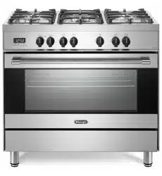
DE 906 GWF
DUAL FUEL COOKER

2
Dear Customer,
Thank you for having purchased and given your
preference to our product.
The safety precautions and recommendations reported
below are for your own safety and that of others. They
will also provide a means by which to make full use of
the features offered by your appliance.
Please keep this booklet in a safe place. It may be
useful in future, either to yourself or to others in the
event that doubts should arise relating to its operation.
This appliance must be used only for the task it has
explicitly been designed for, that is for cooking
foodstuffs. Any other form of usage is to be considered
as inappropriate and therefore dangerous.
The manufacturer declines all responsibility in the
event of damage caused by improper, incorrect or
illogical use of the appliance or be faulty installation.
PRODUCT LABEL
Important:
This appliance is designed and manufactured solely for the cooking of domestic
(household) food and is not suitable for any non domestic application and there-
fore should not be used in a commercial environment.
The appliance guarantee will be void if the appliance is used within a non domes-
tic environment i.e. a semi commercial, commercial or communal environment.

3
USING THE OVEN FOR THE FIRST TIME
You are advised to carry out the following operations:
■ Furnish the interior of the oven.
■ Switch the empty oven ON at maximum temperature for about two hours
to eliminate traces of grease and smell from the components.
■ Disconnect the appliance from the electric power supply and clean the
interior of the oven with a cloth soaked in water and neutral detergent
and dry thoroughly.
IMPORTANT PRECAUTIONS AND RECOMMENDATIONS FOR
USE OF ELECTRICAL APPLIANCES
Use of any electrical appliance implies the necessity to follow a series of fundamental
rules. In particular:
■ Never touch the appliance with wet hands or feet;
■ do not operate the appliance barefooted;
■ The appliance is not intended for use by young children or infirm persons
without supervision
■ Young children should be supervised to ensure they do not play with the
appliance
The manufacturer cannot be held responsible for any damages caused by improper,
incorrect or illogical use of the appliance.
This cooker has been designed and constructed in accordance with the following
codes and specifications:
AGA101 (AS 4551) Approval Requirements for Domestic Gas cooking appliances
AS/NZS 60335-1 General Requirements for Domestic electrical appliances
AS/NZS 60335-2-6 Particular Requirements for Domestic electrical cooking appliances
AS/NSZ 1044 Electromagnetic Compatibility Requirements.

4
IMPORTANT PRECAUTIONS AND RECOMMENDATIONS
After having unpacked the appliance, check to ensure that it is not damaged.
In case of doubt, do not use it and consult your supplier or a professionally qualified technician.
Packing elements (i.e. plastic bags, polystyrene foam, nails, packing straps, etc.) should not be left
around within easy reach of children, as these may cause serious injuries.
■ Do not attempt to modify the technical characteristics of the appliance as this may become dan-
gerous to use.
■ Do not carry out cleaning or maintenance operations on the appliance without having previ-
ously disconnected it from the electric power supply.
■ After use, ensure that the knobs are in the off position.
■
The appliance is not intended for use by young children or infirm persons unless they have been ade-
quately supervised by a responsible person to ensure that they can use the appliance safely.
■ During and after use of the appliance, certain parts will become very hot. Do not touch hot
parts. Care should be taken to avoid touching heating elements inside the oven.
■ Keep children away from the appliance when it is in use.
■ Young children should be supervised to ensure that they do not play with the appliance.
■ Some appliances are supplied with a protective film on steel and aluminium parts. This film must
be removed before using the appliance.
■ Make sure that electrical cables connecting other appliances in the proximity of the cooker can-
not come into contact with the hob or become entrapped in the oven door.
■ Do not line the oven walls with aluminium foil. Do not place baking trays or the drip tray on the
base of the oven chamber.
■ WARNING When correctly installed, your product meets all safety requirements laid down for
this type of product category. However special care should be taken around the rear or the
underneath of the appliance as these areas are not designed or intended to be touched and
may contain sharp or rough edges, that may cause injury.
■ Fire risk! Do not store flammable material in the oven and in the storage compartment.
■ Always use oven gloves when removing the shelves and food trays from the oven whilst hot.
■ Do not hang towels, dishcloths or other items on the appliance or its handle – as this could be a
fire hazard.
■ Clean the oven regularly and do not allow fat or oils to build up in the oven base or tray.
Remove spillages as soon as they occur.
■ Do not stand on the open oven door.
■ Always stand back from the appliance when opening the oven door to allow steam and hot air
to escape before removing the food.
■ This appliance is for domestic use only.
■ Safe food handling: leave food in the oven for as short a time as possible before and after cook-
ing. This is to avoid contamination by organisms which may cause food poisoning. Take particu-
lar care during warmer weather.
■ The manufacturer declines all liability for injury to persons or damage to property caused by
incorrect or improper use of the appliance.
■ WARNING: Taking care NOT to lift the oven by the door handle.
■ IMPORTANT NOTE: This appliance shall not be used as a space heater, espe-
cially if installed in marine craft or caravans.

5
INSTALLATION
CAUTION:
■ This appliance must be installed in accordance with these installation
instructions.
■ This appliance shall only be serviced by authorized personnel.
■ This appliance is to be installed only by an authorised person.
■ Incorrect installation, for which the manufacturer accepts no responsibility,
may cause personal injury of damage.
■ Always disconnect the cooker from mains power supply before carrying out
any maintenance operations or repairs.
■ In the room where the cooker is installed, there must be enough air to
allow the gas to burn correctly, according to the current local regulations.
ELECTRICAL REQUIREMENTS
■ The appliance must be connected to the mains checking that the voltage corre-
sponds to the value given in the rating plate and that the electrical cable sec-
tions can withstand the load specified on the plate.
■ The plug must be connected to an earthed socket in compliance with safety
standards.
■ If the appliance is supplied without plug, fit a standard plug which is suitable for
the power consumed by the appliance.
■ The appliance must be connected directly to the mains placing a two pole
switch with minimum opening between the contacts of 3 mm between the
appliance and the mains.
■ The power supply cable must not touch the hot parts and must be positioned so
that it does not exceed 50°C above ambient.
■ Once the appliance has been installed, the switch or socket must always be
accessible.
■
If the supply cord is damaged it must be replaced by the manufacturer or
it’s Service Agent or a similarly qualified person in order to avoid a hazard.
WARNING: This cooker must be connected to electrical supply using
V105 insulated cable.
N.B. The connection of the appliance to earth is mandatory.
If the installation requires alterations to the domestic electrical system call a qualified
electrician.
He should also check that the socket cable section is suitable for the power drawn by
the appliance.
Appliance power rating:
230 V~ 3345 W (14.5 A)
240 V~ 3640 W (15.1 A)
Replacing the power cord must be done by a qualified electrician in accor-
dance with the instructions supplied by the manufacturer and in compliance
with established electrical regulations.

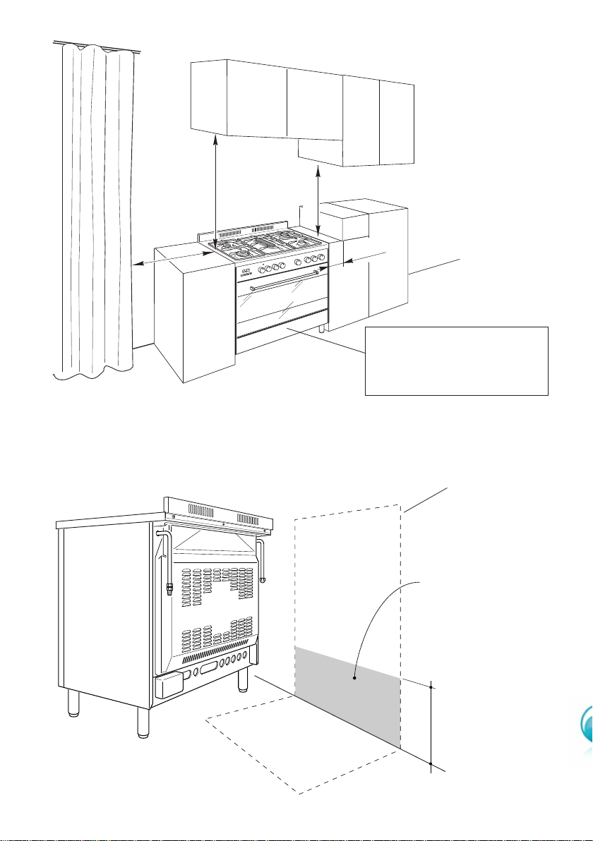
CLEARANCES
Installation clearances and protection of combustible surfaces shall comply with the
current local regulations eg. AG 601 (AS 5601) Gas Installations code.
Installation shall comply with the dimension in Fig. 1a bearing in mind that.
Overhead Clearances
In no case shall the clearances between the highest part of the cooker be less than
600 mm or for an overhead exhaust fan 750 mm. AII other downward facing com-
bustible surfaces less than 600 mm above the cooker surface shall be protected for the
full width of the cooking surface in accordance with the standards noted above. In no
case shall the clearance be less than 450 mm.
Rear and Side Clearances
Where the dimensions from the periphery of the nearest burner to any vertical com-
bustible surface is less than 200 mm the surface shall be protected in accordance with
the standards to a height of not less than 150 mm above the cooking surface for the
full width or depth of the cooking surface.
Where the dimensions from the periphery of the nearest burner to any horizontal com-
bustible surface is less than 200 mm, the horizontal surface shall be greater than
10 mm below the surface of the hob, or the horizontal surface requirement above.
Protection of combustible surfaces.
The standards above specify that where required protection shall ensure that the sur-
face temperature of the combustible surface does not exceed 65°C above room tem-
perature.
If the cooker is located on a pedestal it is necessary to provide safety mea-
sures to prevent falling out.
6
7
750 mm
500 mm
50 mm
A
U
T
O
450 mm
Cooker overall dimensions [mm]
• height: min 900 - max 925
• width: 900
• depth: 600
Figure 1a
max 290 mm
Dotted line
showing the
position of the
cooker when
installed
Area for GAS
and ELECTRIC
connection
GAS AND ELECTRIC CONNECTION
Figure 1b
8
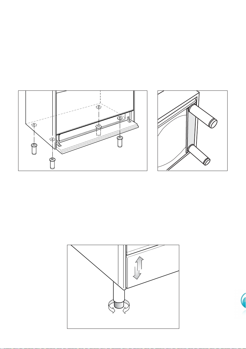
LEVELLING THE COOKER
The cooker may be levelled by screwing the lower ends of the feet IN or OUT (fig. 4).
Figure 4
Figure 2
FITTING THE ADJUSTABLE FEET
The adjustable feet must be fitted to the base of the cooker before use.
Rest the rear of the cooker an a piece of the polystyrene packaging exposing the
base for the fitting of the feet.
Fit the 4 legs by screwing them tight into the support base as shown in figure 3.
Figure 3
9
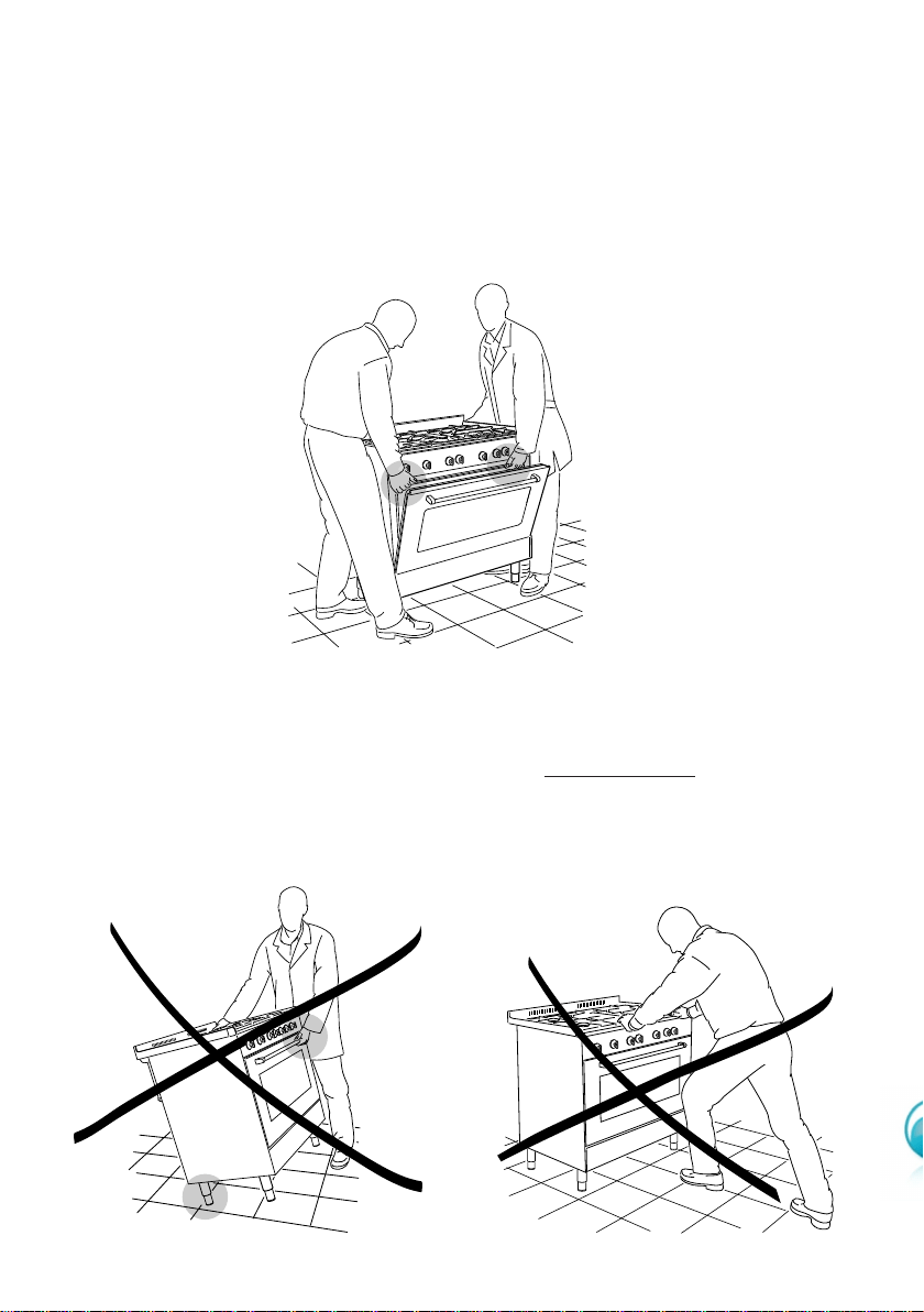
WARNING
When moving cooker to its final posi-
tion DO
NOT DRAG (fig. 7).
Lift feet clear of floor (fig. 5).
Figure 6 Figure 7
Figure 5
WARNING
When raising cooker to upright position always ensure two people carry out
this manoeuvre to prevent damage to the adjustable feet (fig. 5).
MOVING THE COOKER
WARNING
Be carefull: do not lift the cooker
by the door handle when raising
to the upright position (fig. 6).
10
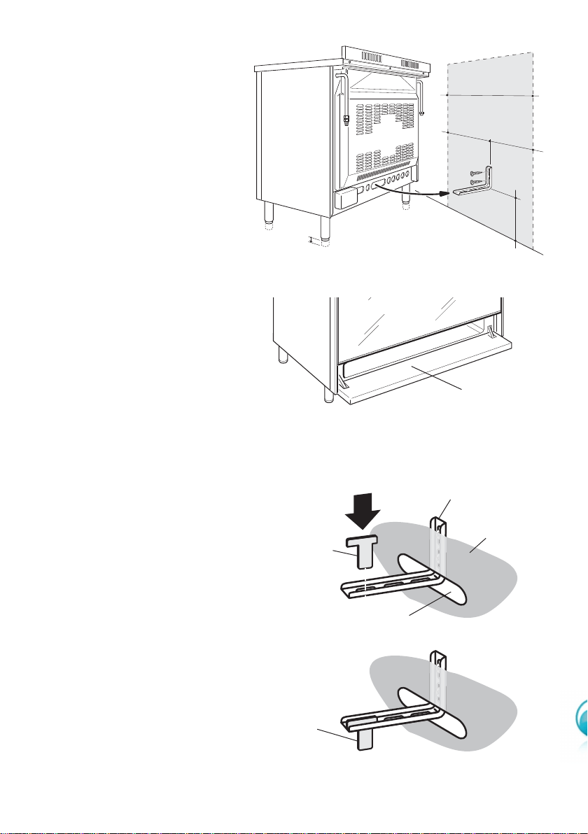
ANTI-TILT BRACKET
Important!
To restrain the appliance and
prevent it tipping accidentally,
fit a bracket to its rear to fix it
securely to the wall. Make sure
you also fit the supplied lock
pin to the anti-tilt bracket.
To fit the anti-tilt bracket:
1. After you have located where
the cooker is to be positioned,
mark on the wall the place
where the two screws of the
anti-tilt bracket have to be fitted.
Please follow the indications
given in Fig. 8a.
2. Drill two 8 mm diameter holes
in the wall and insert the plastic
plugs supplied.
Important!
Before drilling the holes,
check that you will not dam-
age any pipes or electrical
wires.
3. Loosely attach the anti-tilt brack-
et with the two screws supplied.
4. Move the cooker to the wall and
adjust the height of the anti-tilt
bracket so that it can engage in
the slot on the cooker’s back, as
shown in Fig. 8a.
5. Tighten the screws attaching the
anti-tilt bracket.
6. Push the cooker against the wall
so that the anti-tilt bracket is fully
inserted in the slot on the cook-
er’s back.
7. Access the bracket and fit the
lock pin:
• Open the pivoting panel (Fig.
8b).
• Fit the lock pin through the
bracket, as shown (Fig. 8c).
• Close the pivoting panel.
min 220
max 245
450
450
0
+ 25
900 mm
1
2
Figure 8b
Opening the pivoting panel
Figure 8c
Fitting the lock pin through
the bracket
Pivoting
panel
Figure 8a
Fitting the anti-tilt bracket
Lock pin
correctly
fitted
Lock pin
Slot on the
cooker’s back
Cooker’s
back
Anti-tilt bracket
attached on the
rear wall
11
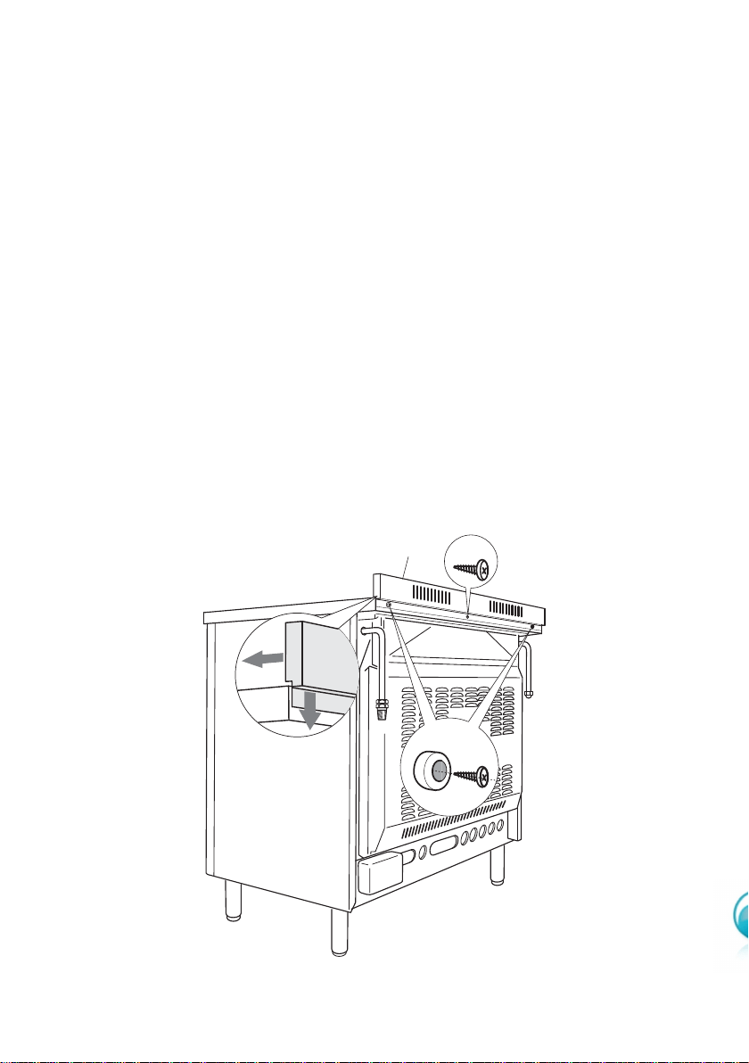
Figure 9
A
C
B
BACKGUARD
Before installing the cooker, assemble the backguard C (fig. 9).
■ The backguard C can be found packed at the rear of the cooker.
■ Before assembling remove any protective film/adhesive tape.
■ Remove the two spacers A and the screw B from the rear of the cooktop.
■ Assemble the backguard as shown in figure 9 and fix it by screwing the central
screw B and the spacers A.
C
B
A
12
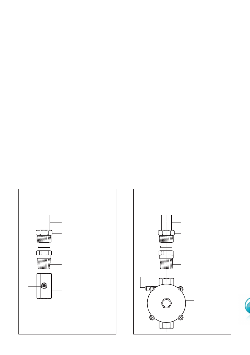
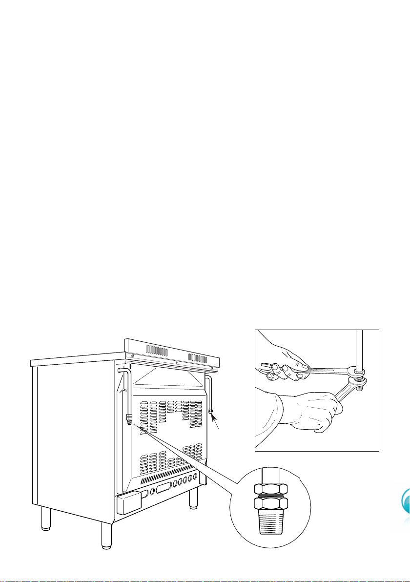
GAS SUPPLY:
■ The connection must be executed by an authorised person according to the rele-
vant standards.
■ Before connecting the appliance to the gas main, mount the brass conical adaptor
onto the gas inlet pipe, upon which the gasket has been placed (figures 10-11).
Conical adaptor and gasket are supplied with the appliance (packed with conver-
sion kit for use with Natural gas or ULPG).
■ This appliance is suitable for use with Natural Gas or ULPG. (Check the “gas type”
sticker attached to the appliance).
■ For Natural Gas models the gas supply is connected to the pressure regulator
which is supplied with the appliance (fig. 11). Adjust the regulator to obtain a test
point pressure of 1 kPa with the two semi-rapid (SR) burners operating at the maxi-
mum.
■ For ULPG models the gas supply is connected to the test point adaptor which is
supplied with the appliance (fig. 10) and ensure that the supply pressure is regulat-
ed to 2.75 kPa.
■ The connection must be made at the rear of appliance (left or right); the pipe do
not cross the cooker.
■ The inlet not used must be closed off with the cap and sealing gasket supplied.
■ IMPORTANT: Use two spanners to tighten or loosen the connecting pipe (fig. 13)
Gas connection for
ULPG
Figure 11
Figure 10
Gas connection for
NATURAL GAS
Gas inlet pipe
Nipple
Gasket
Brass conical adaptor
(Thread tight: use
suitable seal)
Gas inlet pipe
Nipple
Gasket
Brass conical adaptor
(Thread tight: use
suitable seal)
Gas regulator
Test point adaptor
Test
point
Test
point
13
1. After connecting the gas supply, check the piping and connections for leaks using
a soap and water solution. The presence of bubbles indicates a leak, tighten or
replace connections as appropriate.
Warning: Do not use any naked flame to check for leaks.
2. Adjust the test point pressure or supply pressure to the value which is appropriate
for the gas type.
3. The operation of the appliance must be tested when installation is completed.
4. Turn on the appliance gas controls and light each burner individually and in combi-
nation. Check for a well defined blue flame without any yellow tipping. If any
abnormality is evident then check that the burner cap is located properly and the
injector nipple is aligned correctly.
5. Check the minimum burner setting by quickly rotating the gas control knob from
the maximum to the minimum position, the flame must not go out. If adjustment is
required carry out the “minimum burner setting adjustment" procedure described
6. If satisfacfory performance cannot be obtained, the installer shall check the installa-
tion and notify the local gas supply authority for a gas supply problem, or if it is an
appliance problem, our Customer Service Centre should be called to obtain the
nearest authorized Delonghi Service Agent.
WARNING, This appliance IS NOT SUITABLE for installation with a hose
assembly.
Plug
Figure 12 Figure 13
14
CONVERSION PROCEDURE (to convert to Natural gas or to ULPG)
REPLACING THE INJECTORS
This appliance is suitable for use with Natural gas or ULPG (check the “gas type” sticker
attached to the appliance). A label stating the type of gas used after replacing the
injectors must be attached at the rear of the appliance, in proximity of the gas inlet
connection. The nominal gas consumption and injector size details are provided in
table at page 16.
To replace the injectors proceed as follows:
■ Remove pan supports and burners from the cooktop.
■ Using a spanner, remove the injector J (figs. 14a, 14b) and replace it with one
according to the gas type (see following tables - page 16).
■ Affix to the rear of the appliance, in proximity of the gas inlet connections, the
warning label (supplied with the conversion kit) stating that the cooker has
been converted for use with ULPG / Natural gas.
IMPORTANT
■ If the cooker is suitable for use with Natural gas and must be converted for use
with ULPG, before connecting to gas main remove the appliance gas regulator
and replace with test point adaptor (see figs. 10-11)
■ If the cooker is suitable for use with ULPG and must be converted for use with
Natural gas, before connecting to the gas main remove the appliance test point
adaptor and replace with gas regulator (see figs. 10-11).
NOTE:
Gas regulator and test point adaptor are supplied with the appliance (packed with
conversion kit)
The burners are designed so that regulation of primary air is not required.
Figure 14a
J
Figure 14b
J
15
MINIMUM BURNER SETTING ADJUSTMENT
Check whether the flame spreads to all burner ports when the burner is lit with the gas
tap set to the minimum position. If some ports do not light, increase the minimum gas
rate setting.
Check whether the burner remains lit even when the gas tap is turned quickly from
the maximum to the minimum position. If the burner does not remain lit, increase the
minimum gas rate setting.
The procedure for adjusting the minimum gas rate setting is described below.
■ Turn on the burner
■ Turn the tap to the MINIMUM position
■ Take off the knob
■ With a small flat screwdriver turn the screw “F” (fig. 15) to the correct regulation.
Normally for ULPG, the regulation screw is tightened up.
Figure 15
F
16
LUBRICATION OF THE GAS TAPS
If the gas tap becomes stiff, it is necessary to dismantle it carefully and clean it with
petroleum spirit. Specialist high temperature resistant grease should be used to
lubricate the tap before replacing.
The operations must be carried out by an authorised person/service agent.
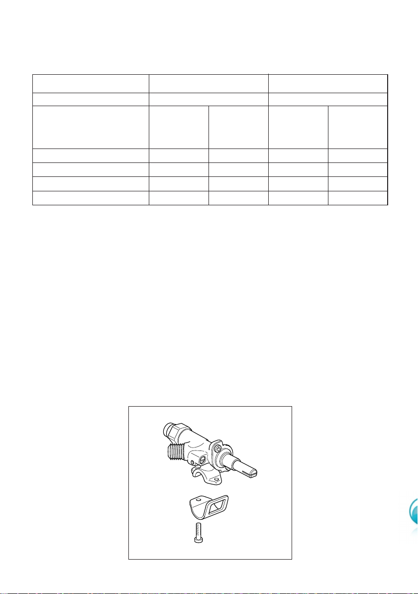
TABLE FOR THE CHOICE OF THE INJECTORS
Natural gas ULPG
Test Point Pressure [kPa] 1.0 2.75
BURNER
Auxiliary (A) 0.85 3.60 0.53 3.60
Semi-rapid (SR) 1.12 6.30 0.70 6.30
Triple ring (TC) 1.65
13.30
0.95 11.90
Fish burner (FB) 1.45
10.60
0.91 10.60
Gas
Consumption
[MJ/h]
Injector
Orifice Dia.
[mm]
Gas
Consumption
[MJ/h]
Injector
Orifice Dia.
[mm]
Figure 16
17
USE and CARE
CAUTION:
■ This appliance must be used only for the task it has explicitly been designed for,
that is for domestic cooking of foodstuffs. Any other form of usage is to be con-
sidered as inappropriate and therefore dangerous.
■ Do NOT place combustible materials or products on this appliance at any time.
■ Do NOT spray aerosols in the vicinity of this appliance while it is in use.
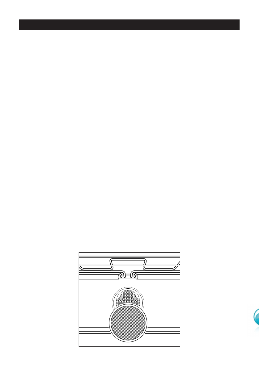
GREASE FILTER
■ A special screen is provided at the back of the multifunction oven to catch
grease particles, mainly when meat is being roasted (fig. 17).
■ When baking pastry etc. this filter should be removed.
■ Always clean the filter after cooking as any solid residues on it might adversely
affect the oven performance.
Figure 17
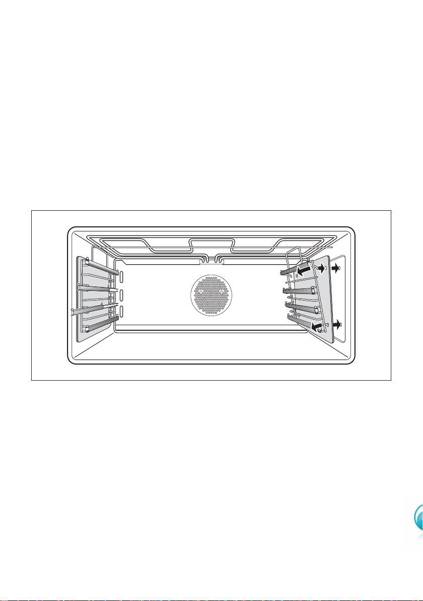
SLIDING SHELVES
■ They facilitate the insertion and removal shelves during cooking. These shelves
support all accessories and the dishwarmer safe.
■ The shelves block when pulled to the maximum position.
■ The sliding shelves can be removed easily by lifting slightly and detaching them
from the oven walls.
18
Figure 18
USING THE OVEN FOR THE FIRST TIME
■ Slide off the sliding shelves and the catalytic liners to the oven wall as in Fig. 18.
■ Clean the inside of the oven with a cloth soaked in water and neutral detergent
and dry thoroughly.
■ Slide in the catalytic liners and sliding shelves on the oven wall as in Fig. 18.
■ Slide in the grease filter on the back of the oven as in Fig. 17.
19
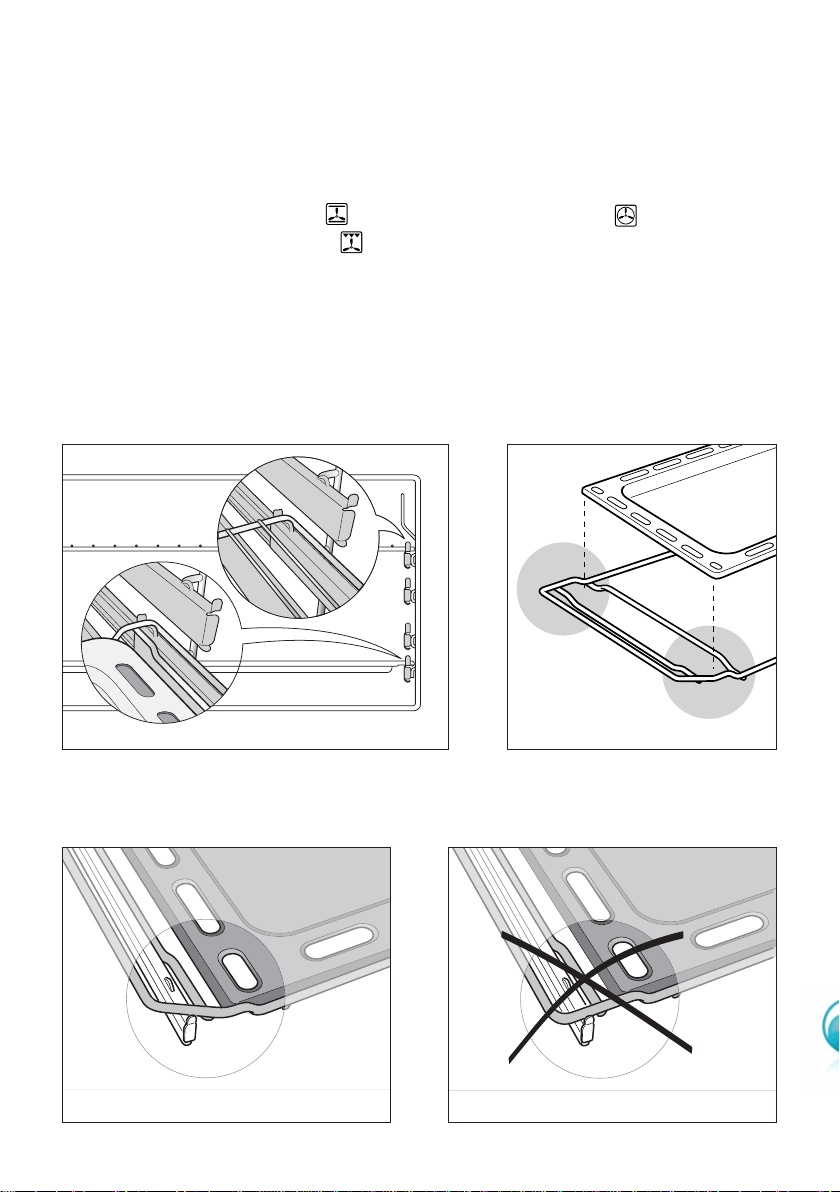
■ Position the shelf as per Fig. 19.
■ Position the oven tray on its wire shelf (fig. 20).
Important: The oven tray wire shelf must be correctly inserted in the oven as
per Figures 20, 21 and 22.
■ To eliminate traces of grease in manufacture it is necessary to pre-heat the oven
at the maximum temperature.
• For 60 minutes in the position, for 30 minutes in the position and for
another 15 minutes in the position.
WARNING: The door is hot, use the handle.
Figure 19
Figure 20
Figure 21 Figure 22
WRONGCORRECT
FRONT
FRONT
FRONT
REAR
20
Figure 23
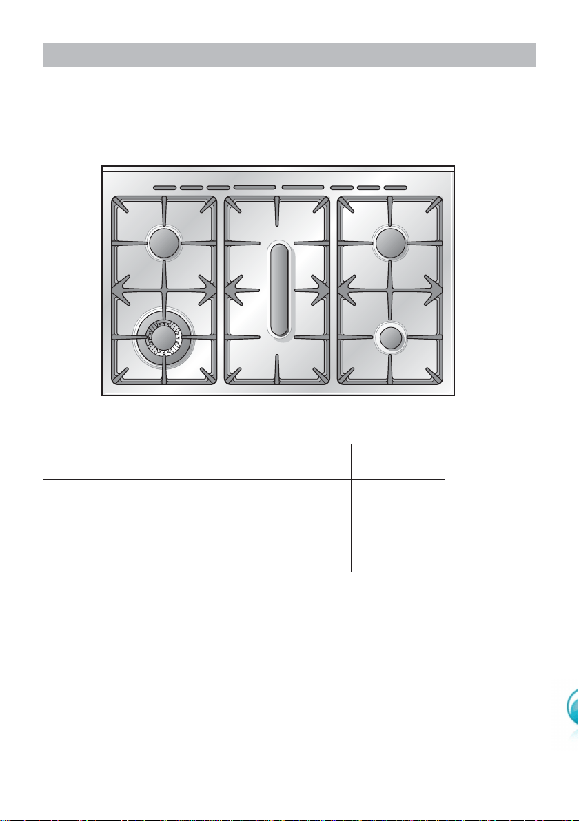
GAS HOB
2
3
2
1
4
GAS BURNERS Natural Gas ULPG
MJ/h MJ/h
1. Auxiliary burner (A) 3.6 3.6
2. Semi-rapid burner (SR) 6.3 6.3
3. Fish burner (FB) 10.6 10.6
4. Triple ring burner (TC) 13.3 11.9
21
Figure 24
LIGHTING GAS BURNERS
FITTED WITH SAFETY VALVE DEVICE AND ELECTRONIC IGNITION
■ Check that the electricity is
switched on to allow spark igni-
tion.
■ Make sure that all controls are
turned to zero.
■ The gas flow to the burners is
controlled by taps with a safety
cutout device. If the burner
flame should go out, the safety
cut-off valve will automatically
stop the gas flow. The switch for
the electric ignition is incorporat-
ed in the knobs.
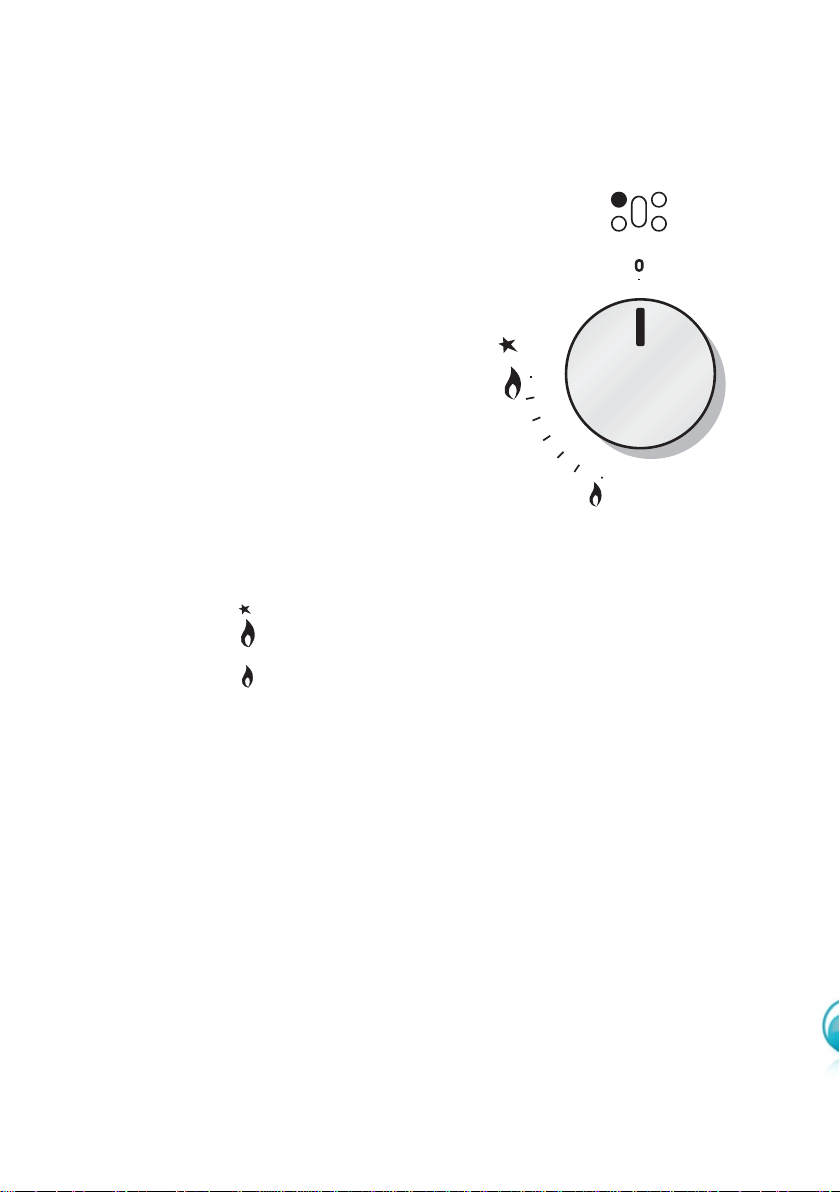
■ You control the flow by turning the knob indicator to line up with the following
symbols:
– Symbol ● : tap closed
(burner off)
– Symbol : High (maximum)
– Symbol : Low (minimum)
■ To ignite automatically, push the required knob down and turn it to maximum,
keeping the knob down until the burner lights. When the flame is lit, wait for
about ten second with the knob down (safety cut-off activation delay).
■ You can control the temperature by the knob to “High” (maximum) from “Low”
(minimum).
■ To switch off, turn the knob clockwise until you hear the safety click.
■ Note that, if you are using a burner at the minimum setting, you turn the knob
clockwise past the maximum setting before reaching the off position.
■ Whenever the lighting of the burners is difficult due to peculiar conditions of
the gas features or supply, it is advised to repeat the ignition with the knob on
“minimum” position.
■ If when lighting any of the burners an abnormal flame appears, switch the
burner off and relight using the minimum setting.
■ If the flame is still not correct, turn the burner off and call our Customer Service
center for your nearest Authorized Delonghi Service Agent.
■ In the case of a mains failure light the burner with a match or lighted taper.
22
CHOICE OF BURNER
Burners Pan diameter
Auxiliary
*
12 - 14 cm
Semi-rapid 16 - 24 cm
Triple ring 26 - 28 cm
Fish-burner from 12x30 to 18x40 cm
Wok max 36 cm
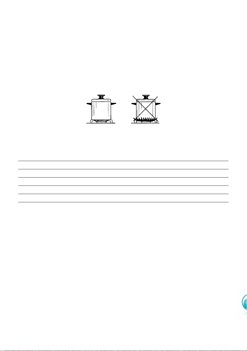
The burner must be chosen according to the diameter of the pans and energy
required.
For optimum efficiency uso a wok or pan no smaller than 230mm diameter.
Saucepans with handles which are excessively heavy, in relationship to the weight
of the pan, are safer as they are less likely to tip.
Pans which are positioned centrally on burners are more stable than those which
are offset.
It is far safer to position the pan handles in such a way that they cannot be
accidentally knocked.
When deep fat frying fill the pan only one third full of oil.
DO NOT cover the pan with a lid and DO NOT leave the pan unattended.
In the unfortunate event of a fire, leave the pan where it is and turn off all
controls.
Place a damp cloth or correct fitting lid over the pan to smother the flames.
DO NOT use water on the fire.
Leave the pan to cool for at least 30 minutes.
Figure 25
do not use pans with concave or convex bases
(
*
) with grill for small cookware: minimum diameter 6 cm.
23
Figure 26a Figure 26b
Figure 27
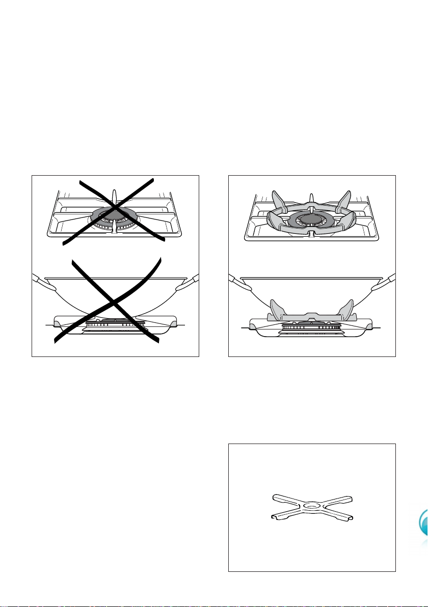
CORRECT USE OF TRIPLE-RING BURNER
■ The flat-bottomed pans are to be placed directly onto the pan-support.
■ To use the WOK, you must place the wok stand in the CORRECT position as
shown in Fig. 26a-26b.
IMPORTANT:
The special grille for wok pans (fig. 26b) MUST BE PLACED ONLY over the pan-rest for
the triple-ring burner.
WRONG
CORRECT
GRATE FOR SMALL PANS
(fig. 27)
This grate is to be placed on top of the
(smaller) auxiliary burner when using
small diameter pans, in order to prevent
them from tipping over.
24
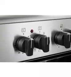
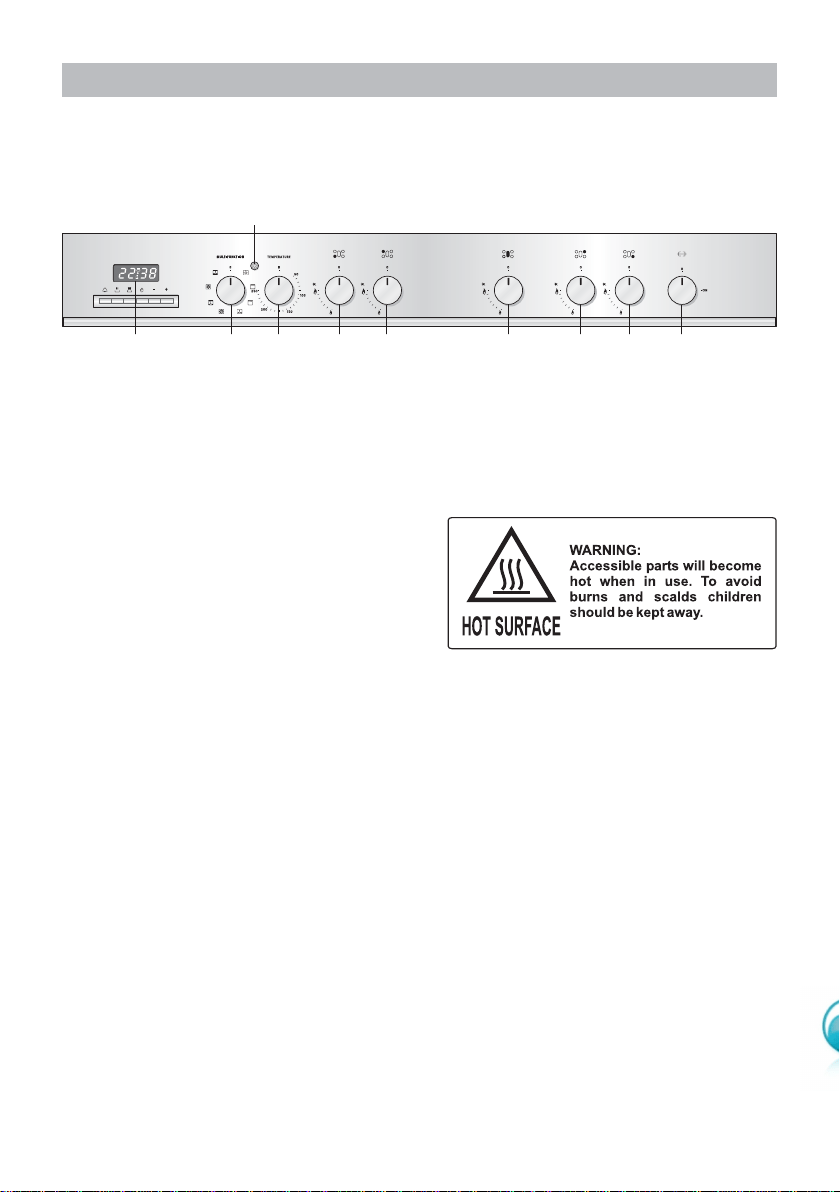
CONTROL PANEL - Controls description
1. Oven switch knob
2. Oven thermostat knob
3. Front left burner control knob
4. Rear left burner control knob
5. Fish burner control knob
6. Rear right burner control knob
7. Front right burner control knob
8. Rotisserie control knob
9. Electronic programmer
Pilot lamp:
10. Oven thermostat indicator light
Figure 28
A
U
T
O
P
91234 5678
MULTIFUNCTION OVEN
10
Please note: This appliance incorporates a safety cooling fan which you will hear
operating whenever the oven or grill are in use. This fan is to reduce the external
temperature of the appliance and cool the internal components.

25
OPERATING PRINCIPLES
Heating and cooking in the MULTI-FUNCTION oven are obtained in the following
ways:
a. by normal convection
The heat is produced by the upper and lower heating elements.
b. by forced convection
The fan draws in air contained within the oven housing at the rear of the oven and
forces it over the circular heating element. The hot air envelops the food in the oven
givin faster and more even cooking before it is drawn back into the housing to
repeat the cycle. It is possible to cook several dishes simultaneously due to the even
distribution of heat within the oven.
c. by forced semi-convection
The heat produced by the top and bottom heating elements is distributed through-
out the oven by the fan.
d. by radiant heat
The food is grilled by the infra red grill element.
e. by radiant heat and ventilation
The food is grilled by the grill element is distributed throughout the oven
f. by ventilation
The food is defrosted by using the fan only function without heat.
WARNING:
The door is hot, use the handle.
During use the appliance becomes hot. Care should be taken to avoid touching
heating elements inside the oven.
GENERAL FEATURES
With your new Multi-Function oven it is possible to cook a variety of food using the 6
different cooking functions.
These 6 functions are obtained using a combination of the 4 different heating elements
plus a defrost function using the fan only.
26
Figure 29
TRADITIONAL CONVECTION COOKING
The upper and lower heating elements come on. The heat being dispersed by natural
convection. The temperature range must be set between 50 °C and 250 °C using the
thermostat.
The oven must be preheated before cooking.
Ideal for:
Food that requires the same degree of cooking both inside and out, for example
roasts, spare pork ribs, meringues etc.
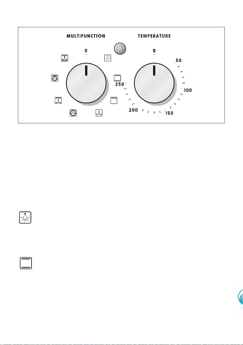
FUNCTION SELECTOR KNOB
Rotate the knob clockwise to set the oven for one of the following functions.
OVEN LIGHT
By setting the knob to this position, only the oven light comes on.
It remains on in all the cooking modes.
THERMOSTAT KNOB
This only sets the cooking temperature and does not switch the oven on.
Rotate clockwise until the required temperature is reached (from 50 °C to 250 °C).
27
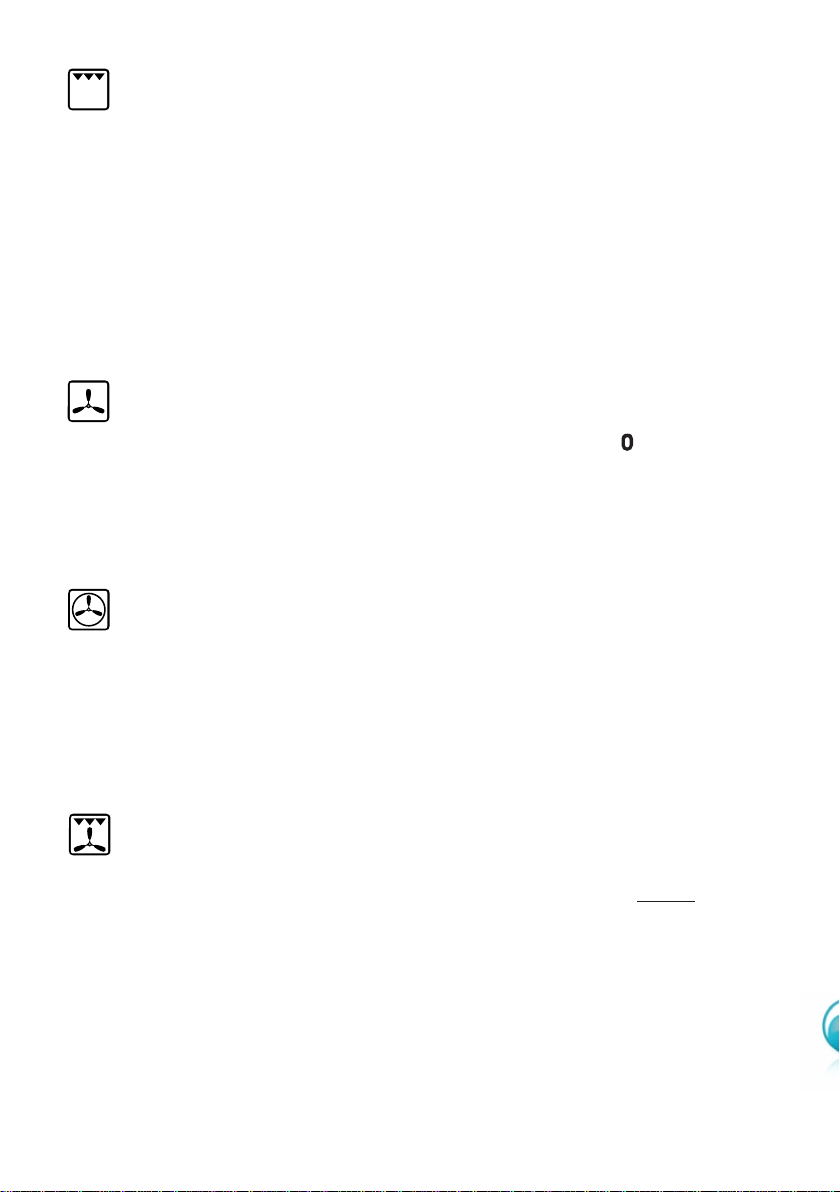
DEFROST
Only the oven fan comes on. Use with the thermostat knob set to “ ” - other temper-
ature have no effect. The food is thawed by ventilation without heating.
Ideal for:
Quick thawing of frozen foods; one kg requires approximately 1 hour.
Thawing times vary according to the quantity and type of food to be thawed.
GRILLING
The infrared grill element at the top of the oven comes on. The heat is dispersed by
radiation.
Use with the oven door closed and the thermostat knob to position 225 °C for max
15 minutes, then to position 175 °C.
For cooking hints, see the chapter “USE OF THE GRILL”.
Ideal for:
Intense grilling, browning, cooking au gratin and toasting etc.
It is recommended that you do not grill for longer than 30 minutes at any
one time. Attention: the oven door becomes very hot during operation.
Keep children away.
FAN GRILL
Both the grill and the fan come on. Most of the cooking is done by grilling and then
the hot air circulated around the oven. The oven door should be kept closed
.
The temperature can be set between 50 °C and 200 °C max.
The oven should be preheated for 5 minutes before cooking. For further cooking hints
see “GRILLING AND COOKING AU GRATIN”.
Ideal for:
Quick sealing in of food juices for example such as hamburger, chicken pieces, chops.
It is recommended that you do not grill for longer than 30 minutes at any
one time.
Attention: the oven door becomes very hot during operation.
Keep children away.
FAN FORCED
The circular element and fan come on. The heat is dispersed by forced convection and
the temperature can be varied to between 50 °C and 250 °C via the thermostat knob.
The oven does not require preheating.
Ideal for:
Food which has to be well-cooked outside and soft or rosy inside, for example
lasagne, lamb, roast beef, whole fish etc.

28
MAINTAINING TEMPERATURE AFTER COOKING OR
SLOWLY HEATING FOODS
The upper element, the circular element and the fan come on.
The heat is circulated by forced convection with greater intensity in the upper part.
The temperature can be set to between 50 °C and 140 °C via the thermostat knob.
Ideal for:
Keeping food warm after any type of cooking. Slow heating of cooked food.
MULTI-FUNCTION
The upper and lower heating elements come on and the fan come on - the heat from
the element being circulated by the fan.
The temperature range can be set to between 50 °C and 250 °C using the thermostat.
Ideal for:
Large bulky quantities of food that require even cooking throughout for example large
roasts, turkey, roast turkey, cakes etc.
COOKING ADVICE
Remember to keep children away from the appliance when you use the grill or oven, since
these parts become very hot.
STERILIZATION
Sterilization of foods to be preserved, in full and hermetically sealed jars, is done in the
following way:
a. Set the switch to position .
b. Set the thermostat knob to position 185 °C and preheat the oven.
c. Fill the dripping pan with hot water.
d. Set the jars onto the dripping pan making sure they do not touch each other and
the door and set the thermostat knob to position 135 °C.
When sterilization has begun, that is, when the contents of the jars start to bubble,
turn off the oven and let cool.
Check your recycle book for full instructions.

29
GRILLING AND COOKING AU GRATIN
As the hot air completely covers the food to be cooked, grilling may be done with
the food on rack in the oven. The knob should be switched to position .
The thermostat should be set to 200 °C and the oven pre-heated.
The food should be placed on a rack in the oven for the required cooking time.
Adding a few dabs of butter before the end of the cooking time gives the golden “au
gratin” effect.
It is recommended that you do not grill for longer than 30 minutes at any
one time.
USE OF THE GRILL
Preheat the oven for about 5 minutes with the door closed.
Introduce the food to be cooked, positioning the rack as close to the grill as possible.
The dripping pan should be placed under the rack to catch the cooking juices and
fats.
Do not grill for longer than 30 minutes at any one time.
SIMULTANEOUS COOKING OF DIFFERENT FOODS
The oven set on position can cook several different foods together. Foods as
diverse as fish and cakes can be cooked together without the cross transference of
flavours. This is because the fats and cooking smell that would normally be
deposited on the different foods are oxidised and are not absorbed by the foods.
The cooking temperature of the foods, however must be within 20 °C-25 °C of
each other. The food with the longest cooking time will be put into the oven first
and the other foods are added as necessary according to their cooking times.
ROASTING
To obtain classical roasting, it is necessary to remember:
■ that it is advisable to maintain a temperature between 180 °C and 200 °C.
■ that the cooking time depends on the quantity and the type of foods.
WARNING: Accessible parts may become hot when the grill is used.
Children should be kept away.
30
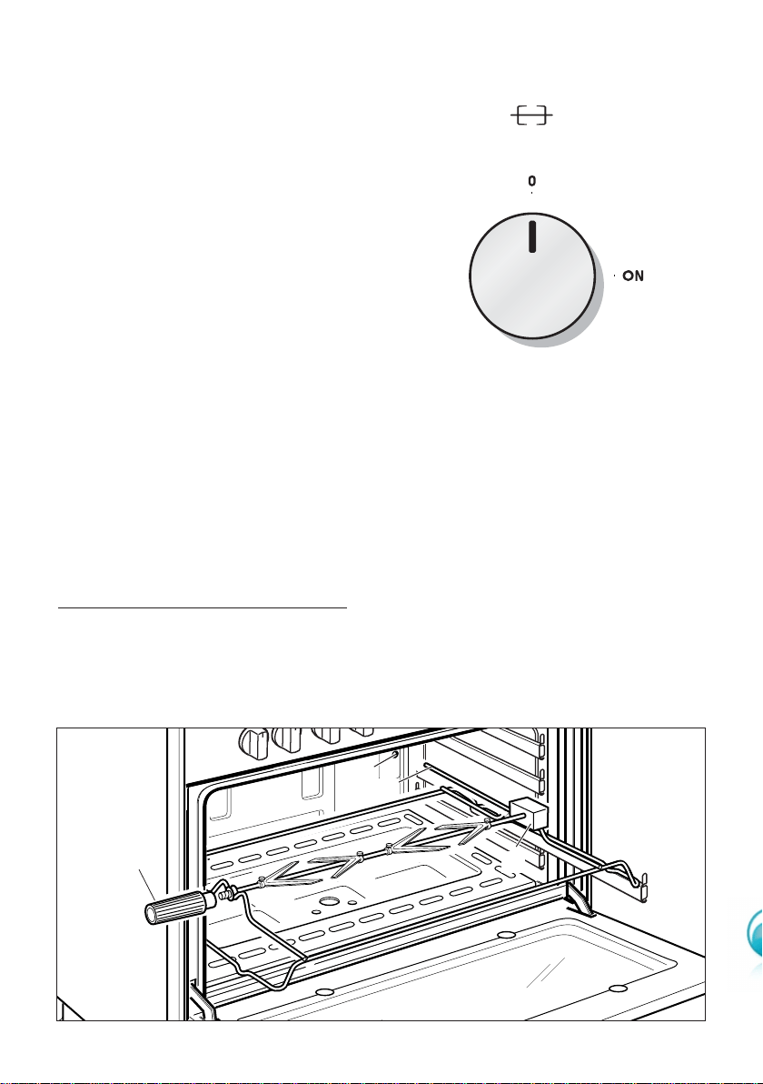
ROTISSERIE (Fig. 31)
This is used for spit roasting under the
grill and comprises:
■ an electric motor fitted to the rear
of the oven
■ a stainless steel skewer provided
with slide-out heatless handgrip
and two sets of adjustable forks
■ a skewer support to be fitted in
the middle runner.
The rotisserie motor is operated by a
switch (Fig. 30).
Figure 30
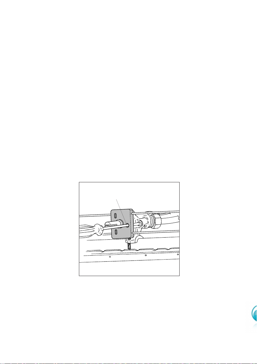
USE OF THE ROTISSERIE
■ Insert the tray into the lowest rack holders of the oven and insert the rod sup-
port into the intermediate rack holders.
■ Put the meat to be cooked onto the rod, being careful to secure it in the center
with the special forks.
■ Insert the rod into the side gear opening “P”
■ Remove the grip “H” by turning it to the left.
■ Insert completely the rotisserie support; the shaft “S” must be inserted in the spit
motor collar “G”.
The rotation direction of the rotisserie can be either clokwise or counter-clockwise.
Grilling with the oven door closed.
Do not grill for longer than 30 minutes at any one time.
Attention: the oven door becomes very hot during operation.
Keep children away.
Figure 31
G
S
H
P

31
N.B. For fan ovens reduce the temperature
by 10-20°C. For any dish taking one hour or
over to cook, reduce the cooking time by 10
minutes per hour.
*
Shelf positions have been counted from
the top of the oven to the base.
A fan oven creates more even temperature
throughout, therefore the shelf positions are
not as critical.
Food °C °F Gas Shelf Cooking
Mark Position* Time (approx)
CAKES
Victoria sandwich 190 375 5 2 or 3 20-25 mins
Small cakes/buns 190 375 5 1 and 2 15-20 mins
Maidera cake 180 350 4 2 or 3 20 mins
Fruit cake 170 325 3 3 1
3
/4 hours
Rich fruit cake 150 300 2 3 or 4 2
1
/2 hours
Scones 225 425 8-9 2 8-10 mins
PASTRY
Puff 225 425 8-9 2 10-20 mins
Short crust 200 400 6 2 20-30 mins
Plate tarts 200-210 400-410 6 1 or 2 30-35 mins
Quiches and flans 200-210 400-410 6 1 or 2 40-45 mins
YEAST
Bread loaf 225 425 7-8 2 35-55 mins
Bread rolls 220 425 7 1 or 2 15-20 mins
Pizza dough 230 450 8 2 20 mins
ROAST MEAT
Beef – Medium 190 375 5 2 or 3 20 mins/lb + 20 mins
Lamb 190 375 5 2 or 3 25-30 mins/b + 25 mins
Pork 190-200 375-400 5-7 2 or 3 30 mins/lb + 30 mins
Veal 190 375 5 2 or 3 30 mins/b + 30 mins
Chicken 190 375 5 2 or 3 30 mins/b + 30 mins
Turkey up to 10lb 180 350 4 2 or 3 18-20 mins/b + 20 mins
Stews/casseroles 150-170 300-325 2-3 2 or 3 1
1
/2 2 hours
RECOMMENDED COOKING TEMPERATURE
32
ELECTRONIC PROGRAMMER
The electronic programmer is a device which groups together the following functions:
■ 24 hours clock with illuminated display
■ Timer (up to 23 hours and 59 minutes)
■ Program for automatic oven cooking (main oven only)
■ Program for semi-automatic oven cooking (main oven only)
Figure 33
Figure 32
A
U
T
O
Description of the buttons:
Timer
Cooking time
End of cooking time
Manual position and cancella-
tion of the inserted cooking
programme
Advancement of the numbers
of all programs
Turning back of the numbers of
all programs and changing the
frequency of the audible sig-
nal.
Description of the lighted symbols:
AUTO -
flashing
- Programmer in auto-
matic position but not pro-
grammed
AUTO -
always lighted
- Programmer in
automatic position with pro-
gramme inserted.
Automatic cooking taking place
Timer in operation
and AUTO - flashing - Programme
error.
(The time of day lies between the
calculated cooking start and end
time).
Note: Select a function by the
respective button and, in 5 seconds, set
the required time with the /
buttons (“one-hand” operation).
A power cut zeroes the clock and
cancels the set programmes.
33
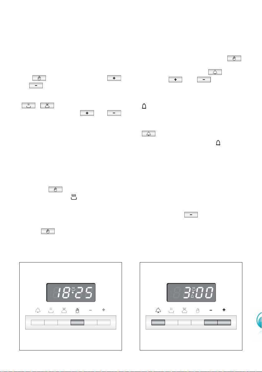
ELECTRONIC CLOCK (fig. 33)
The programmer is equipped with an
electronic clock with lighted numbers
which indicate hours and minutes.
Upon immediate connection of the
oven or after a blackout, three zeroes
will flash on the programmer panel.
To set the hour it is necessary to push
the button and then the
or button until you have set the
exact hour (fig. 33).
Alternatively, simultaneously push the
two buttons and at the
same time push the or
button.
Note: Setting the clock deletes any
programme.
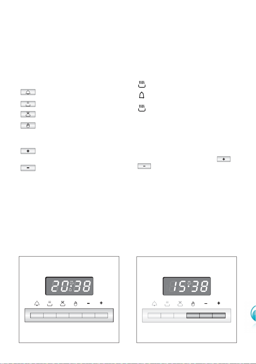
ELECTRONIC TIMER
The timer programme consists only of a
buzzer which may be set for a
maximum period of 23 hours and 59
minutes.
If the AUTO is flashing push the
button.
To set the time, push the button
and the or until you
obtain the desired time (fig. 35).
Having finished the setting, the normal
time will appear on the panel and the
symbol will appear.
The countdown will start immediately
and may be seen at any moment on
the panel by simply pressing the button
.
At the end of the time, the symbol
will be switched off and an intermittent
buzzer will go off; this can be stopped
by pressing any one of the buttons.
ALTERING THE AUDIBLE
SIGNAL
By pressing the button you can
choose from three variations.
NORMAL COOKING
WITHOUT THE USE OF THE
PROGRAMMER
To manually use the oven, that is, without
the aid of the programmer, it is necessary
to cancel the flashing AUTO by pushing
the button (AUTO will be switched
off and the symbol will go on - Fig.
34).
Attention: If the AUTO is not flashing
(which means a cooking programme has
already been inserted), by pushing the
button you have cancelled the
programme and switched to manual.
Figure 34 Figure 35
34
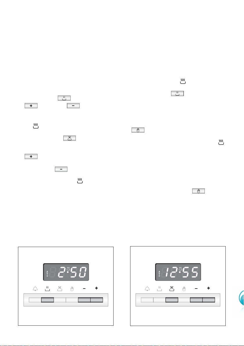
AUTOMATIC OVEN
COOKING
To cook food automatically in the oven,
it is necessary to:
1.Set the length of the cooking time
2.Set the end of the cooking time
3.Set the temperature and the oven
cooking programme.
These operations are done in the
following way:
1.Set the length of the cooking time by
pushing the button and the
button to
advance, or
to go back if you have passed the
desired time (fig. 36). The AUTO and
the symbol will be on.
2.Set the end of the cooking time by
pressing the button (the
cooking time already added to the
clock time will appear), and the
button (fig. 37); if you pass the
desired time you may get back by
pushing the button.
After this setting, the symbol will
go off. If after this setting, the AUTO
flashes on the panel and a buzzer
goes off, it means there was an error
in the programming.
In this case, modify the end of
cooking time or the cooking time
itself by following the above
instructions again.
3.Set the temperature and the cooking
programme by using the switch and
thermostat knobs of the oven (see
specific chapters).
Now the oven is programmed and
everything will work automatically, that
is the oven will turn on at the right
moment to end the cooking at the
established time.
During cooking, the symbol remains
on.
By pushing the button you can
see the time that remains until the end
of cooking.
The cooking programme may be
cancelled in any moment by pushing
.
At the end of the cooking time the
oven will turn off automatically, the
symbol will turn off, AUTO will flash
and a buzzer will sound, which can be
turned off by pushing any of the but-
tons.
Turn the switch and thermostat knobs
to zero and put the programmer onto
“manual” by pressing the button.
Attention: A power cut makes the
clock go to zero and cancels the set
programmes.
After a power cut three zeroes will flash
on the panel.
Figure 37
Figure 36
35
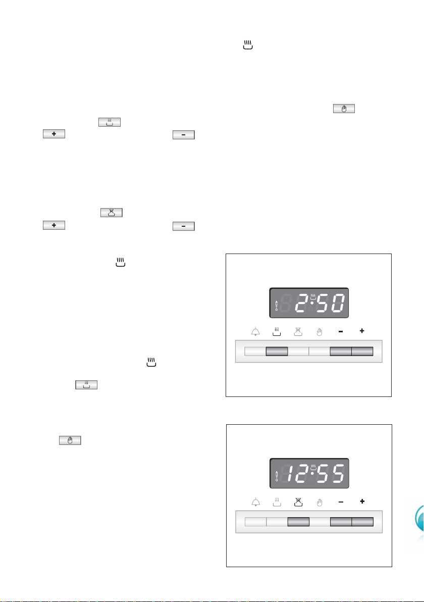
SEMI-AUTOMATIC
COOKING
This is used to automatically switch off
the oven after the desired cooking time
has elapsed.
There are two ways to set your oven:
1. Set the length of the cooking time by
pushing the button and the
button to advance, or
to go backwards if you have passed
the desired time (Fig. 38).
or
2. Set the end of the cooking time by
pushing the button and the
button to advance, or
to go backwards if you have passed
the desired time (Fig. 39).
AUTO and the symbol will be
on.
Then set the temperature and the
cooking programme using the oven
switch and thermostat knobs (see
specific chapters).
The oven is switched on and it will
be switched off automatically at the
end of the desired time.
During cooking, the symbol
remains on and by pressing the
button you can see the time
that remains till the end of the
cooking.
The cooking programme can be
cancelled at any moment by pushing
the button.
At the end of cooking, the oven and
the symbol will turn off, the AUTO
will flash and a buzzer will sound; that
can be stopped by pushing any of the
buttons.
Turn the switch and thermostat knobs
to zero and put the programmer onto
“manual” by pressing the button.
Figure 38
Figure 39
36
GENERAL ADVICE
■ Before you begin cleaning, you must ensure that the appliance is
switched off.
■ It is advisable to clean when the appliance is cold and especially when cleaning
the enamelled parts.
■ Avoid leaving alkaline or acidic substances (lemon juice, vinegar, etc.) on the
surfaces.
■ Avoid using cleaning products with a chlorine or acidic base.
■ Do not use a steam cleaner because the moisture can get into the
appliance thus make it unsafe.
WARNING
When correctly installed, your product meets all safety requirements laid down for this
type of product category. However special care should be taken around the rear or the
underneath of the appliance as these areas are not designed or intended to be
touched and may contain sharp or rough edges, that may cause injury.
ENAMELLED PARTS
All the enamelled parts must be cleaned with a sponge and soapy water only or other
non-abrasive products.
Dry preferably with a microfibre or soft cloth.
STAINLESS STEEL SURFACES
The stainless steel front panels on this cooker (facia, oven door, storage compartment)
are protected by a finger-print proof lacquer. To avoid damaging this lacquer, do not
clean the stainless steel with abrasive cleaners or abrasive cloths or scouring pads.
ONLY SOAP/WARM WATER MUST BE USED TO CLEAN THE STAINLESS STEEL
SURFACES.
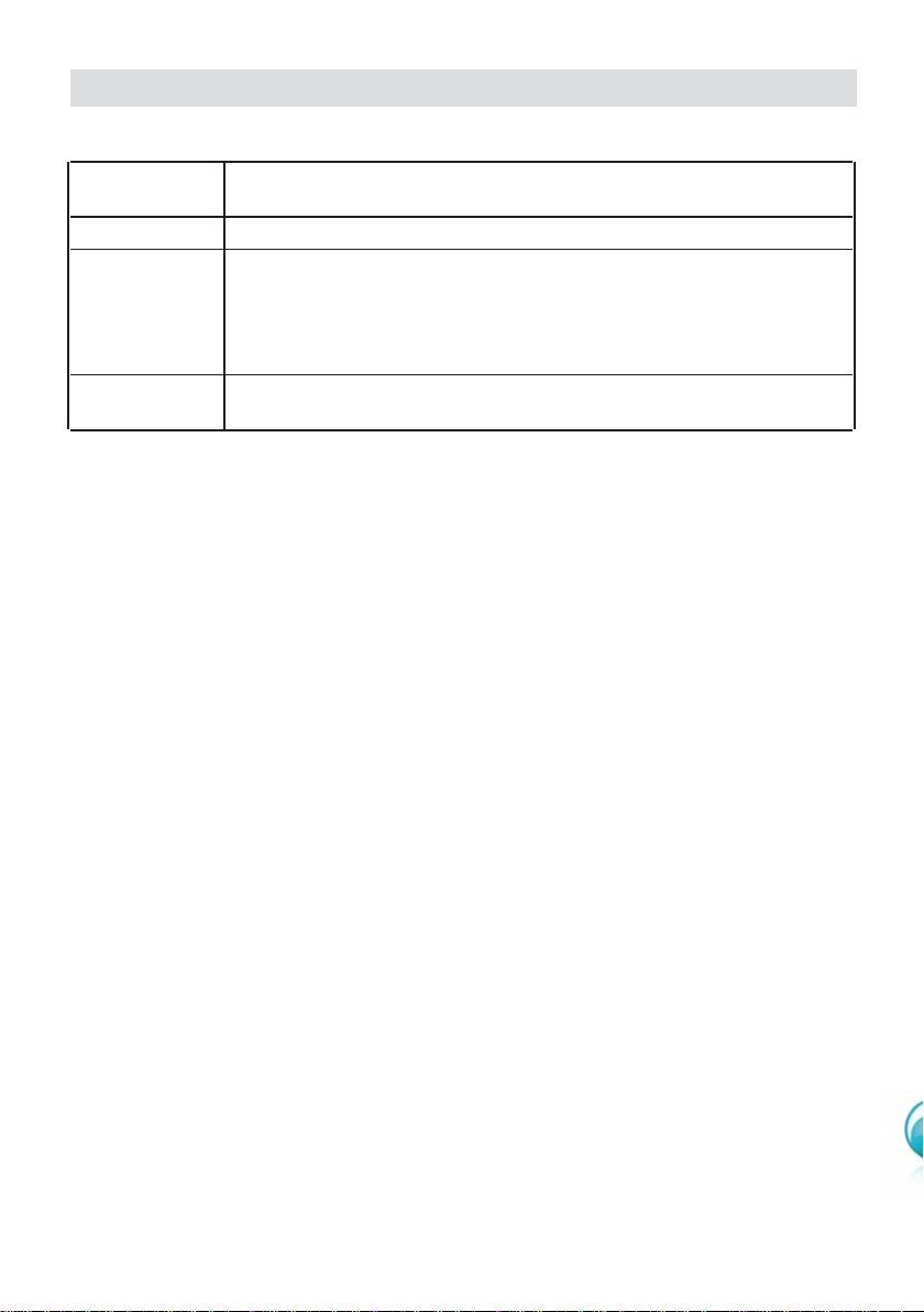
Cleaning and Maintenance
Maintenance
Description
Period
Daily • Clean gas cooktop as per instructions below
• Remove burner caps, burner rings & base and clean using
non abrasive detergent & rinse in cold water & dry thoroughly
Monthly before replacing back on hob
• Clean ignitor tip & thermocouple using damp soapy cloth
and dry thoroughly
3 - 4 Yearly
• Contact your local authorized gas Service Agent to perform
a thorough check on all gas components on the gas cooker

37
INSIDE OF OVEN
■ The oven should always be cleaned after use when it has cooled down.
The cavity should be cleaned using a mild detergent solution and warm water.
Suitable proprietary chemical cleaners may be used after first consulting with the
manufacturers recommendations and testing a small sample of the oven cavity.
Abrasive cleaning agents or scouring pads/cloths should not be used on the cavi-
ty surface.
■ NOTE: The manufacturers of this appliance will accept no responsibility for dam-
age caused by chemical or abrasive cleaning.
■ Do not store flammable material in the oven.
ADVICE FOR USE AND MAINTENANCE OF CATALYTIC
PANELS
The catalytic panels are covered with special microporous enamel which absorbs and
does away with oil and fat splashes during normal baking over 200°C.
If, after cooking very fatty foods, the panels remain dirty, operate the oven “idling” on
max temperature for about 30 minutes. These panels do not require to be cleaned,
however it is advised to periodically remove them from the oven (at least the side pan-
els) and to wash them with tepid soapy water and then wipe off with a soft cloth.
DO NOT CLEAN OR WASH THEM WITH ABRASIVE PRODUCTS OR WITH
PRODUCTS CONTAINING ACIDS OR ALKALIS.
The side panels are reversible and when the catalytic microporous enamel degrades,
they can be turned to the other side.
REPLACING THE OVEN LIGHT BULB
Switch the cooker off at the mains.
When the oven is cool, unscrew and replace the bulb with another one resistant to
high temperatures (300°C), voltage 230-240 V~ (50 Hz), E14
and same power (check
watt power as stamped in the bulb itself) of the replaced bulb.
Note: Oven bulb replacement is not covered by your guarantee.
GRILL HEATING ELEMENT
The heating element is self-cleaning and does not require maintenance.
GAS TAPS
If the gas taps are not working properly, call our Customer Service Centre to obtain the
nearest Authorized Delonghi Service Agent.
38
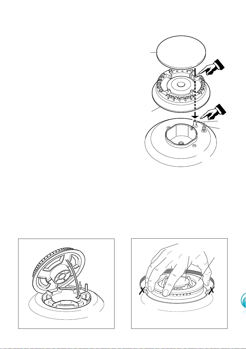
BURNERS
They can be removed and washed only with soapy
water. Detergents can be used but must not be
abrasive or corrosive.
Do not use abrasive sponges or pads.
Do not put in dishwasher.
After each cleaning, make sure that the
burner-caps, as well as the burners, have
been well wiped off and CORRECTLY
POSITIONED.
It is essential to check that the burner flame
distributor F and the cap C has been correctly
positioned (see fig. 40) - failure to do so can
cause serious problems.
Check that the electrode S (fig. 40) is always
clean to ensure trouble-free sparking.
Check that the probe T (fig. 40) next to each
burner is always clean to ensure correct
operation of the safety valves. Both the probe
and ignition plug must be very carefully cleaned.
Note:
The electrode S must be very carefully
cleaned. To avoid damage to the electric
ignition do not use it when the burners are
not in place.
Figure 40
F
C
S
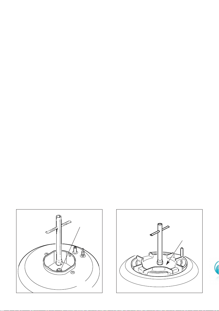
TRIPLE RING BURNER
The triple ring burner must be correctly positioned (see fig. 41); the burner rib must be
located in position as shown by the arrow.
The burner correctly positioned must not rotate (fig. 42).
Then position the cap A and the ring B (fig. 42).
A
B
Figure 41 Figure 42
T
39
Figure 43
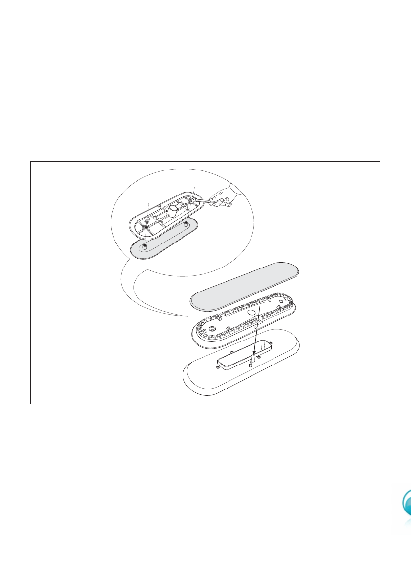
CORRECT POSITION OF THE FISH BURNER
This burner must be correctly positioned as shown in the figure 43.
Both the probe and ignition plug must be very carefully cleaned.
40
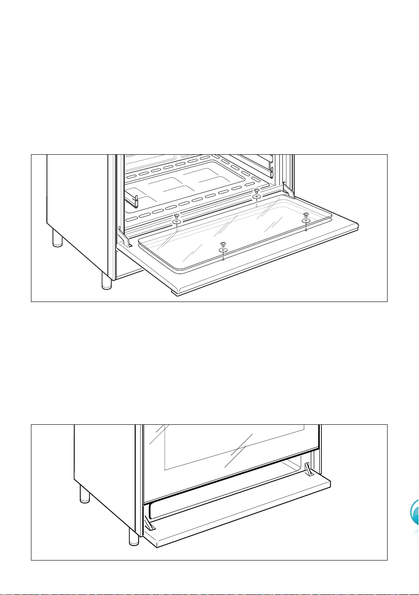
STORAGE COMPARTMENT
■ The storage compartment is accessible through the pivoting panel.
Attention: Do not store flammable material in the oven, or the storage com-
partment.
REMOVAL OF THE INNER GLASS DOOR PANEL
■ The inner glass door panel can easily be removed for cleaning by unscrewing
the four screws (fig. 44).
■ When re-assembly ensure that the inner glass is correctly positioned and do not
over tighten the screws.
Do not use harsh abrasive cleaners or sharp metal scrapers to clean the oven
door glass since they can scratch the surface, which may result in shattering of
the glass.
Figure 44
Figure 45
41
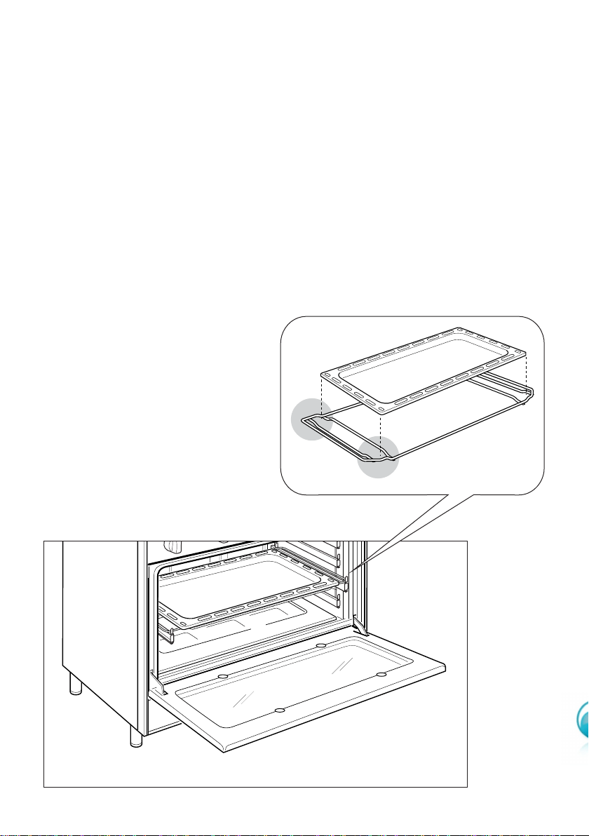
L
F
OVEN TRAY
The oven tray must be placed on its wire shelf support (fig. 46), then correctly insert
into the side runners as per Figure 47. For further instructions see page 19.
OVEN FLOOR
The oven floor F (fig. 47) can be easily removed to facilitate cleaning.
Remember to replace the floor correctly afterwards.
Be careful not to confuse the tray L with the oven floor F.
Figure 46
Figure 47
FRONT
REAR
42
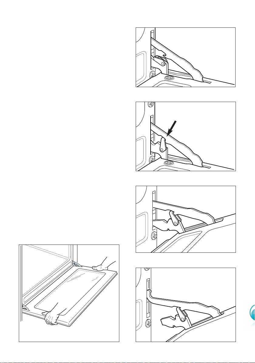
DOOR ASSEMBLY
■ Grip the door (as indicated in fig-
ure 48) and refit it in reverse
order of removal procedure.
DISMANTLING THE DOOR
Please operate as follows:
■ Open the door completely.
■ The swivel retainers of the rh
and lh hinges (fig. 48a) are
hooked onto the metal bar
above them (fig. 48b).
■ Lift the oven door slightly. The
notch on the bottom of the
hinge will disengage (fig. 48c).
■ Now pull the oven door for-
wards off the appliance. Release
both hinge sections from the
slots (fig. 48d).
Figure 48
Figure 48d
Figure 48c
Figure 48b
Figure 48a

43
If the ignition spark fails to ignite or does not light the gas, check the following
items before calling our Customer Service Centre to obtain the nearest Authorised
Service Agent:
■ Burner is reassembled and located correctly.
■ Spark electrode and white ceramic are clean and dry.
■ 240 VAC power supply is connected.
Contact the local gas utility or our Customer Service Centre to obtain the nearest
Authorized Service Agent.
■ You can smell gas when all burners are turned on.
■ The burners do not remain alight at the minimum marked setting.
■ The burner flame is yellow or emits an unusual odour.
Note that a bi-annual inspection of the appliance by an authorized service agent
or your locate gas utility will ensure many years of trouble free operation of your
appliance.
Service and Maintenance
44
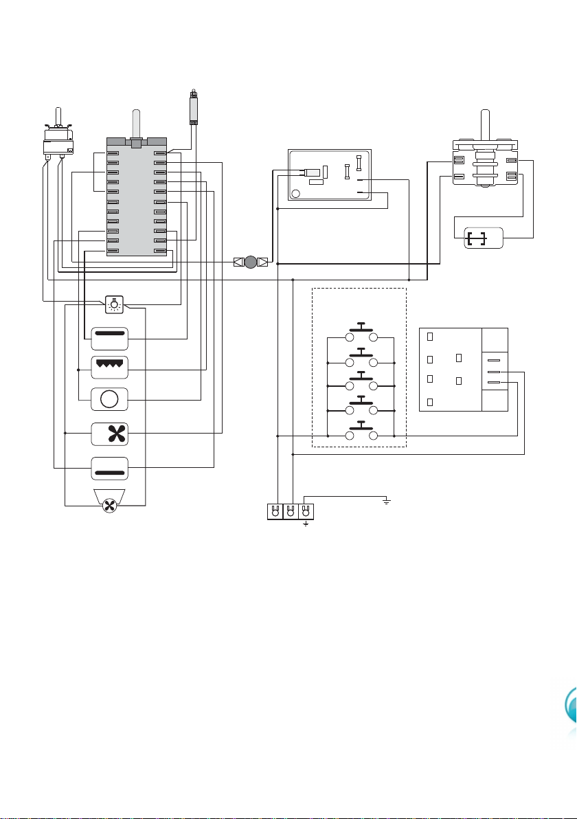
WIRING DIAGRAM
ELECTRIC DIAGRAM KEY
F1 Oven switch
TM Thermostat
LF Oven lamp
F2 Rotisserie switch
GIR Rotisserie
CF Cooling fan
PR Oven programmer
C Top element
G Grill element
V Fan
S Bottom element
TM
C
G
S
V
CIR
S1
LF
F1
N/7
1
1a
L/8
PR
TL
M
N
L
PA
A
T
1
6
1a
6a
4
9
4a
9a
3
8
3a
8a
2
7
2a
7a
5
10
11
5a
10a
11a
CF
F2
GIR
P2 2
P1
1
1131793
CIR Circular element
PA Ignition switches group
A Ignition coil
TL Thermal overload
S1 Thermostat pilot lamp
M Terminal block
T Earth connection

45

46

47
Descriptions and illustrations in this booklet are given as simply indicative. The manufacturer reserves the right,
considering the characteristics of the models described here, at any time and without notice, to make eventual
necessary modifications for their construction or for commercial needs.

cod. 1103188 ß2