INSTALLATION GUIDE
for the
SB-T-TACCAB/10W3v3
SB-T-TACCAB/10W3v3
2005 - Up
2005 - Up
Toyota Tacoma Access Cab
Toyota Tacoma Access Cab
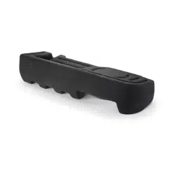
Thank you for choosing a JL Audio Stealthbox
®
for your automotive sound system. With proper
installation, your new vehicle-specific enclosed subwoofer system will deliver years of listening pleasure.
We strongly recommend that you have your new Stealthbox
®
installed by your authorized JL Audio
dealer. The installation professionals employed by your dealer have the necessary tools and experience
to disassemble and reassemble your vehicle properly. Also, keep in mind that your warranty coverage
extends to 2 years if your system is installed or approved by your authorized JL Audio dealer. If you
prefer to perform your own installation, please read this installation guide completely
before beginning the process.
If you choose to perform the installation yourself, it is absolutely vital that
the Stealthbox
®
be properly mounted to the vehicle according to these
instructions. Failure to mount the enclosure properly presents two problems:
1) The sub-bass performance will suffer due to the movement of the enclosure
caused by the force exerted by the woofer(s).
2) A loose enclosure presents a serious safety hazard in the event of a collision
or sudden deceleration.
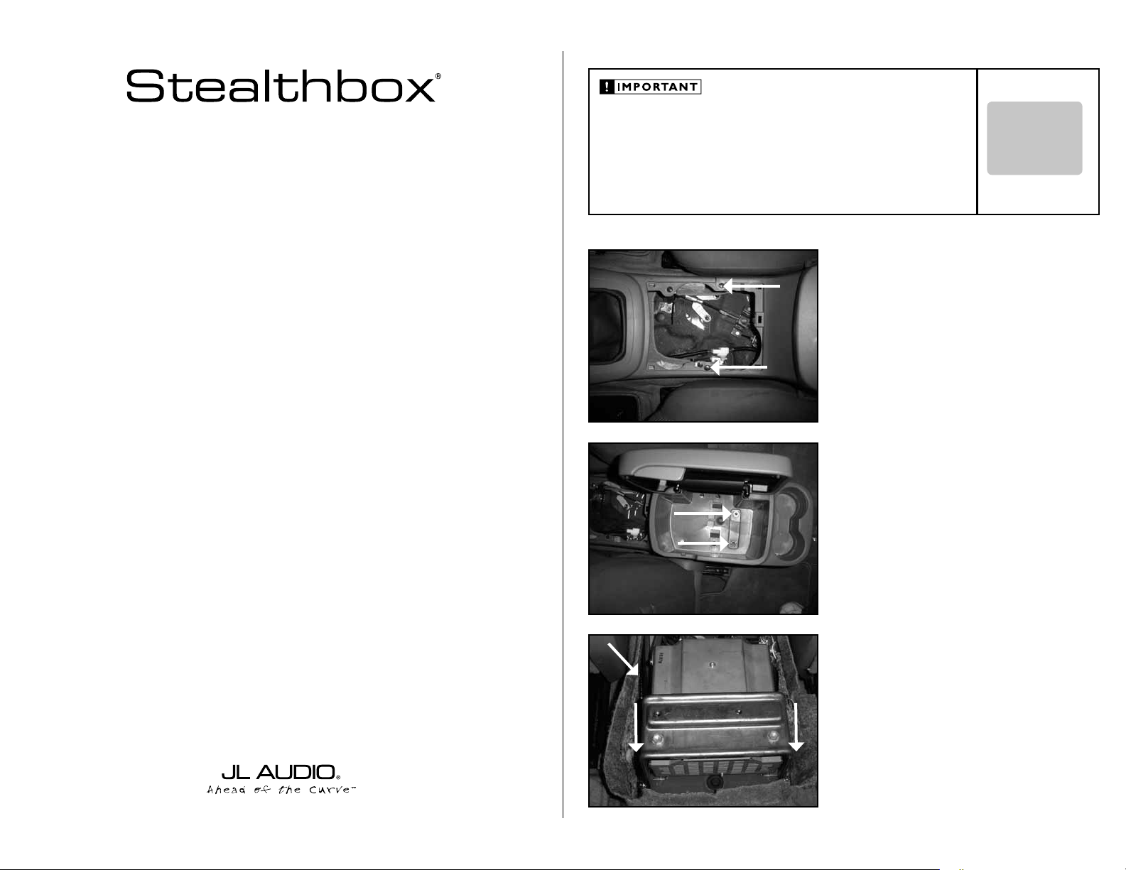
STEP 1
Remove the cup holders from the console.
Remove the pair of screws that are exposed.
Continued on Next Page
STEP 2
Remove the pair of screws that are at the bottom of the
storage bucket.
Remove the console out of the truck.
STEP 3
Remove the three bolts located on the transmission tunnel
that secures the mounting bracket for the AC power inverter.
(If equipped with the AC power inverter)
Unplug the wiring harness from the AC power inverter and
remove out of truck.
If the AC power is to kept, this is up to the installer for proper
relocation, JL Audio® is not responsible.
SB-T-TACCAB/10W3v3_INSTR_SKU#011230
SB-T-TACCAB/10W3v3_INSTR_SKU#011230
INSTALLATION
DIFFICULTY:
2
5
OUT
OF
ESTIMATED TIME:
12 HOUR
12 HOUR
Continued on Next Page
SB-T-TACCAB/10W3v3_INSTR_SKU#011230
SB-T-TACCAB/10W3v3_INSTR_SKU#011230
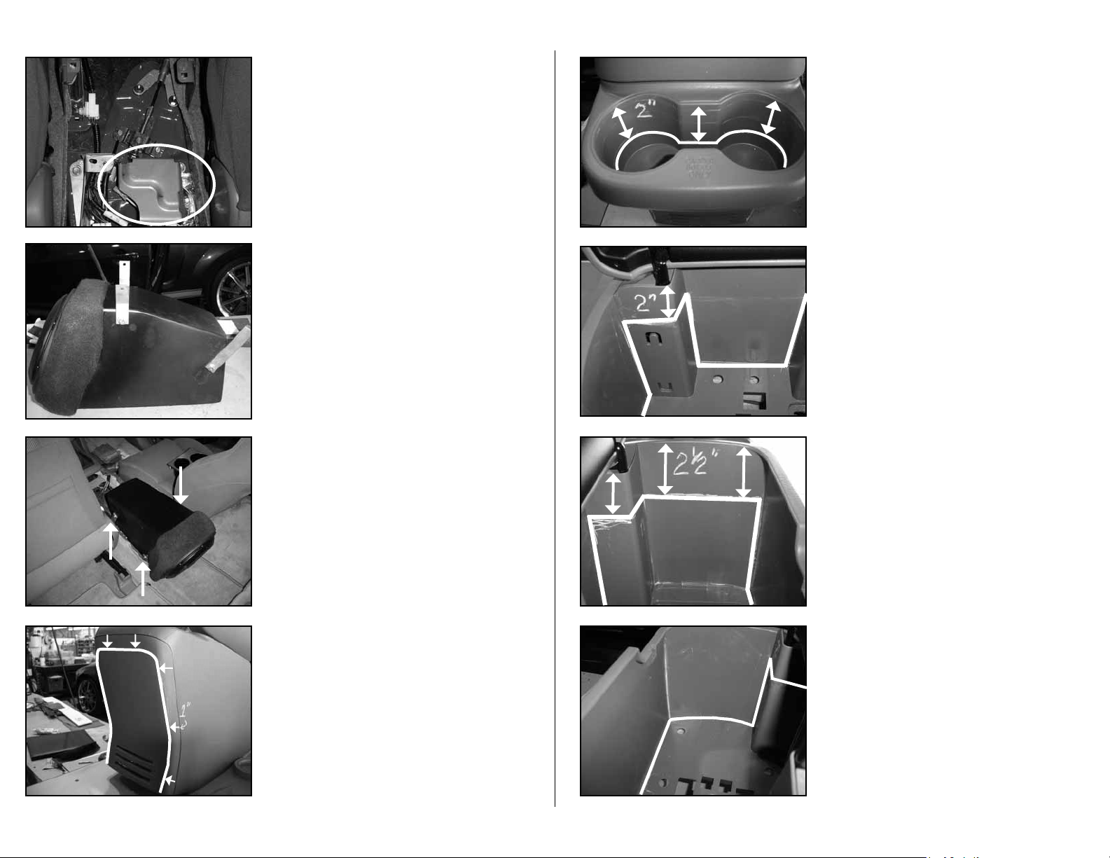
STEP 6
Measure and mark 1-inch from the rear panel’s edge to the
middle of the rear panel. The mark is on both sides and the
top.
Cut on the marked line and remove the center section.
STEP 6
Run speaker wire form the amplifier’s location to the
Stealthbox®. Wire to the terminal and check the woofer for
proper operation.
Place the Stealthbox® into the mounting location.
Using the three factory bolts that where removed in
STEP 3, secure the bottom of each mounting bracket to the
transmission tunnel.
Tighten all six mounting bolt assemblies.
STEP 5
Place a supplied lock washer, flat washer and mounting
bracket onto three of the supplied bolts.
The two shorter length brackets mount close to the woofer.
Make sure that all three mounting brackets tapper out from
the enclosure, not tapper in.
Only hand tighten the mounting assembly at this time.
STEP 4
Cut off this portion of the bracket as close to the
transmission tunnel as possible.
Page 2 • JL Audio, Inc 2006
STEP 8
*IMPORTANT*
This picture is looking inside the center console with the lid
open. The front of the console it to the left.
Measure and mark 2-inches from the top of the center
console down. Follow the lines in the picture.
STEP 10
*IMPORTANT*
This picture is looking inside the center console with the lid
open. The picture is facing the front of the console.
Cut on the complete marked line. Do not cut into the outer
walls, these are not double layered. Only cut into the floor
and into the stand outs for the legs of the lid.
STEP 9
*IMPORTANT*
This picture is looking inside the center console with the lid
open. The picture is facing the rear of the console.
Measure and mark 2 1/2-inches from the top of the center
console down. Follow the lines in the picture.
STEP 7
Measure and mark 2-inches from the top of the
cup holders down. The mark goes all the way around the
cup holder section.
Cut on the marked line and remove the bottom of the
cup holders.
SB-T-TACCAB/10W3v3_INSTR_SKU#011230
SB-T-TACCAB/10W3v3_INSTR_SKU#011230
CONGRATULATIONS
You have completed the installation for this model!
Please refer to the Power Recommendation section for an
amplifier recommendation and basic set-up help.
STEP 10
Place the screws and cup holders that were removed
in STEP 1.
STEP 11
Place the supplied L-bracket onto the Stealthbox®, as in the
picture.
With a 7/64-inch drill bit and drill, drill pilot holes into the
Stealthbox® only. With the supplied screws, mount the
L-bracket to the Stealthbox® and to the center console.
Place the supplied black carpet panels into the storage
bucket and the rear cup holder areas.
STEP 10
Place the center console on top of the Stealthbox.
This rear portion of the console has ears that stick out the
front on the side walls. These ears need to be placed into the
inside of the walls of the front position of the console.
Page 3 • JL Audio, Inc 2006
All specifications are subject to change without notice. “JL Audio®” and the JL Audio logo, “Stealthbox” and the Stealthbox logo are registered
trademarks of JL Audio, Inc. “Ahead of the Curve” and its respective logo is a trademark of JL Audio, Inc.
JLA-SKU#011230-05-07-200
JLA-SKU#011230-05-07-200
7
7
• Printed in USA • ©2005 JL Audio, Inc. • U.S. PATENTS: #5,734,734 #5,949,898 #6,118,884 #6,229,902
#6,243,479 #6,294,959 #6,501,844 #6,496,590 #6,441,685 #5,687,247 #6,219,431 #6,625,292 #D472,891 #D480,709 Other U.S. & Foreign
patents pending. For more detailed information please visit us online at www.jlaudio.com.
(954) 443-1100
www.jlaudio.com
10369 NORTH COMMERCE PARKWAY • MIRAMAR, FLORIDA • 33025 • USA
INCLUDED HARDWARE
(3)
(3)
1/4-inch -20 x 1-1/2-inch Hex Bolts
1/4-inch -20 x 1-1/2-inch Hex Bolts
(2)
(2)
Custom Short Mounting Bracket
Custom Short Mounting Bracket
(3)
(3)
1/4-inch x 3/4-inch US
1/4-inch x 3/4-inch US
S Flat Washer
S Flat Washer
(1)
(1)
Aluminum L-Bracket
Aluminum L-Bracket
(3)
(3)
1/4-inch x 1 1/4-inch Lock Washer
1/4-inch x 1 1/4-inch Lock Washer
(
(
3)
3)
Flat Head Machine Screws
Flat Head Machine Screws
(1)
(1)
Custom Long Mounting Bracket
Custom Long Mounting Bracket
SPECIFICATIONS
Enclosure Type:
Acoustic Suspension (sealed)
Acoustic Suspension (sealed)
Driver Type:
10W3v3-4
10W3v3-4
Nominal Impedance:
4 ohms mono
4 ohms mono
Continuous Power Handling:
300 Watts
300 Watts
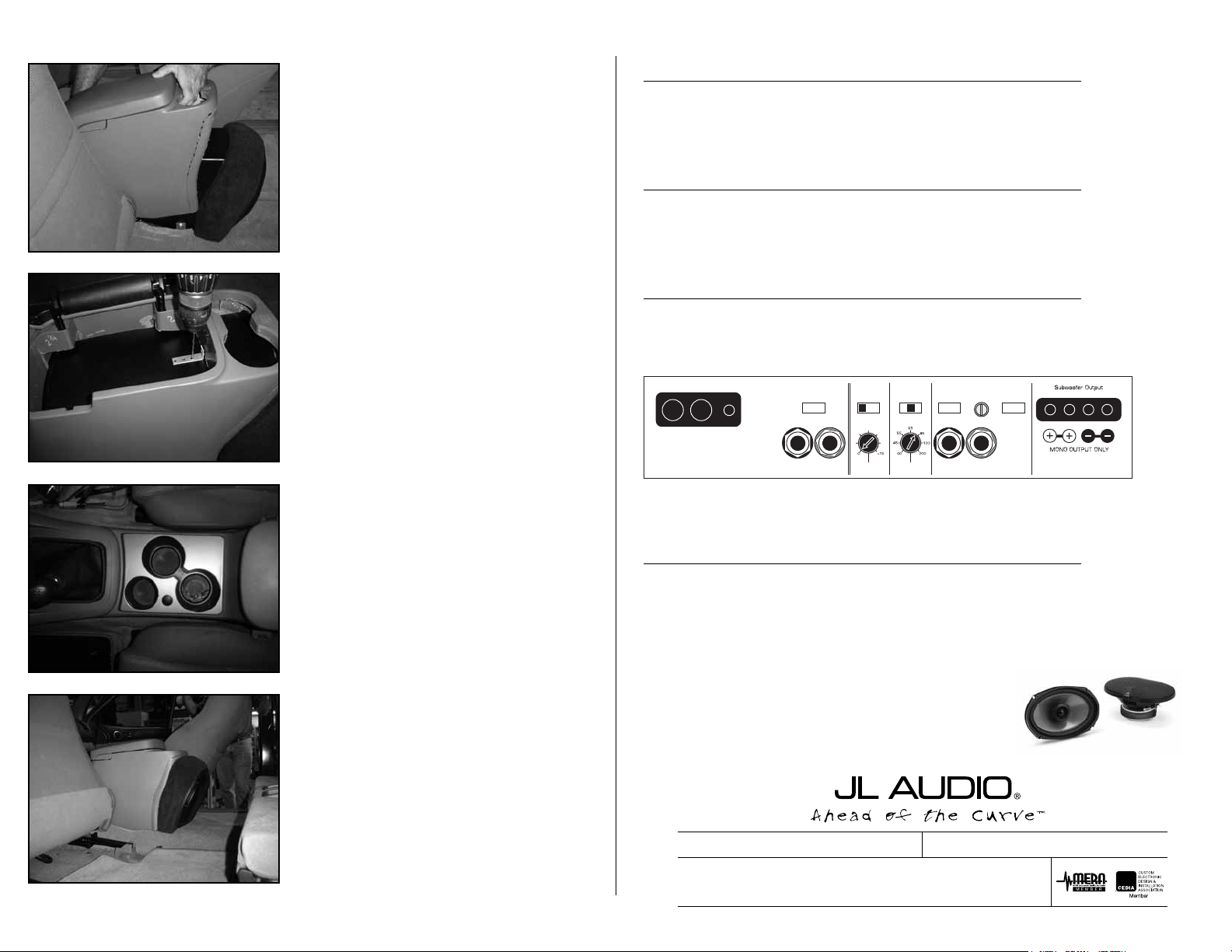
POWER RECOMMENDATION
JL Audio recommends using a high quality amplifier such as the JL Audio 250/1.
The diagram below shows the recommended crossover, infrasonic filter and equalizer settings for the 250/1 when
being used to power your Stealthbox
®
.
JL AUDIO 250/1
monoblock subwoofer amplifier
Amplifier Input Section
Input Sens.
Input Voltage
Low/High
Left Ch.
Right Ch.
Signal Sensing
Off/On
Output Mode
Full-Range/Low-Pass/High-Pass
Left Ch.
Right Ch.
Amp LP Filter
Mode/Slope
Off/12dB/24dB
Filter Freq. (Hz)
Bass Control
LF Boost (dB)
Off/30Hz
Infrasonic Filter
+1
+13
+3
+7
+10
Preamp Output Section
+12VDC Ground Remote
The JL Audio 250/1 is a very versatile audio component. Please consult the owner’s manual for even more
detailed information about installing and tuning this amplifier.
MID/HIGH FREQUENCY DRIVER FITMENT
A variety of JL Audio coaxial and component systems will fit in the factory speaker locations of you vehicle.
Front Speaker Size / Location:
6-inch x 9-inch Separates / Front Doors
6-inch x 9-inch Separates / Front Doors
Fits JL Audio Models*:
TR690-TXi & VR690-CSI
TR690-TXi & VR690-CSI
Rear Speaker Size / Location:
6.5-inch / Rear Doors
6.5-inch / Rear Doors
Fits JL Audio Models*:
TR650-CXi, TR650CSi, VR650-CXi, VR650-CSi,
TR650-CXi, TR650CSi, VR650-CXi, VR650-CSi,
XR525-CXi, XR525-CSi, C5-525x, C5-525 & ZR525-CSi
XR525-CXi, XR525-CSi, C5-525x, C5-525 & ZR525-CSi
* All speakers require custom adaptors for installation
* All speakers require custom adaptors for installation