
Loading ...
Loading ...
Loading ...
The expansion zones may be wired to either the top or bottom communication terminals on the main panel
or to the top or bottom communication terminals on the expansion panel. This wiring flexibility allows the
installer to choose the most flexible, cost effective wiring for the installation.
Each expansion panel must have a 5 Wire connection for proper communication. It is not necessary to use
shielded wire for the panel to panel connection. 18 - 20 Gauge solid thermostat wire or similar is acceptable.
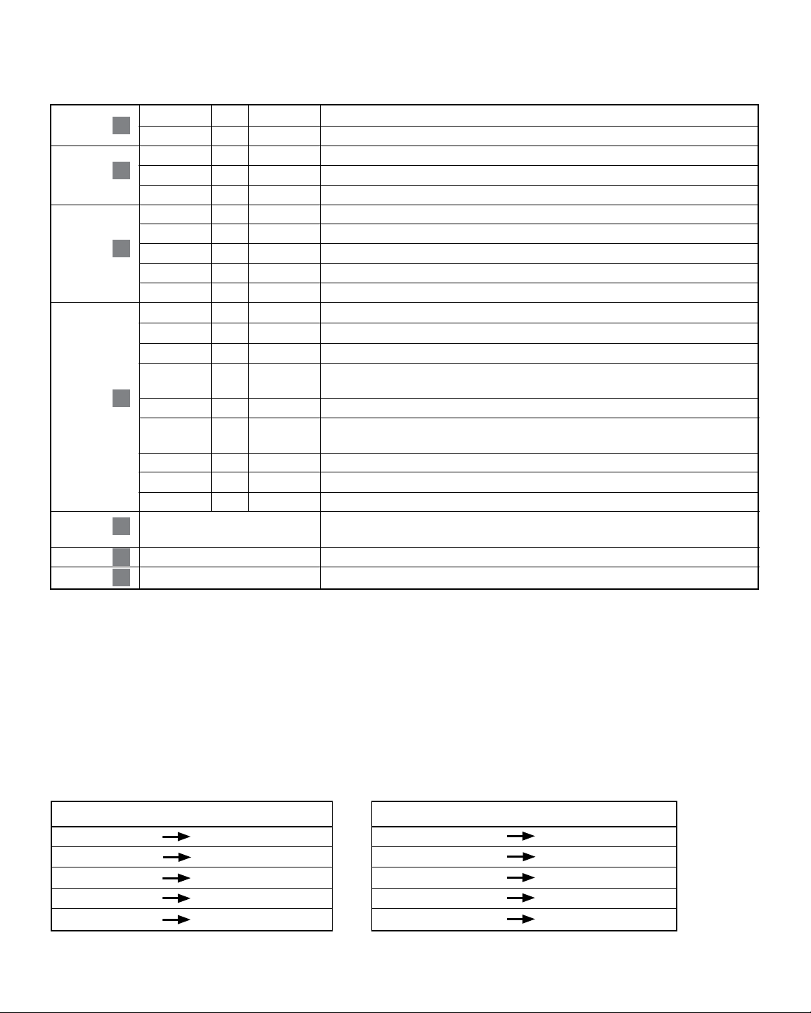
When wiring the expansion panels be sure to connect the terminals from one panel to the next using the
following terminal connections.
5
Main Panel to Expansion Panel
COM1 COM1
COM2 COM2
GND GND
COM3 COM3
COM4 COM4
Expansion Panel to Expansion Panel
COM1 COM1
COM2 COM2
GND GND
COM3 COM3
COM4 COM4
MAIN Panel to Expander
Expander to Expander
Terminal
Qty.
Function Description
PANEL 24V 1 INPUT 24 VAC Transformer Power 75 VA Maximum
POWER 24C 1 INPUT 24 VAC Transformer Common
DAMPERS PO 2 OUTPUT 24 VAC Power Open Zone Damper Terminal
C 2 OUTPUT Zone Damper Common Terminal
PC 2 OUTPUT 24 VAC Power Close Zone Damper Terminal
EXPANSION COM1 2 OUTPUT Expander Panel Communication
COM2 2 OUTPUT Expander Panel Communication
GND 2 INPUT Expander Panel Communication Ground
COM3 2 INPUT Expander Panel Communication
COM4 2 INPUT Expander Panel Communication
THERMOSTAT R 2 OUTPUT 24 VAC Thermostat Power
Y1 2 INPUT 1st Stage Compressor Call
Y2 2 INPUT 2nd Stage Compressor Call
W1/E/AX1 2 INPUT [W1] 1st Stage Conventional Heat Call [E] Emergency Heat Call
[AX1] 1st Stage Auxiliary Heat Call
W2/AX2 2 INPUT [W2] 2nd Stage Conventional Heat Call [AX2] 2nd Stage Auxiliary Heat Call
O/B/W3 2 INPUT [O] Cool Active Reversing Valve Call [B] Heat Active Reversing Valve Call
[W3] 3rd Stage Conventional Heat Call
G 2 INPUT Fan Call
L 2 OUTPUT System Malfunction Indicator
C 2 OUTPUT 24 VAC Transformer Common
RESET BUTTON Press once to restart panel
Hold for 5 seconds to reset panel and reset all factory defaults.
ZONE ADDRESS DIP SWITCHES See Zone Addressing (section 4)
WIRE STRIP GUIDE Wires should be stripped 3/8 inch minimum.
ZONE PANEL EXPANDER WIRING TERMINALS
1
2
3
4
5
6
7
Loading ...
Loading ...
Loading ...