Business Networking Solution
Installation Guide
10/100Mbps Unmanaged Switch
TL-SF1016/TL-SF1016DS
TL-SF1024/TL-SF1024D
TL-SF1048

I
About this Installation Guide
About this Installation Guide
This Installation Guide describes the hardware characteristics, installation methods and the
points that should be attended to during the installation. This Installation Guide is structured as
follows:
Chapter 1 Introduction.
This chapter describes the external components of the switch.
Chapter 2 Installation.
This chapter illustrates how to install the switch.
Chapter 3 Lightning Protection.
This chapter illustrates how to prevent lightning damage.
Chapter 4 Connection.
This chapter illustrates how to do the physical connection of the switch.
Appendix A Troubleshooting.
Appendix B Specifications.
Audience
This Installation Guide is for:
Network Engineer Network Administrator
Conventions
• Some models featured in this guide may be unavailable in your country or region. For local sales
information, visit http://www.tp-link.com.
• The figures in Chapter 2 to Chapter 4 are for demonstration purposes only. Your switch may differ
in appearance from that depicted.
• This Guide uses the specific formats to highlight special messages. The following table lists the
notice icons that are used throughout this guide.
Remind to be careful. A caution indicates a potential which may result in device damage.
Remind to take notice. The note contains the helpful information for a better use of the
product.
Related Document
This Installation Guide is also available in PDF on our website. To obtain the latest
documentation and product information, please visit the official website:
http://www.tp-link.com

IIContents
Contents
Chapter 1 Introduction ——————————— 01
1.1 Product Overview ...........................................................01
1.2 Appearance .......................................................................01
Chapter 2 Installation ——————————— 04
2.1 Package Contents ..........................................................04
2.2 Safety Precautions .........................................................04
2.3 Installation Tools ..............................................................06
2.4 Product Installation ........................................................07
Chapter 3 Lightning Protection ——————— 09
3.1 Cabling Reasonably........................................................09
3.2 Connect to Ground .........................................................11
Chapter 4 Connection ——————————— 15
4.1 Ethernet Port ....................................................................15
4.2 Verify Installation .............................................................15
4.3 Power On ............................................................................15
4.4 Initialization ........................................................................16
Appendix A Troubleshooting ———————— 17
Appendix B Specications ————————— 18

10/100Mbps Unmanaged Switch
01 Introduction
Chapter 1 Introduction
1.1 Product Overview
TL-SF1016/TL-SF1016DS/TL-SF1024/TL-SF1024D/TL-SF1048 switch provides
16/24/48 10/100Mbps Auto-Negotiation RJ45 ports. Each port of the TL-SF1016/TL-
SF1016DS/ TL-SF1024/TL-SF1024D/TL-SF1048 supports auto MDI/MDI-X function,
eliminating the need for crossover cables or Uplink ports. The switch is Plug-and-Play
and any port can be simply plugged into a server, a hub or a switch, using straight cable
or crossover cable.
The TL-SF1016/TL-SF1016DS/TL-SF1024/TL-SF1024D/TL-SF1048 16/24/48-port
10/100Mbps Fast Ethernet Switch provides you with a low-cost, easy-to-use, high-
performance, seamless and standard upgrade to improve your old network to a
100Mbps network. It will boost your network performance up to full duplex data
transfer.
1.2 Appearance
■
Front Panel
The front panel of TL-SF1016 is shown as the following figure.
Figure 1-1 Front Panel of TL-SF1016
10/100Mbps
RJ45 Port
LEDs
The front panel of TL-SF1016DS is shown as the following figure.
Figure 1-2 Front Panel of TL-SF1016DS
10/100Mbps
RJ45 Port
LEDs

10/100Mbps Unmanaged Switch
02Introduction
The front panel of The TL-SF1024 is shown as the following figure.
Figure 1-3 Front Panel of TL-SF1024
10/100Mbps
RJ45 Port
LEDs
The front panel of The TL-SF1024D is shown as the following figure.
Figure 1-4 Front Panel of TL-SF1024D
10/100Mbps
RJ45 Port
LEDs
The front panel of The TL-SF1048 is shown as the following figure.
Figure 1-5 Front Panel of TL-SF1048
10/100Mbps
RJ45 Port
LEDs
LEDs
LED Status Indication
Power
On The switch is powered on
Off
The switch is powered off or power supply is
abnormal
Flashing Power supply is abnormal
Link/Act
On A device is linked to the corresponding port
Flashing Data is being transmitted or received
Off There is no device linked to the corresponding port

10/100Mbps Unmanaged Switch
04Installation
Chapter 2 Installation
2.1 Package Contents
Make sure that the package contains the following items. If any of the listed items is
damaged or missing, please contact your distributor.
One Power Cord
One Switch
This Installation Guide
Installation Guide
Business Networking Solution
Two mounting brackets and
the ttings
2.2 Safety Precautions
To avoid any device damage and bodily injury caused by improper use, please observe
the following rules.
■
Safety Precautions
■
Keep the power off during the installation.
■
Wear an ESD-preventive wrist strap, and make sure that the wrist strap has a good skin
contact and is well grounded.
■
Use only the power cord provided with the switch.
■
Make sure that the supply voltage matches the specifications indicated on the rear
panel of the switch.
■
Ensure the vent hole is well ventilated and unblocked.
■
Do not open or remove the cover of the switch.
■
Before cleaning the device, cut off the power supply. Do not clean it by the waterish
cloth, and never use any other liquid cleaning method.
10/100Mbps Unmanaged Switch
05 Installation
■
Site Requirements
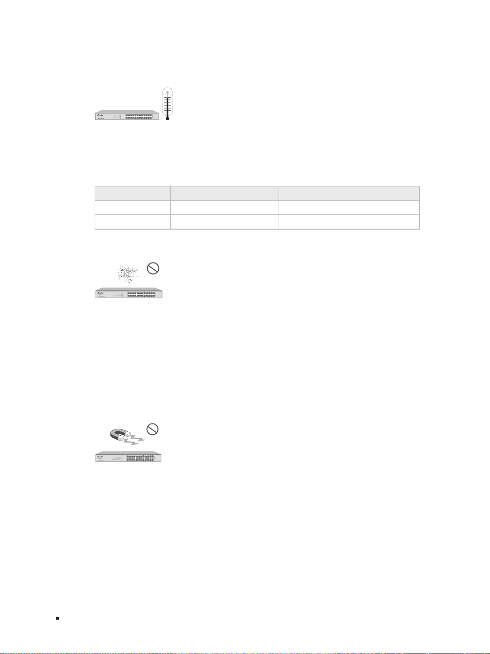
Temperature/Humidity
40℃
0℃
Please keep a proper temperature and humidity in the equipment room. Too high/low
humidity may lead to bad insulation, electricity leakage, mechanical property changes
and corrosions. Too high temperature may accelerate aging of the insulation materials
and can thus significantly shorten the service life of the device. For normal temperature
and humidity of the device, please check the following table.
Environment Temperature Humidity
Operating 0
℃
to 40
℃
10% to 90%RH Non-condensing
Storage -40
℃
to 70
℃
5% to 90%RH Non-condensing
Clearness
The dust accumulated on the switch can be absorbed by static electricity and result
in poor contact of metal contact points. Some measures have been taken for the
device to prevent static electricity, but too strong static electricity can cause deadly
damage to the electronic elements on the internal circuit board. To avoid the effect of
static electricity on the operation of the Switch, please attach much importance to the
following items:
■
Dust the device regularly, and keep the indoor air clean.
■
Keep the device well grounded and ensure static electricity has been transferred.
Electromagnetic Interference
Electronic elements including capacitance and inductance on the device can be
affected by external interferences, such as conducted emission by capacitance
coupling, inductance coupling, and impedance coupling. To decrease the interferences,
please make sure to take the following measures:
■
Use the power supply that can effectively filter interference from the power grid.
■
Keep the device far from high-frequency, strong-current devices, such as radio
transmitting station.
■
Use electromagnetic shielding when necessary.

10/100Mbps Unmanaged Switch
06Installation
Lightening Protection
Extremely high voltage currents can be produced instantly when lightning occurs and
the air in the electric discharge path can be instantly heated up to 20,000
℃
. As this
instant current is strong enough to damage electronic devices, more effective lightning
protection measures should be taken.
■
Ensure the rack and device are well earthed.
■
Make sure the power socket has a good contact with the ground.
■
Keep a reasonable cabling system and avoid induced lightning.
■
Use the signal SPD (Surge Protective Device) when wiring outdoor.
Note:
For detailed lightning protection measures, please refer to Chapter 3 Lightning
Protection.
Installation Site
When installing the device on a rack or a flat workbench, please note the following
items:
■
The rack or workbench is flat and stable, and sturdy enough to support the weight of
5.5kg at least.
■
The rack or workbench has a good ventilation system. The equipment room is well
ventilated.
■
The rack is well grounded. Keep the power socket less than 1.5 meters away from the
device.
2.3 Installation Tools
■
Phillips screwdriver
■
ESD-preventive wrist wrap
■
Cables
Note:
These tools are not provided with our product. If needed, please self purchase
them.

10/100Mbps Unmanaged Switch
08Installation
3. After the brackets are attached to the device, use suitable screws (not provided) to
secure the brackets to the rack, as illustrated in the following figure.
Figure 2-3 Rack Installation
Rack
Caution:
■
Please set 5 to 10cm gaps around the device for air circulation.
■
Please avoid any heavy thing placed on the device.
■
Please mount devices in sequence from the bottom to top of the rack and ensure
a certain clearance between devices for the purpose of heat dissipation.

10/100Mbps Unmanaged Switch
09 Lightning Protection
Chapter 3 Lightning Protection
3.1 Cabling Reasonably
In the actual network environment, you may need cable outdoors and indoors, and
the requirements for cabling outdoors and indoors are different. A reasonable cabling
system can decrease the damage of induced lightning to devices.
Note:
It's not recommended using Ethernet cables outdoors. When cabling outdoors,
please use a signal lightning arrester.
■
Requirements for Cabling Outdoors
■
Aerial cabling without safeguard is not allowed.
■
It’s not allowed cabling down the building to connect network devices in different
floors.
■
Outdoor cables should be buried and paved to the indoor through basement. A piece of
steel wire should be paved underground along the pipe and connected to the lightning
protection terminal of the building for shielding. Before connecting the cable to the
device, install a signal lightning arrester on the corresponding port.
■
When an aerial cable is set up, the cable should be through a metal pipe (15m long
at least) before coming into the building. The two ends of this metal pipe should be
grounded. Before connecting the cable to the device, install a signal lightning arrester
on the corresponding port.
■
It’s not necessary to pave STP cables through pipes. The shielded layer of STP cable
should be well grounded. Before connecting the cable to the device, install a signal
lightning arrester on the corresponding port.
10/100Mbps Unmanaged Switch
10Lightning Protection
■
Requirements for Cabling Indoors
When cabling indoors, keep a certain distance away from the devices that may cause
high-frequency interferences, such as down-conductor cable, powerline, power
transformer and electromotor.
■
The main cable should be paved in the metal raceway of the access shaft. When
cabling, keep the loop area formed by the cable itself as small as possible.
■
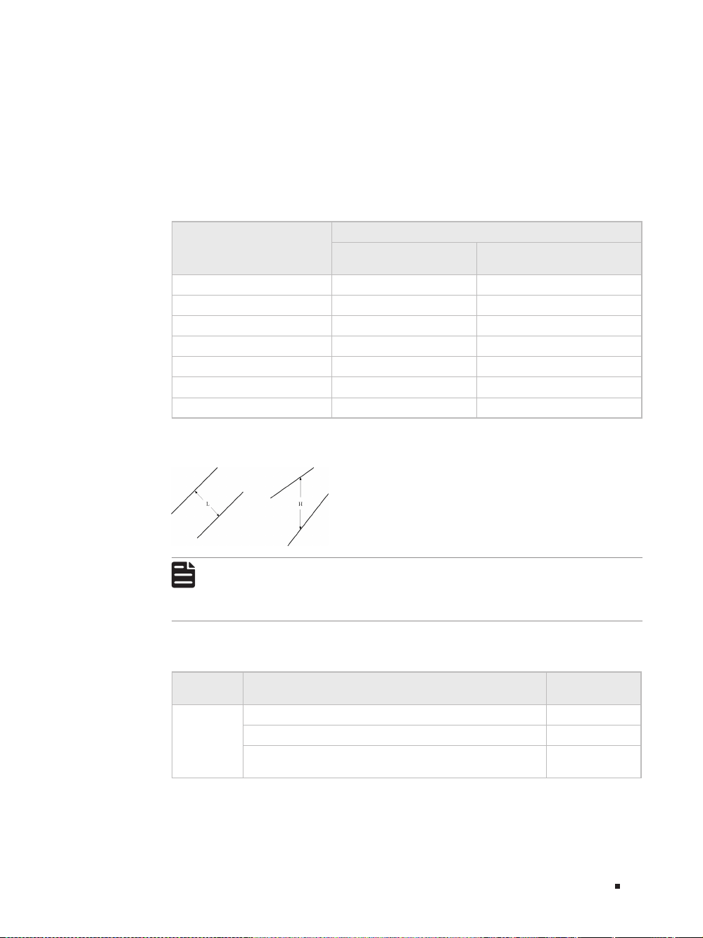
Requirements for the distance between Ethernet cable and other pipelines are shown
in the table.
Other Pipelines
Ethernet Cable
Min Parallel Net Length
L (mm)
Min Parallel-overlapping Net
Height H (mm)
Down-conductor 1000 300
PE 50 20
Service pipe 150 20
Compressed air pipe 150 20
Thermal pipe (not wrapped) 500 500
Thermal pipe (wrapped) 300 300
Gas pipe 300 20
The two diagrams below demonstrate parallel net length and parallel-overlapping
net height.
Note:
The above minimum net length/height is required when metal raceway is not
used. If any requirements cannot be met, you can add a steel tube or metal
raceway for shielding.
■
Requirements for the distance between Ethernet cable and high-power electric devices
are in following tables.
Cable Pave Way
Min Parallel
Length (mm)
<2kVA
powerline
Parallel cabling 130
One is in the grounded metal raceway or metal pipe 70
The both are in the grounded metal raceway or metal
pipe
10

10/100Mbps Unmanaged Switch
11 Lightning Protection
Cable Pave Way
Min Parallel
Length (mm)
2 to 5kVA
powerline
Parallel cabling 300
One is in the grounded metal raceway or metal pipe 150
The both are in the grounded metal raceway or metal
pipe
80
>5kVA
powerline
Parallel cabling 600
One is in the grounded metal raceway or metal pipe 300
The both are in the grounded metal raceway or metal
pipe
150
Device Min Distance (m)
Switch case 1.00
Transformer room 2.00
Elevator tower 2.00
Air-conditioner room 2.00
3.2 Connect to Ground
Connecting the device to ground is to quickly release the lightning over-voltage and
over-current of the device, which is also a necessary measure to protect the body from
electric shock.
In different environments, the device may be grounded differently. The following
will instruct you to connect the device to the ground in two ways, connecting to the
grounding bar or connecting to the ground via the power cord. Please connect the
device to ground in the optimum way according to your specific operation environment.
■
Connecting to the Ground via the Power Supply
If the device is installed in the normal environment, the device can be grounded via the
PE (Protecting Earth) cable of the AC power supply as shown in the following figure.
Figure 3-4 Connecting to the Ground
Switch (Rear Panel)
AC Power Cord (with PE cable)

10/100Mbps Unmanaged Switch
12Lightning Protection
Note:
■
The figure is to illustrate the application and principle. The power plug you get from
the package and the socket in your situation will comply with the regulation in your
country, so they may differ from the figure above.
■
If you intend to connect the device to the ground via the PE (Protecting Earth)
cable of AC power cord, please make sure the PE (Protecting Earth) cable in the
electrical outlet is well grounded in advance.
■
Connecting to the Grounding Bar
Use the grounding bar
If the device is installed in the Equipment Room, where a grounding bar is available, you
are recommended to connect the device to the grounding bar as shown in the following
figure.
Figure 3-5 Connecting to the Grounding Bar
Switch (Rear Panel)
Ground Cable
Grounding Terminal
Grounding Bar
Note:
The grounding bar and the ground cable are not provided with our product. If
needed, please self purchase them.
Equipotential Bonding
Equipotential Bonding is the practice of intentionally electrically connecting all earthed
systems to the same grounding grid or connecting the grounding grids of all the
earthed systems together through the ground or overground metal so as to create
an earthed equipotential zone. When lightning occurs, the high voltage produced by
lightning current in all systems will meanwhile exist in their ground cables, and thus all
ground cables have the same electrical potential and basically eliminate the electric
strikes between the systems.

10/100Mbps Unmanaged Switch
13 Lightning Protection
The figure below illustrates how to practice equipotential bonding in a network.
Figure 3-6 Equipotential Bonding
Grounding Terminal Equipotential Bonding Cable
Grounding Bar
Ground Cable
When equipotential bonding, please note that the cable should be copper wrapped
Kelly with its area being 6mm
2
at least. The shorter cable the better, and use a
grounding bar to establish an equipotential bonding point.
Note:
The equipotential bonding cable and ground cable are not provided with our
product. If needed, please self purchase it.
Use Lightning Arrester
Power lightning arrester and signal lightning arrester are used for lighting protection.
Power lightning arrester is used for limiting the voltage surge due to a lightning. If an
outdoor AC power cord should be directly connected to the device, please use a power
lightning arrester.
Note:
Power lightning arrester is not provided with our product. If needed, please self
purchase it.
Signal lightning arrester is used to protect RJ45 ports of the device from lightning.
When cabling outdoors, please install a signal lightning arrester before connecting the
cable to the device.
When purchasing or using a signal lightning arrester, please observe the following
rules:
■
The port rate of the signal lightning arrester should match the rate of the desired port
on the device. If it is not matched, this signal lighting arrester will not work. Purchase a
standard lightning arrester.
10/100Mbps Unmanaged Switch
14Lightning Protection
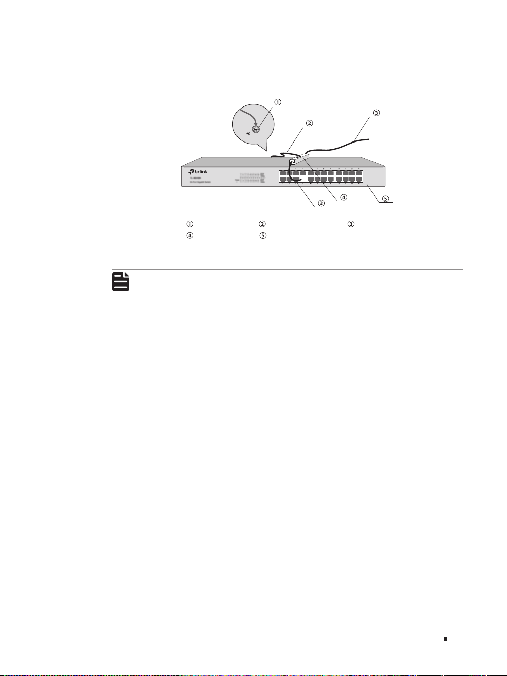
■
Install signal lightning arrester near the protected device and connect it to the ground
via a shorter ground cable.
Figure 3-7 Equipotential Bonding
Ethernet CableEquipotential Bonding CableGrounding Terminal
Signal Lightning Arrester Device
Note:
Signal lightning arrester is not provided with our product. If needed, please self
purchase it.
10/100Mbps Unmanaged Switch
15 Connection
Chapter 4 Connection
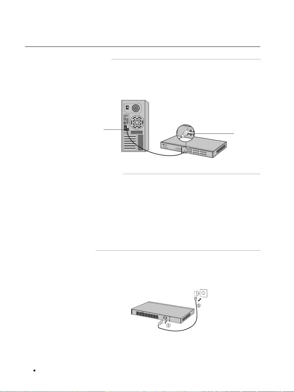
4.1 Ethernet Port
Connect a Ethernet port of the switch to the computer by RJ45 cable as the following
figure shows.
Figure 4-1 Connecting the RJ45 Port
RJ45 Port
RJ45 Cable
4.2 Verify Installation
After completing the installation, please verify the following items:
■
There are 5 to 10cm of clearance around the sides of the device for ventilation and the
air flow is adequate.
■
The voltage of the power supply meets the requirement of the input voltage of the device.
■
The power socket, device and rack are well grounded.
■
The device is correctly connected to other network devices.
4.3 Power On
Plug in the negative connector of the provided power cord into the power socket of the
device, and the positive connector into a power outlet as the following figure shows.
Figure 4-2 Connecting to Power Supply

10/100Mbps Unmanaged Switch
16Connection
Note:
The gure is to illustrate the application and principle. The power plug you get
from the package and the socket in your situation will comply with the regulation
in your country, so they may dier from the gure above.
4.4 Initialization
After the device is powered on, it begins the Power-On Self-Test. A series of tests
run automatically to ensure the device functions properly. During this time, its LED
indicators will respond as follows:
■
All of the LED indicators will flash momentarily for one second, which represents a
resetting of the system.
■
The Power LED indicator will light up.

10/100Mbps Unmanaged Switch
17 Appendix A Troubleshooting
Appendix A Troubleshooting
Q1.
Why is the Power LED is not lit?
The Power LED should be lit up when the power system works normally. If the Power LED
worked abnormally, please try the following:
1. Make sure that the power cable is connected properly, and the power contact is normal.
2. Make sure the voltage of the power supply meets the requirement of the input voltage of
the switch.
Q2.
Why is the Link/Act LED not lit while a device is connected to the corresponding
port?
Please try the following:
1. Make sure that the cable connectors are firmly plugged into the switch and the device.
2. Make sure the connected device is turned on and works normally.
3. Try to change the connected device’s transmission speed and duplex mode.
4. The cable must be less than 100 meters long (328 feet).

10/100Mbps Unmanaged Switch
18Appendix B Specications
Appendix B Specifications
Item Content
Standards
IEEE 802.3i 10Base-T
IEEE 802.3u 100Base-TX
IEEE 802.3x Flow Control
Transmission Medium
10Base-T: UTP/STP of Cat. 3 or above(maximum 100m)
100Base-TX: UTP/STP of Cat. 5 or above(maximum 100m)
Safety & Emissions FCC, CE
Transfer Method Store-and-Forward
MAC Address Learning Automatically learning, automatically aging
Frame Forward Rate
10Base-T: 14881pps/Port
100Base-Tx: 148810pps/Port
LEDs Power, Link/Act
Operating Temperature 0
℃
to 40
℃
(32℉ to 104℉)
Storage Temperature -40
℃
to 70
℃
(-40℉ to 158℉)
Operating Humidity 10% to 90%RH Non-condensing
Storage Humidity 5% to 90%RH Non-condensing

FCC STATEMENT
This equipment has been tested and found to comply with the limits for a Class A digital device,
pursuant to part 15 of the FCC Rules. These limits are designed to provide reasonable protection
against harmful interference when the equipment is operated in a commercial environment. This
equipment generates, uses, and can radiate radio frequency energy and, if not installed and used in
accordance with the instruction manual, may cause harmful interference to radio communications.
Operation of this equipment in a residential area is likely to cause harmful interference in which case
the user will be required to correct the interference at his own expense.
This device complies with part 15 of the FCC Rules. Operation is subject to the following two
conditions:
1) This device may not cause harmful interference.
2) This device must accept any interference received, including interference that may cause
undesired operation.
Any changes or modifications not expressly approved by the party responsible for compliance could
void the user’s authority to operate the equipment.
CE Mark Warning
This is a Class A product. In a domestic environment, this product may cause radio interference, in
which case the user may be required to take adequate measures.
Продукт сертифіковано згідно с правилами системи УкрСЕПРО на відповідність вимогам
нормативних документів та вимогам, що передбачені чинними законодавчими актами України.
Safety Information
• When product has power button, the power button is one of the way to shut off the product; when
there is no power button, the only way to completely shut off power is to disconnect the product
or the power adapter from the power source.
• Don’t disassemble the product, or make repairs yourself. You run the risk of electric shock and
voiding the limited warranty. If you need service, please contact us.
• Avoid water and wet locations.

The products of TP-Link partly contain software code developed by third parties, including software code subject
to the GNU General Public License (“GPL”). As applicable, the terms of the GPL and any information on obtaining
access to the respective GPL Code used in TP-Link products are available to you in GPL-Code-Centre under (http://
www.tp-link.com/en/support/gpl/). The respective programs are distributed WITHOUT ANY WARRANTY and are
subject to the copyrights of one or more authors. For details, see the GPL Code and other terms of the GPL.
© 2017 TP-Link
7106507344 REV13.0.1
For technical support and other information, please visit http://www.tp-link.com/support,
or simply scan the QR code.