Loading ...
Loading ...
Loading ...
14
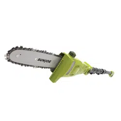
1. Rotate the chain saw head to the desired cutting angle
while pressing the rotating buttons located on both sides
simultaneously (Fig. 20).
2. Release the buttons when the chain saw head is set to the
desired angle.
NOTE: Failure to properly secure the chain saw head may
result in personal injury and/or property damage.
mWARNING! Always ensure the chain saw head is
securely locked! Do not attempt to use the pole chain saw with
the head in any other position or unlocked!
Adjusting the Auxiliary Handle
The chain saw is equipped with an auxiliary handle that can be
adjusted and removed. Follow the instruction below to operate
the auxiliary handle
mWARNING! Make sure the knob, bolt, and the screws
are xed into place. Failure to lock any of them as directed
could result in personal injury or property damage.
To Remove the Auxiliary Handle
1. Disconnect the saw from the power supply by removing
the battery from the compartment.
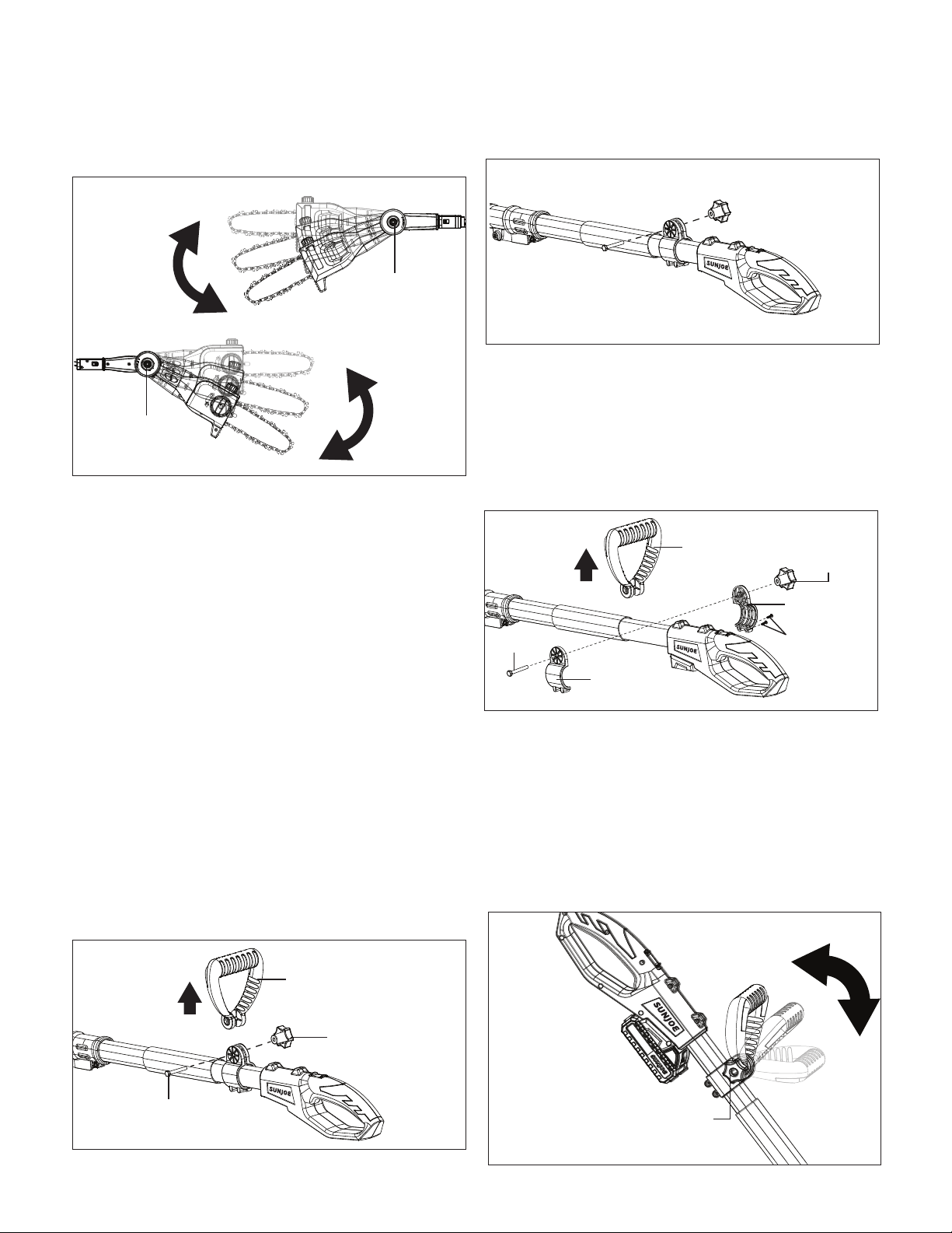
2. Unscrew the auxiliary handle lock knob and remove it and
the bolt, then the auxiliary handle can be pulled out
(Fig. 21).
3. Re-assemble the auxiliary handle lock knob and the bolt
on (Fig. 22).
To Adjust the Position of the Auxiliary Handle
1. Disconnect the saw from the power supply by removing
the battery from the compartment.
2. Remove the auxiliary handle lock knob, the bolt, and the
auxiliary handle. Use a screw driver to remove the two
screws that used to x the auxiliary handle loops.
Remove the loops from the pole (Fig. 23).
3. Re-assemble the auxiliary handle loop on the desired spot
on the pole by using the two screws, and put back the
auxiliary handle, the auxiliary handle lock knob and the
bolt (Fig. 23).
To Adjust the Angle of the Auxiliary Handle
1. Stop the saw by releasing the On/O switch.
2. The auxiliary handle can be adjusted in -45°, 0°, 45°.
Rotate the auxiliary handle lock knob to unlock the handle,
and then rotate the handle to the desired angle (Fig. 24).
Fig. 20
Rotating button
Front Side
Back Side
Rotating button
R
Fig. 21
Auxiliary handle
Auxiliary handle
lock knob
Bolt
R
Fig. 22
R
Fig. 23
Auxiliary handle
Auxiliary
handle
lock knob
Bolt
Auxiliary
handle loop
Screws
Auxiliary
handle loop
R
Fig. 24
Auxiliary handle
lock knob
Loading ...
Loading ...
Loading ...