
Loading ...
Loading ...
Loading ...
14. Scraper bar
15. Light switch
16. Headlights (2)
17. Discharge chute
18. Deector knob
19. Chute deector
20. Chute clean-out tool
21. Lower chute crank
22. Crank rod connector
23. Thumbscrew
24. Upper chute crank
25. Rubber ring
26. Upper frame
7
Unpacking
Carton Contents:
• Electric snow thrower with middle frame and upper frame
• Upper crank rod
• Chute cleaning tool
• Handle knobs and bolts (4 sets)
• Manuals with registration card
1. Carefully remove the electric snow thrower and check to
see that all of the above items are supplied.
2. Inspect the product carefully to make sure no breakage or
damage occurred during shipping. If you nd damaged or
missing parts, DO NOT return the unit to the store. Please
call the Snow Joe
®
+ Sun Joe
®
customer service center at
1-866-SNOWJOE (1-866-766-9563).
NOTE: Do not discard the shipping carton and packaging
material until you are ready to use your new electric snow
thrower. The packaging is made of recyclable materials.
Properly dispose of these materials in accordance with
local regulations or save the packaging for long-term
product storage.
IMPORTANT! The equipment and packaging material are
not toys. Do not let children play with plastic bags, foils,
or small parts. These items can be swallowed and pose a
suocation risk!
Assembly
m
WARNING! Inspect wiring, which, if damaged during
shipping, may cause serious bodily injury during equipment
use. If any damage is seen or suspected, do not assemble.
Instead, contact the Snow Joe
®
+ Sun Joe
®
customer service
center at 1-866-SNOWJOE (1-866-766-9563) for assistance.
Handle with care during assembly so that electrical wiring does
not become damaged.
Handle Frame Assembly
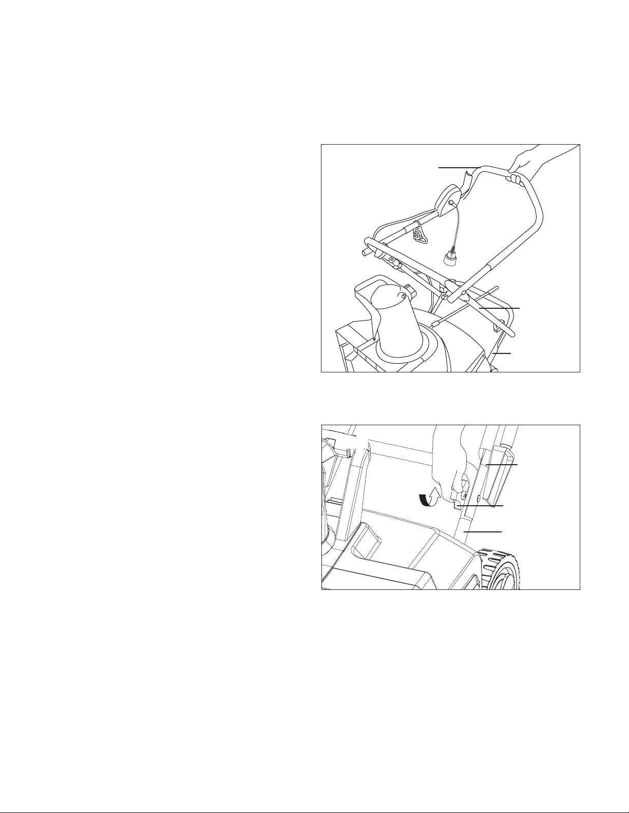
1. For easy assembly, the unit comes complete with
most parts already connected. To complete the handle
assembly, simply pull the middle frame back and pull the
upper frame up (Fig. 1).
2. Secure the connection of the middle frame to the lower
frame by fastening the rst set of knobs and bolts on each
side (Fig. 2).
3. Secure the connection of the upper frame to the middle
frame by fastening the second set knobs and bolts on
each side (Fig. 3).
Fig. 1
Upper
frame
Middle
frame
Lower
frame
Fig. 2
Lower frame
Middle
frame
Knob + bolt
Loading ...
Loading ...
Loading ...