Loading ...
Loading ...
Loading ...
96 PB
Wired Controller FSWC1 Owner's Manual
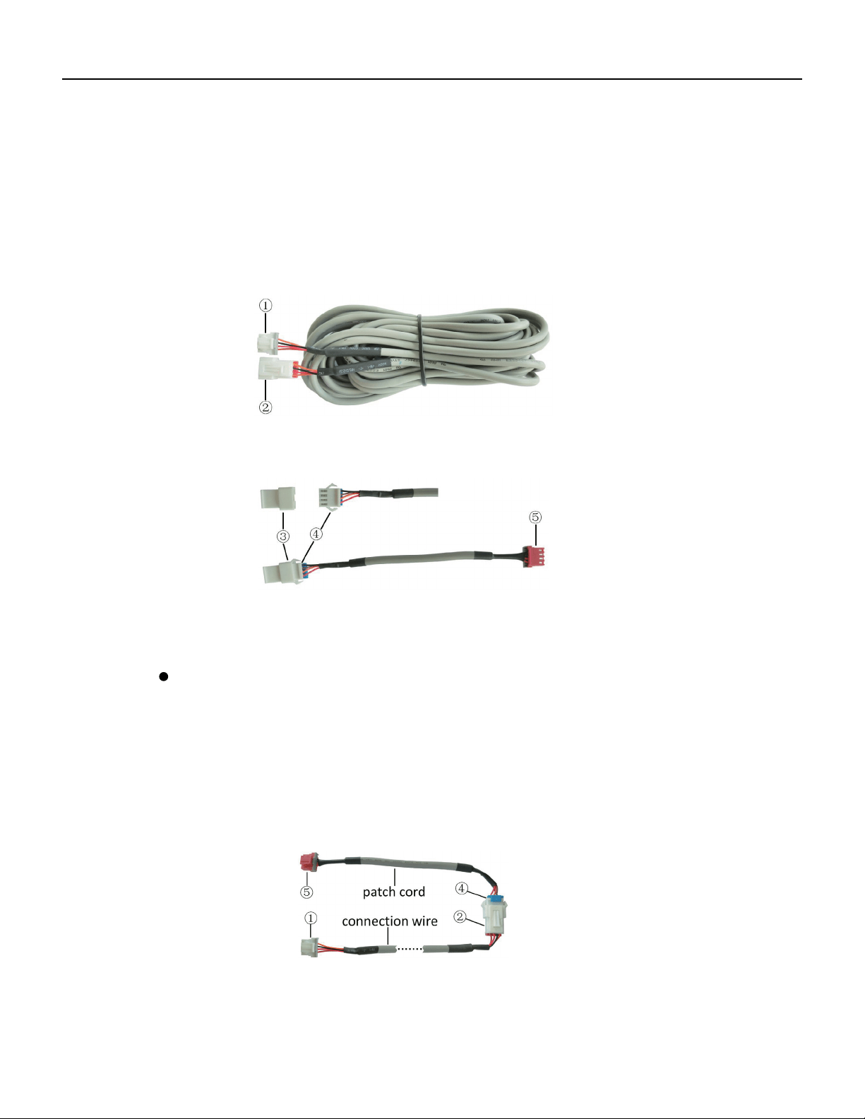
Fig. B: Schematic diagram of connection wire: Connect terminal ① with wired
controller CN2; connect terminal ② with the terminal ④ of patch cord
Only use the connection wire (fig. B) in the packing box of wired controller.
Connect the terminal ② to the terminal ④ of patch cord which has been installed
on the air conditioner; insert terminal ① to needle stand CN2 of wired controller.
If there’s protection terminal ③, pull out the protection terminal at first and then
install it.
Use the connection wire and patch cord in the packing box of wired controller.
Pull out the protection terminal of patch cord at first, connect the connection wire
with the patch cord according to fig. D, and then insert the terminal ① of connection
wire into the needle stand CN2 of wired controller and insert the terminal ⑤ of patch
cord into the terminal of wired controller of air conditioner as well.
25
Fig. C: Schematic diagram of patch cord: Terminal ③ is the protection terminal;
connect terminal ④ to the terminal ② of connection wire ;connect
terminal ⑤ to the terminal of wired controller of air conditioner
Fig. D: Schematic diagram after the connection wire and the patch cord have
been connected: connect the terminal ② of connection wire and the
terminal ④ of patch cord
If the air conditioner hasn’t been installed with the patch cord used for
connecting the wired controller.
WIRED CONTROLLER
Installation Instructions
Loading ...
Loading ...
Loading ...