Home
Bookmarks
Home
Friedrich
Friedrich FSHSR24A3A User Manual
Page 72
Friedrich FSHSR24A3A Single Zone Air Conditioning Outdoor Un
User Manual - Page 72
For FSHSR24A3A.
PDF File Manual
,
171 pages
,
Read Online
|
Download pdf file
INTRODUCTION
Important Safety Information
Personal injury or death hazards
Model identification guide
Indoor Units
Outdoor Units
Remote Control
SPECIFICATIONS
Product Specifications
Capacities and selection data
9-12K Operation Characteristics curve
18-24kK Operation Characteristics curve
36K Operation Characteristics curve
9-12K Capacity Variation Ratio According to Temperature
18-24 K Capacity Variation Ratio According to Temperature
36 K Capacity Variation Ratio According to Temperature
9-12K Noise Curve
18-24K Noise Curve
36 K Noise Curve
Cooling Data Sheet in Rated Frequency
Heating Data Sheet in Rated Frequency
18-24K Indoor Unit Dimensions
9-12K Outdoor Unit Dimensions
18-24K Outdoor Unit Dimensions
36 K Outdoor Unit Dimensions
OPERATION
Remote Control Button Identification
Remote Control Description
9-24k Sequence of Operation
36k Sequence of Operation
9-12K Refrigerant System Diagram
18-24K Refrigerant System Diagram
36 K Refrigerant System Diagram
INSTALLATION
Installation Tools
Installation Parts Checklist
Selection of Installation Location
Installation of Indoor Unit
Leak Check, Evacuation, and Charging (Triple Evacuation)
Checklist and Operation Test
Check Unit following Installation
Test Operation
REMOVAL
Indoor Unit
Outdoor Unit
WIRED CONTROLLER
Display
Buttons
Operation Instructions
Installation Instructions
R-410A SEALED SYSTEM REPAIR
Service Valves Appearance
Pumping Down
Gas Charging (After Repair)
COMPONENTS TESTING
Resistance Table of Ambient Temperature Sensor for Indoor and Outdoor Units (15kΩ)
Resistance Table of Ambient Temperature Sensor for Indoor and Outdoor Units (20kΩ)
Resistance Table of Ambient Temperature Sensor for Indoor and Outdoor Units (50kΩ)
9-12k Indoor Unit Printed Circuit Board Identification
18-24k Indoor Unit Printed Circuit Board Identification
36k Indoor Unit Printed Circuit Board Identification
9-12k Outdoor Unit Printed Circuit Board Identification
18-24k Outdoor Unit Printed Circuit Board Identification
36k Outdoor Unit Printed Circuit Board Identification
TROUBLESHOOTING
Diagnostic Codes
Malfunction of Temperature Sensor F1, F2
9-12k Malfunction of blocked Protection of IDU Fan Motor H6
18-36k Malfunction of blocked Protection of IDU Fan Motor H6
Malfunction of Protection of Jumper Cap C5
Malfunction of IDU Fan Motor U8
Malfunction of Communication E6
Malfunction of Power Supply from Indoor to Outdoor Unit
Malfunction of Detecting Plate (WIFI) JF
Indoor fan does not rotate and there is no Feedback
Temperature sensor malfunction
Malfunction diagnosis of startup failure
Diagnosis of losing synchronism for compressor
9-12k, 36k Diagnosis of overload and discharge malfunction
18-24k Diagnosis of overload and discharge malfunction
Capacity Charging malfunction - Outdoor unit
9-24k PM protection, phase current overcurrent
36k IPM Protection, Out-of-Step Fault, Compressor Phase Overcurrent
High temperature and Overload Protection Diagnosis
PFC (Correction Power Factor) Outdor Unit Malfuction
Communication malfunction: (following AP1 for outdoor unit control board)
High-pressure Protection
Troubleshooting for Malfunction without Active Error Code
WIRING DIAGRAMS
9-12K Indoor Unit Wiring Diagram
18-24k Indoor Unit Wiring Diagram
36K Indoor Unit Wiring Diagrams
18-24k Outdoor Unit Wiring Diagrams
36k Outdoor Unit Wiring Diagrams
PARTS CATALOG
9 K Indoor Unit
12k Indoor Unit
18 K Indoor Unit
24 K Indoor Unit
36 K Indoor Unit
9 K Outdoor Unit
12k Outdoor Unit
18k Outdoor Unit
24k Outdoor Unit
36k Outdoor Unit
APPENDIX
Appendix 1: Reference Sheet of Celsius and Farenheit
Appendix 2: Configuration of Connection Pipe
Appendix 3: Pipe Expanding Method
LIMITED WARRANTY
FRIEDRICH AUTHORIZED PARTS DEPOTS
Page 72/171
Page 1
Page 2
Page 3
Page 4
Page 5
Page 6
Page 7
Page 8
Page 9
Page 10
Page 11
Page 12
Page 13
Page 14
Page 15
Page 16
Page 17
Page 18
Page 19
Page 20
Page 21
Page 22
Page 23
Page 24
Page 25
Page 26
Page 27
Page 28
Page 29
Page 30
Page 31
Page 32
Page 33
Page 34
Page 35
Page 36
Page 37
Page 38
Page 39
Page 40
Page 41
Page 42
Page 43
Page 44
Page 45
Page 46
Page 47
Page 48
Page 49
Page 50
Page 51
Page 52
Page 53
Page 54
Page 55
Page 56
Page 57
Page 58
Page 59
Page 60
Page 61
Page 62
Page 63
Page 64
Page 65
Page 66
Page 67
Page 68
Page 69
Page 70
Page 71
Page 72
Page 73
Page 74
Page 75
Page 76
Page 77
Page 78
Page 79
Page 80
Page 81
Page 82
Page 83
Page 84
Page 85
Page 86
Page 87
Page 88
Page 89
Page 90
Page 91
Page 92
Page 93
Page 94
Page 95
Page 96
Page 97
Page 98
Page 99
Page 100
Page 101
Page 102
Page 103
Page 104
Page 105
Page 106
Page 107
Page 108
Page 109
Page 110
Page 111
Page 112
Page 113
Page 114
Page 115
Page 116
Page 117
Page 118
Page 119
Page 120
Page 121
Page 122
Page 123
Page 124
Page 125
Page 126
Page 127
Page 128
Page 129
Page 130
Page 131
Page 132
Page 133
Page 134
Page 135
Page 136
Page 137
Page 138
Page 139
Page 140
Page 141
Page 142
Page 143
Page 144
Page 145
Page 146
Page 147
Page 148
Page 149
Page 150
Page 151
Page 152
Page 153
Page 154
Page 155
Page 156
Page 157
Page 158
Page 159
Page 160
Page 161
Page 162
Page 163
Page 164
Page 165
Page 166
Page 167
Page 168
Page 169
Page 170
Page 171
Contents
Table of Contents
Search
Previous
Next
Troubleshooting
Bookmarks
Loading ...
Loading ...
Loading ...
72
PB
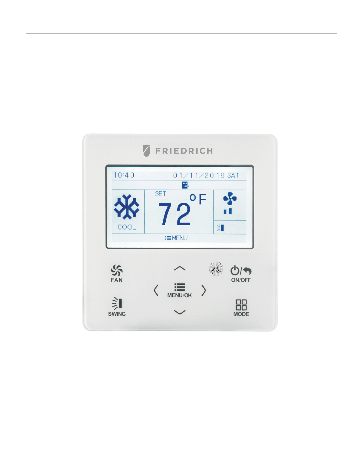
WIRED CONTROLLER
Displ
ay
Loading ...
Loading ...
Loading ...
File type: PDF
File name: 9196451_fshsr09a1a.pdf
File size: 30.22 MB
File Language: English
Pages: 171
Author: Friedrich
Published:
2021-11-14
Updated: 2023-05-16
Download File
Table of Contents
×
INTRODUCTION
4
Important Safety Information
4
Personal injury or death hazards
6
Model identification guide
7
Indoor Units
8
Outdoor Units
9
Remote Control
9
SPECIFICATIONS
10
Product Specifications
10
Capacities and selection data
14
9-12K Operation Characteristics curve
18
18-24kK Operation Characteristics curve
18
36K Operation Characteristics curve
19
9-12K Capacity Variation Ratio According to Temperature
20
18-24 K Capacity Variation Ratio According to Temperature
20
36 K Capacity Variation Ratio According to Temperature
21
9-12K Noise Curve
21
18-24K Noise Curve
22
36 K Noise Curve
22
Cooling Data Sheet in Rated Frequency
23
Heating Data Sheet in Rated Frequency
23
18-24K Indoor Unit Dimensions
25
9-12K Outdoor Unit Dimensions
26
18-24K Outdoor Unit Dimensions
27
36 K Outdoor Unit Dimensions
27
OPERATION
28
Remote Control Button Identification
28
Remote Control Description
29
9-24k Sequence of Operation
33
36k Sequence of Operation
42
9-12K Refrigerant System Diagram
45
18-24K Refrigerant System Diagram
45
36 K Refrigerant System Diagram
46
INSTALLATION
47
Installation Tools
48
Installation Parts Checklist
51
Selection of Installation Location
51
Installation of Indoor Unit
53
Leak Check, Evacuation, and Charging (Triple Evacuation)
60
Checklist and Operation Test
62
Check Unit following Installation
62
Test Operation
62
REMOVAL
63
Indoor Unit
63
Outdoor Unit
68
WIRED CONTROLLER
72
Display
72
Buttons
74
Operation Instructions
75
Installation Instructions
93
R-410A SEALED SYSTEM REPAIR
98
Service Valves Appearance
98
Pumping Down
99
Gas Charging (After Repair)
100
COMPONENTS TESTING
101
Resistance Table of Ambient Temperature Sensor for Indoor and Outdoor Units (15kΩ)
101
Resistance Table of Ambient Temperature Sensor for Indoor and Outdoor Units (20kΩ)
102
Resistance Table of Ambient Temperature Sensor for Indoor and Outdoor Units (50kΩ)
103
9-12k Indoor Unit Printed Circuit Board Identification
104
18-24k Indoor Unit Printed Circuit Board Identification
105
36k Indoor Unit Printed Circuit Board Identification
106
9-12k Outdoor Unit Printed Circuit Board Identification
107
18-24k Outdoor Unit Printed Circuit Board Identification
108
36k Outdoor Unit Printed Circuit Board Identification
109
TROUBLESHOOTING
110
Diagnostic Codes
110
Malfunction of Temperature Sensor F1, F2
118
9-12k Malfunction of blocked Protection of IDU Fan Motor H6
119
18-36k Malfunction of blocked Protection of IDU Fan Motor H6
120
Malfunction of Protection of Jumper Cap C5
121
Malfunction of IDU Fan Motor U8
122
Malfunction of Communication E6
124
Malfunction of Power Supply from Indoor to Outdoor Unit
125
Malfunction of Detecting Plate (WIFI) JF
126
Indoor fan does not rotate and there is no Feedback
127
Temperature sensor malfunction
128
Malfunction diagnosis of startup failure
129
Diagnosis of losing synchronism for compressor
130
9-12k, 36k Diagnosis of overload and discharge malfunction
131
18-24k Diagnosis of overload and discharge malfunction
132
Capacity Charging malfunction - Outdoor unit
133
9-24k PM protection, phase current overcurrent
134
36k IPM Protection, Out-of-Step Fault, Compressor Phase Overcurrent
135
High temperature and Overload Protection Diagnosis
136
PFC (Correction Power Factor) Outdor Unit Malfuction
137
Communication malfunction: (following AP1 for outdoor unit control board)
138
High-pressure Protection
139
Troubleshooting for Malfunction without Active Error Code
140
WIRING DIAGRAMS
143
9-12K Indoor Unit Wiring Diagram
143
18-24k Indoor Unit Wiring Diagram
144
36K Indoor Unit Wiring Diagrams
145
18-24k Outdoor Unit Wiring Diagrams
147
36k Outdoor Unit Wiring Diagrams
147
PARTS CATALOG
148
9 K Indoor Unit
148
12k Indoor Unit
150
18 K Indoor Unit
152
24 K Indoor Unit
154
36 K Indoor Unit
156
9 K Outdoor Unit
158
12k Outdoor Unit
160
18k Outdoor Unit
162
24k Outdoor Unit
164
36k Outdoor Unit
166
APPENDIX
168
Appendix 1: Reference Sheet of Celsius and Farenheit
168
Appendix 2: Configuration of Connection Pipe
168
Appendix 3: Pipe Expanding Method
169
LIMITED WARRANTY
170
FRIEDRICH AUTHORIZED PARTS DEPOTS
171
Search:
×
Search