Loading ...
Loading ...
Loading ...
Installation Guide • 17
Installation and Operation
PRO.BOSE.COM
EX-4ML and EX-8ML Connections
Audio Wiring
The EX-4ML and EX-8ML endpoints include four (4) or eight (8) balanced, mic/line analog audio inputs,
respectively. Connect devices to these inputs using the included 3.81 mm, 7-pin Euroblock connectors.
Control Wiring
Each analog audio input includes control connections for two general purpose outputs (GPO) and one
general purpose input (GPI). The GPIO are compatible with most microphones that use LEDs or LED
rings and integrated push buttons.
The EX-4ML and EX-8ML also include 12 V microphone power output on each audio connector, which
can power microphones with LEDs and eliminate the need for an external power supply.
Microphones can be wired directly by following the wiring diagrams shown below. For some
microphones, an accessory adapter may be available to simplify the wiring.
Note: The following diagrams are provided for convenience, but are subject to change. Please review
wiring information from the microphone manufacturer for the most up-to-date information.
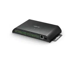
Shure MX41x
Mic Signal Mic Wire
Color
Function EX UTB
Connector
Pin
Audio + Red Audio + +
Audio - Black Audio - -
Shield Bare Shield
Logic Ground Green Ground
Switch Out White Switch I1
LED In Orange LED O1
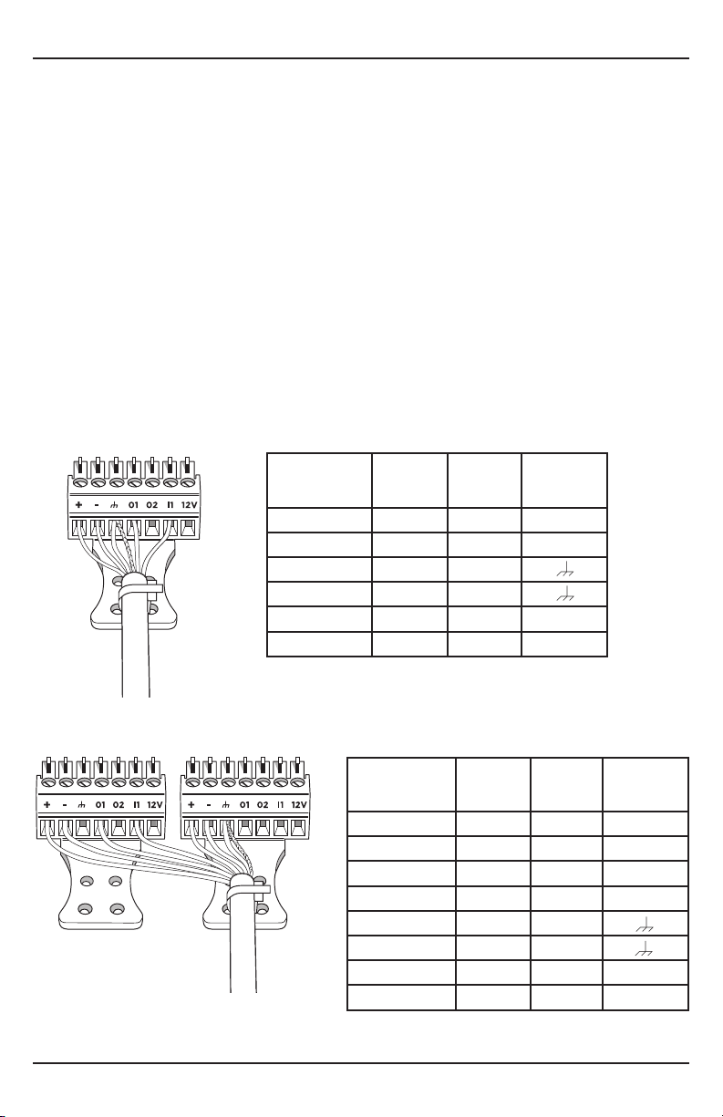
Shure MX396/Dual
Mic Signal Mic Wire
Color
Function EX UTB
Connector
Pin
Mic 1 Audio + White Audio + Ch 1 +
Mic 1 Audio - Green Audio - Ch 1 -
Mic 2 Audio + Orange Audio + Ch 2 +
Mic 2 Audio - Blue Audio - Ch 2 -
Shield Bare Shield
Logic Ground Silver Ground
Switch Out Red Switch Ch 1 I1
LED In Black LED Ch 1 O1
Loading ...
Loading ...
Loading ...