Loading ...
Loading ...
Loading ...
Installation Guide • 13
Installation and Operation
PRO.BOSE.COM
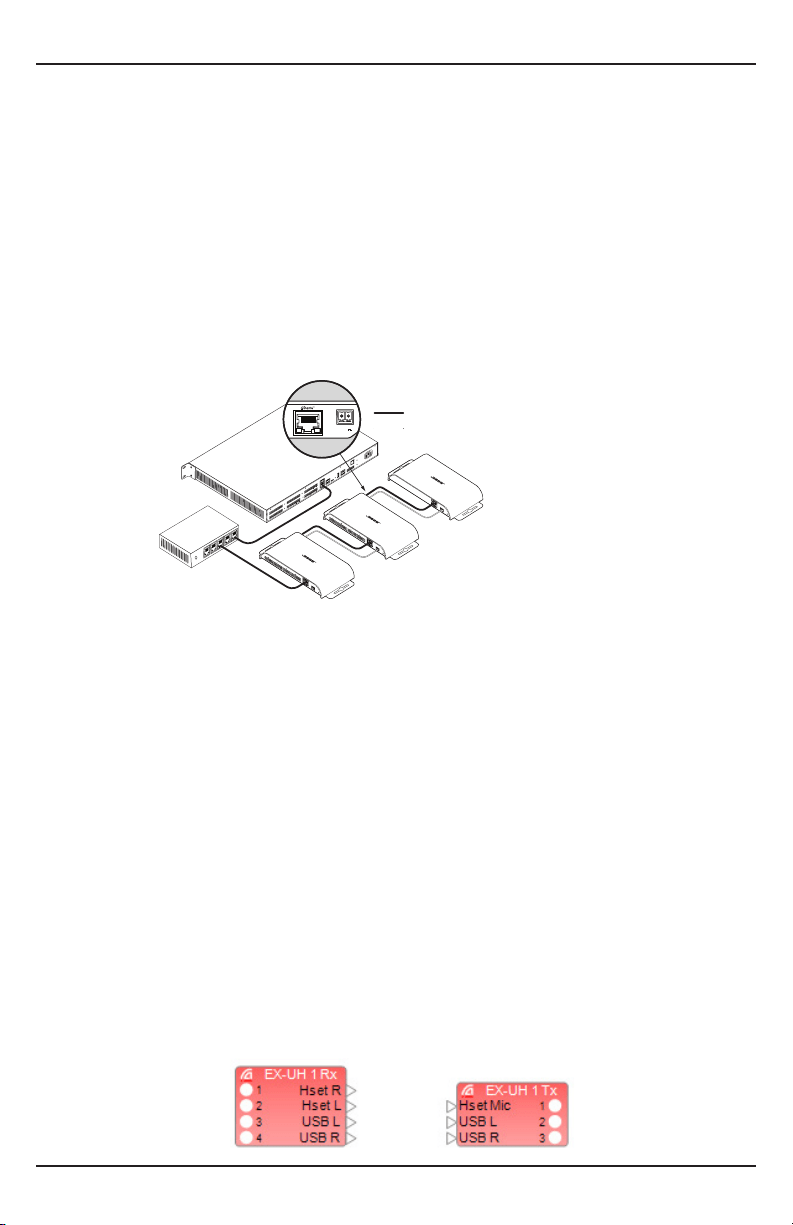
Connecting Multiple Endpoints
Daisy-chain a maximum of three (3) endpoints using PoE+, or up to six (6) endpoints using an external
power supply.
To connect multiple endpoints:
1. Connect a port on the Dante network switch to the Dante/PoE+ port on the first endpoint in the
chain using a Cat 5 cable. If you are using PoE+ to power the endpoints, connect to a PoE+ enabled
port on the Dante network switch.
2. Connect the Dante port on the first endpoint to the Dante/PoE+ port on the second endpoint, using
a Cat 5 cable. If you are not using PoE+ to power the endpoints, connect an external power supply to
the first endpoint.
3. Connect the +12 V DC OUT on the first endpoint to the +12 V DC IN on the second endpoint.
Terminate each end of this cable using the included 2-pin Euroblock connectors.
Repeat steps 2 and 3 for each additional endpoint.
IN 1 IN 2 IN 3
IN 4
OUT 1 OUT 2
OUT 3 OUT 4
IN 5
IN 6
IN 7
IN 8
OUT 5 OUT 6 OUT 7 OUT 8
IN 9
1 23
4
5
1 23 4
5
IN 10 IN 11 IN 12
ControlSpace
ControlSpace
EX-1280C
Conferencing Signal Processor
VoIP
USB
USB
AmpLink
SERIAL
PSTN
100-240V~50/60Hz 60WMAX
TxRx A
B
CC-16
CONTROL INPUTS
CONTROL OUTPUTS
+
-
+
-
+
-
+
-
+24V
+
-
OUT
+24V
+
-
OUT
CH 1
I112V O2 O1
CH 2CH 3CH 4
+12V ±
OUT
-
+
I112V
O2O1
-
+
I112V O2 O1
-
+
I1
12V
O2
O1
-
+
CH 1
I1
12V O2
O1
CH 2CH 3CH 4
+12V ±
OUT
-
+
I112V
O2O1
-
+
I112V O2 O1
-
+
I1
12V O2 O1
-
+
+12V ±
OUT
Network Configuration
Network Connections
Each EX Dante Endpoint has two (2) Dante ports, which facilitates daisy-chaining: Additional endpoints
can be connected to the first, eliminating the need for additional home-runs. Note that PoE+ power is
not daisy-chained; therefore, when daisy-chaining, the additional devices must be powered either by
connecting to the previous devices’ +12 V DC OUT or by using the optional EX Endpoint Power Supply
accessory.
The two Dante ports on each endpoint are connected via an internal Ethernet switch. Therefore, either
one can be used to provide the Dante connection. However, if PoE+ is used to power the endpoint, then
the cable must be connected to the Dante/PoE+ port.
Network Communications
EX-UH
The EX-UH has two (2) USB inputs (USB L, USB R) and two (2) analog inputs (Hset L, Hset R). It also has
two (2) USB outputs (USB L, USB R) and one (1) analog output (Hset Mic). The USB and analog IO are
transmitted or received over Dante; thus, the EX-UH appears as a 4-input, 3-output device in the Bose
ControlSpace Designer software and the Dante controller software. ControlSpace Designer supports
“Auto Dante Programming” for the EX-UH, eliminating the need to use the PC to configure the audio
routing.
When an EX-UH is added to a design, and then to a particular DSP, it will show up as “Dante Audio
Routes” for that DSP (4 Rx ch and 3 Tx ch):
ControlSpace
EX-1280C
Dante PoE+
Network Switch
EX-UH
Cat 5 (Network & PoE)
2-conductor, 20 AWG
EX-4ML
EX-8ML
Loading ...
Loading ...
Loading ...