USER’S GUIDE
Version: FM12-201705RM
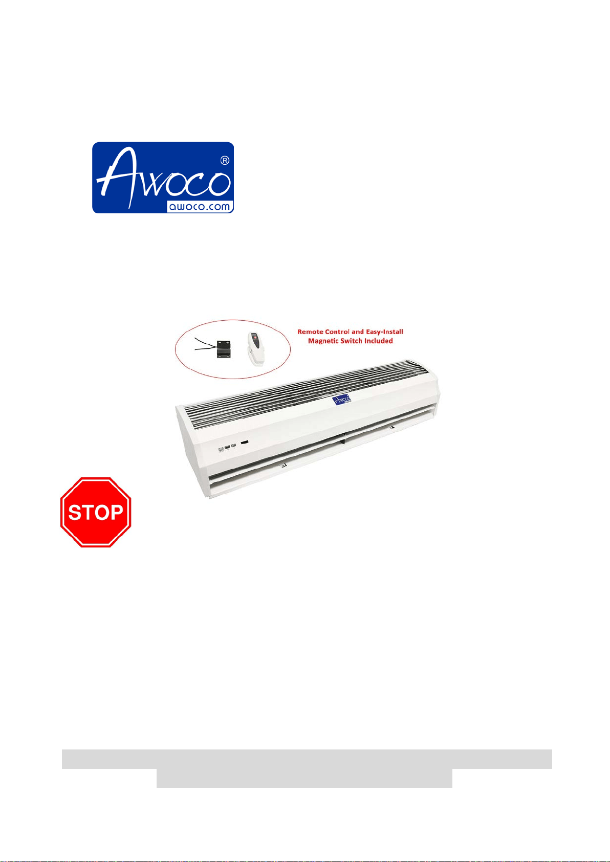
AIR CURTAINS
Models: FM-1209T, FM-1210T,
FM-1212T, FM-1215T
(2 Speeds with Remote Control & Magnetic Switch)
STOP and Read! Test before installing
1. Do NOT plug in power cord to power source, use a screw driver to rotate
the fan blades.
2. If the fan doesn’t rotate smoothly, remove the front cover screws and
open the front cover.
3. Reseat the fan blade bearings and align the motor to fix the issues. Then
replace the front cover back with tighten the screws.
4. Plug in 110V-120V power source; press the switch to H or L to test it. If
the air curtain works normally, refer to section 3 through 7 to install the
air curtain. Refer to section 10 for technical support.
PLEASE READ AND SAVE THESE INSTRUCTIONS.
Strongly recommend to test the unit before installation for any
defective or damage during shipment.

1
WARNING – TO REDUCE THE RISK OF FIRE, ELECTRIC SHOCK, OR INJURY
TO PERSONS, READ THE FOLLOWING CAREFULLY before attempting to
assemble, install, operate or maintain the product.
A. Always disconnect, lock and tag power source before installing or servicing product.
Failure to disconnect power source can result in fire, shock or serious injury.
B. Installation work and electrical wiring must be done by qualified pers
on(s) in
accordance with all applicable codes and standards, including fire-rated construction.
C. When cutting or drilling into wall or ceiling, do not damage electrical wiring and other
hidden utilities.
D. To reduce the risk of fire or electric shock, do not use this fan with any solid-state
speed control device
E. Repair and maintenance operations can only be performed by qualified personnel.
F.
Verify and ensure the rated voltage and frequency (please refer to the rating label) of
the air curtain is in compliance with the mains supply.
CONTENTS
1. PRODUCT INTRODUCTIONS ................................................................................................ 1
2. INSTALLATION DIMENSIONS ................................................................................................ 2
3. INSTALLATION PLANNING & CAUTIONS ............................................................................. 3
4. INSTALLATION INSTRUCTIONS............................................................................................ 4
5. TECHNICAL PARAMETER ..................................................................................................... 5
6. WIRING DIAGRAM ................................................................................................................. 6
7. OPTIONAL MAGNETIC SWITCH INSTALLATION ................................................................. 6
8. OPERATING INSTRUCTIONS ................................................................................................ 7
9. MAINTENANCE AND CLEANING ........................................................................................... 7
10. SUPPORT AND CONTACT ................................................................................................. 7
1. PRODUCT INTRODUCTIONS
Air curtains are widely installed at the entrances of supermarket, theater, meeting room, hotel,
office room, storage room etc. They can reduce penetration of insects, outside dust,
unconditioned air into a conditioned space by forcing an air stream over the entire entrance to
create a comfortable environment for you.
2
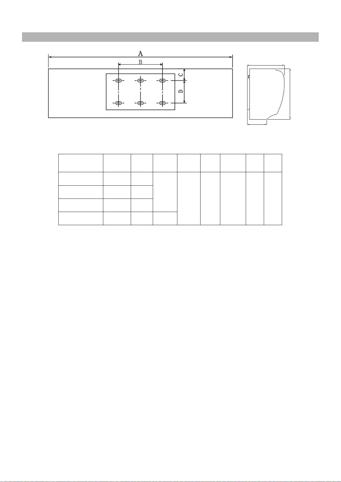
2. INSTALLATION DIMENSIONS
F
G
E
UNIT: inch
MODEL
Max
Entry
Opening
A B C D E F G
FM-1209T
38 35.43
17.32
1.65 3.54 7.48 4.13 8.86
FM-1210T
42 39.37
FM-1212T
50 47.24
FM-1215T
62 59.06 33.07
Note: the data are subjected to change without notice due to product development.
3
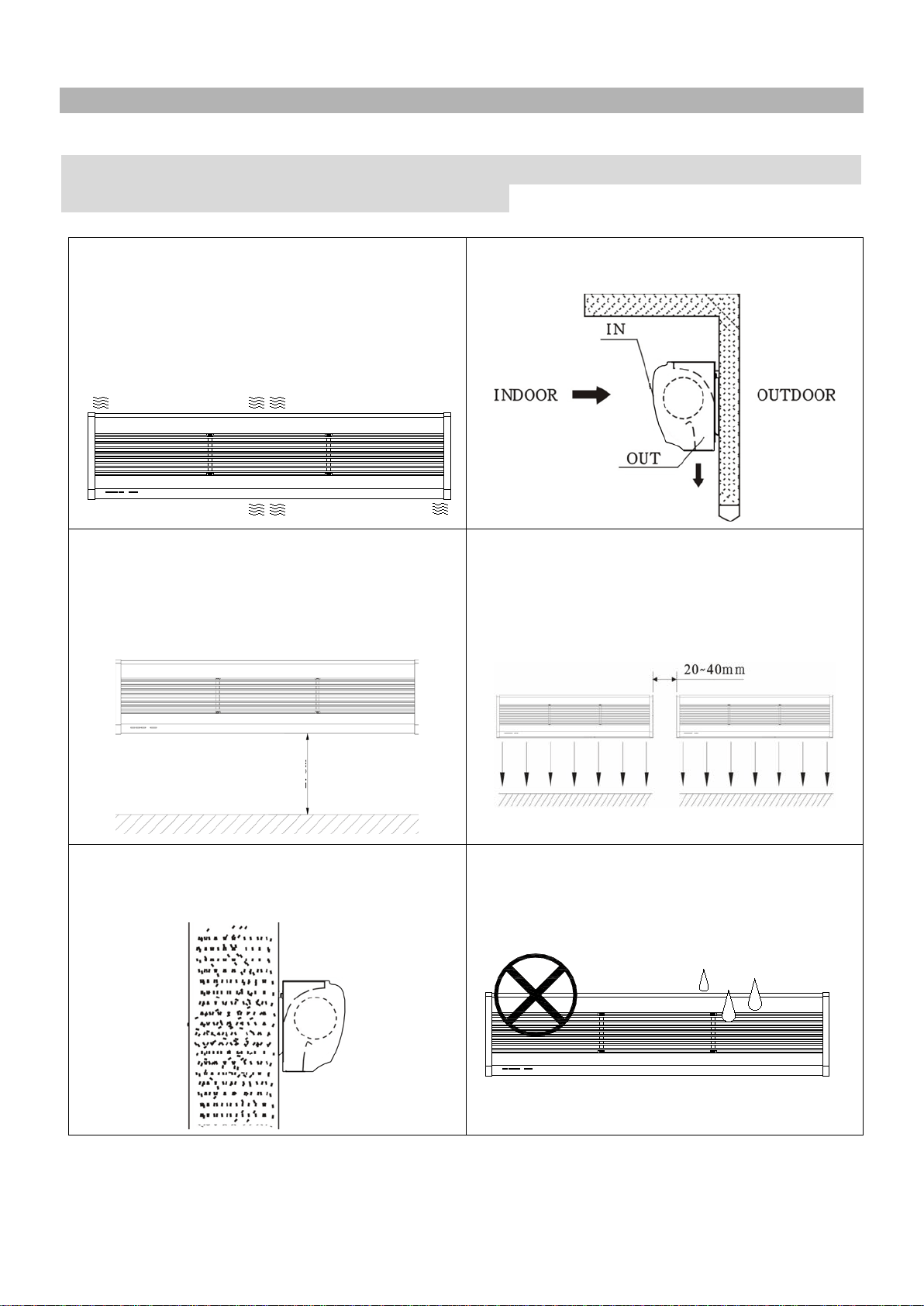
3. INSTALLATION PLANNING & CAUTIONS
Must observe the following when installing air curtains:
Strongly recommend to test the unit before installation for any
defective or damage during shipment.
3.1 Please install the unit on a sturdy
supporting structure to avoid
shaking and
ensure its security (because the unit running
may cause the wall to become loose or
shake and make noise).
3.2 Please install the unit inside the room.
3.3 Install the unit between 7 feet to 8 feet
from the ground.
ATENCIÓN
:
Instalar la unidad entre los 7
a 8 pies desde del suelo.
3.4 When the entrance is wider than the
unit, it is recommended to install two or
more units in parallel. In this case, provide
20-40mm gaps between the units.
3.5 Don’t allow gaps between the unit and
the wall.
3.6 Don’t install the unit at a place where it
is splashed by water, exposed to excessive
steam, dust / explosive gas or corrosive
gas.
7’ – 8’
4
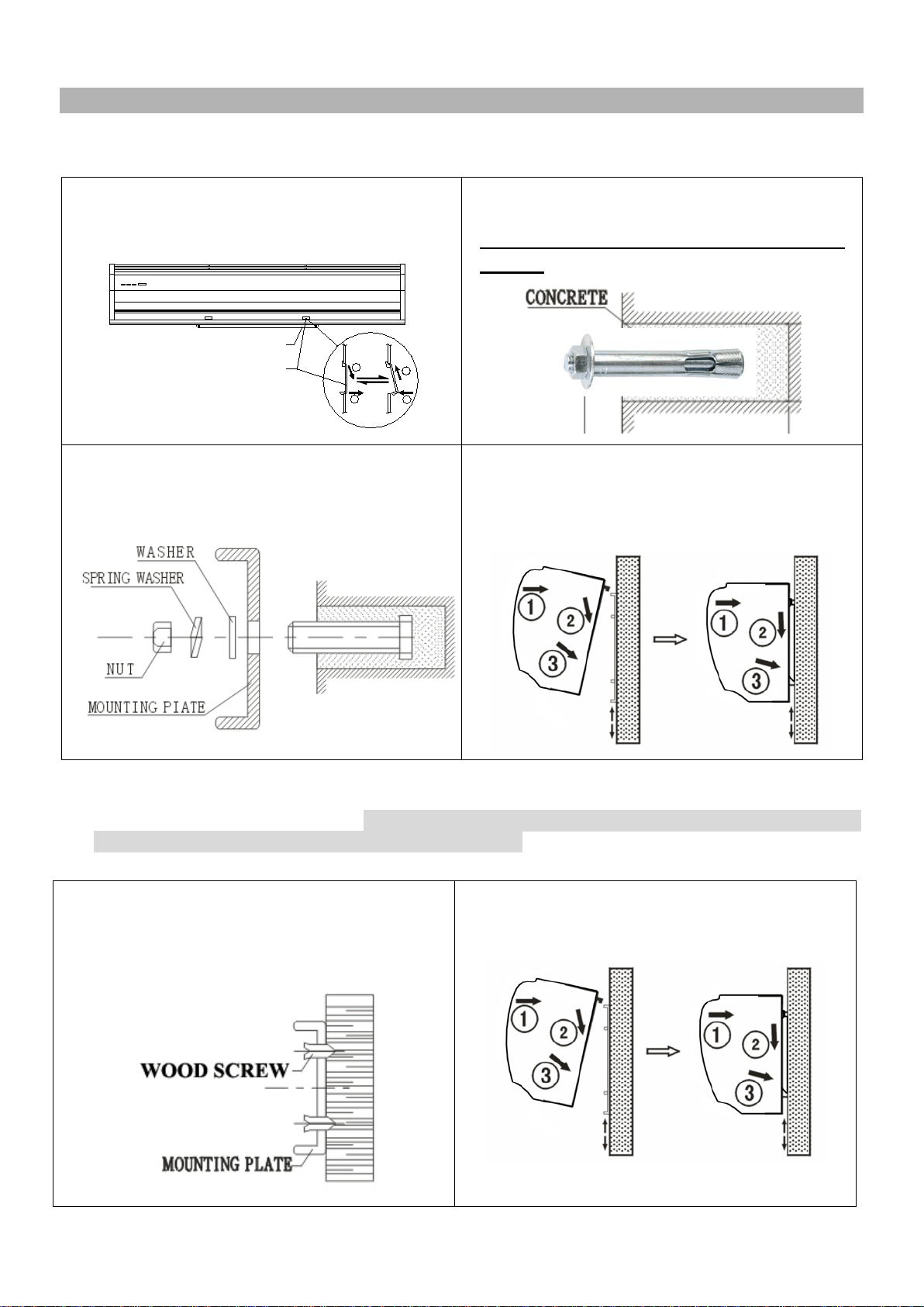
4. INSTALLATION INSTRUCTIONS
A. Installing on the concrete wall:
4.1.1 Remove the plastic parts, unscrew the
fixing screws to remove the mounting plate
from the back of the main body.
PLASTIC PARTS
1
2
MOUNTING PLATE
2
1
4.1.2 Determine the mounting location with
the mounting plate. Drill holes and insert the
Zinc-Plated Steel Hex-Nut-Head Sleeve
Anchor (not included).
4.1.3 Tighten the nuts to secure the
mounting plate to the wall (use the washers
and nuts as the Fig shows).
4.1.4 Hang the main body onto the upper
end of the mounting plate, and then tighten
the bottom fixing screws back
to the
mounting plate.
B. Installing on the wooden wall: (Note: make sure the screws are secured in the wood,
attach an extra wood frame to the wall if needed.)
4.2.1 Refer to step 4.1.1 and determine the
mounting location, then securely mount the
mounting plate to the wooden wall with tapping
screws.
4.2.2 Hang the main body onto the upper end
of the mounting plate, and then tie the bottom
fixing screws back to the mounting plate.
5
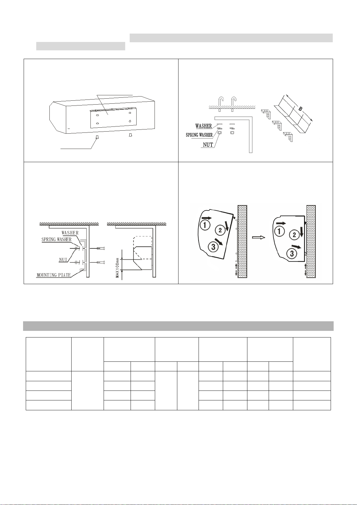
C. Installing from the ceiling: (Note: this installation is NOT recommended; the ceiling
brackets are not supplied.)
4.3.1 Remove the mounting plate from the main
body as per the step 4.1.1
MOUNTING PIATE
FIXING SCREW
4.3.2 Securely mount the ceiling brackets (not
included) as the Fig shows.
4.3.3 Set the mounting plate to the ceiling
brackets and tighten it securely as the Fig
shows. The position of the mounting plate can
be adjusted in vertical direction
according to
need, but the max distance is 100mm.
4.3.4 Hang the main body onto the upper end
of the mounting plate, and then tie the bottom
fixing screws back to the mounting plate.
5. TECHNICAL PARAMETER
Model
No.
Voltage
(V~Hz)
Power
(W)
Max air
velocity
(FPM)
Air volume
(CFM)
Noise level
(dB)
Net weight
(Lb)
H L H L H L H L
FM-1209T
120V,
60Hz
140 90
2165 1772
1112 874 57 55 22.0
FM-1210T 190
140
1271 1033 58 56 24.3
FM-1212T
200
150
1510
1271
58
56
27.6
FM-1215T
250
200
1986
1589
59
57
33.1
Note: the data are subjected to change without notice due to product development.
6
6. WIRING DIAGRAM
WHITE
DOUBLE SPEED INFRARED REMOTE CONTROLLED WIRING DIAGRAM
BLUE(BROWN/RED)
THERMAL CUT-OUT
RECEIVER
YELLOW
BLACK
WHITE
GREEN
ORANGE
(YELLOW)
C
I/C
I/O
RECEIVER
BROWN
GREY
BLUE
N
L
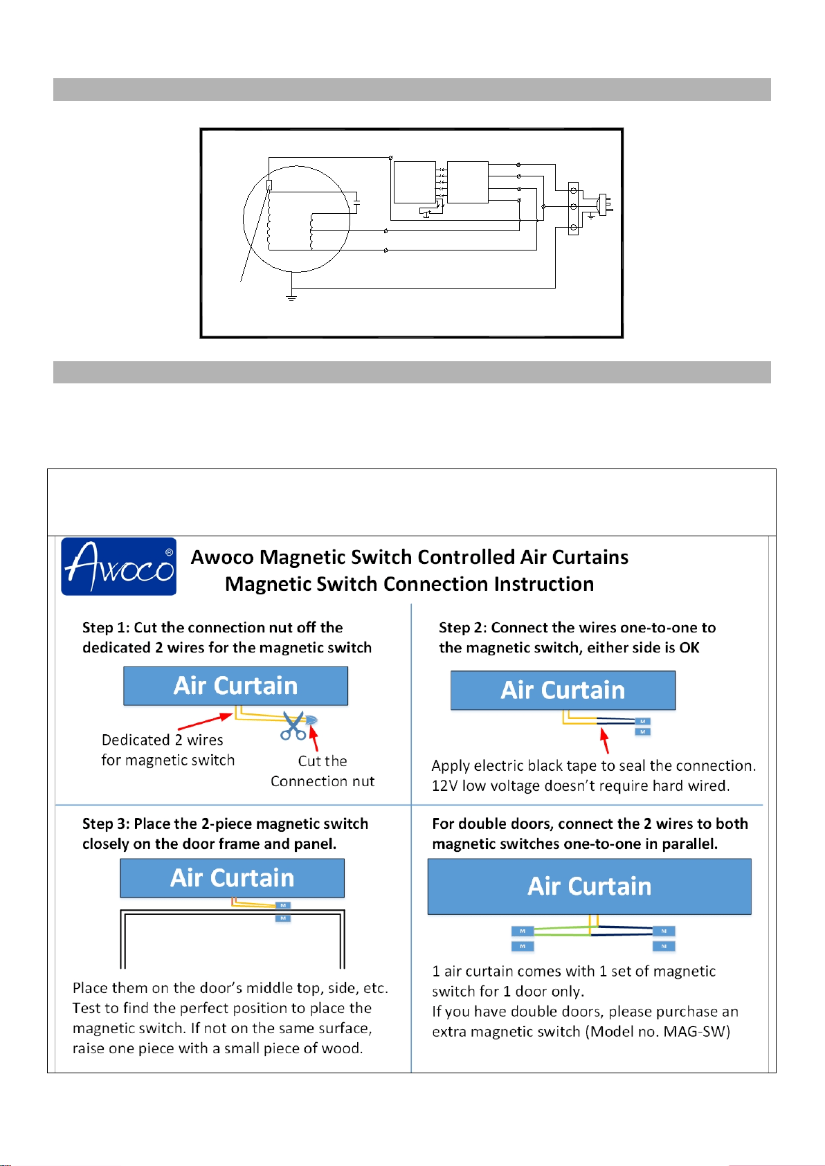
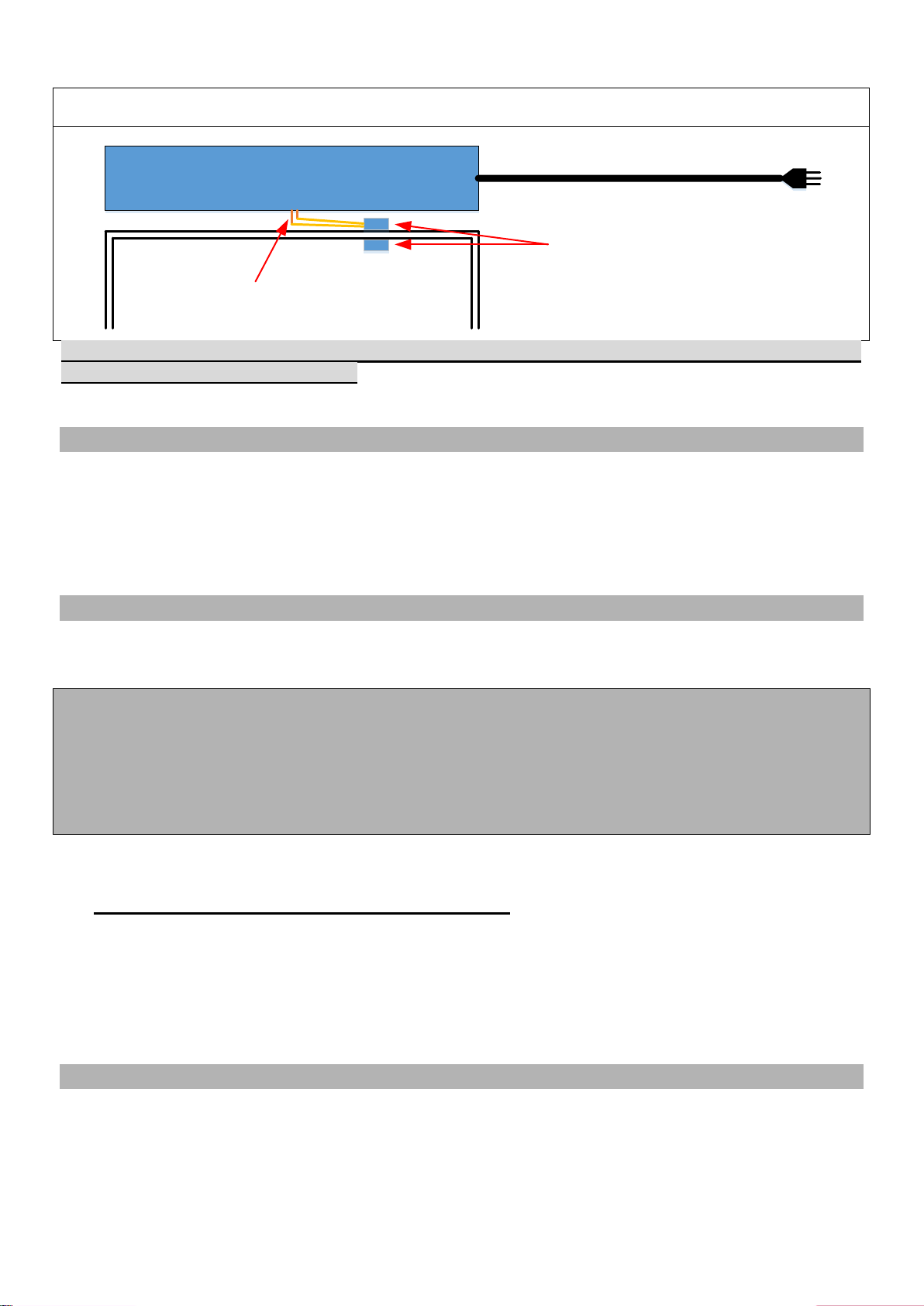
7. OPTIONAL MAGNETIC SWITCH INSTALLATION
This air curtain comes with a magnetic door switch, contact seller or Awoco if you are missing a
magnetic switch. The dedicated 2 wires (Yellow) are to connect to the magnetic switch.
Note: Keep the 2 wires connected (closed) if the magnetic switch is not used.
Connect the magnetic door switch:
Cut the dedicated 2 wires’ nut, and connect the wires to the magnetic switch’s 2 wires. Use the black electrical
tape to seal the connection.
7
Install the 2 pieces magnetic switch to the door/window edge and frame; keep them close when the
door/window is closed. Hard wiring to 12V low voltage magnetic switch is NOT needed.
Air Curtain
Dedicated 2 wires (12V DC) for
the magnetic switch
M
M
Install the 2 pieces magnetic
switch close together
Door/window
Door/window
frame
Power cord (110V AC)
The air curtain should be installed indoor, consult with your electrical professional for
electrical hard wiring connection.
8. OPERATING INSTRUCTIONS
8.1 Connect power (110V 60Hz) to the unit.
8.2 Press the button on the remote control or the switch on the unit to turn on the unit and select
the speed. [L] - Low speed, [H] - High speed.
8.3 Adjust the air deflector to slightly outward at about 10 to 15 degrees to obtain optimum effect.
9. MAINTENANCE AND CLEANING
WARNING:
A. Any service is to be performed only by qualified personnel who are familiar with local
codes and regulations and are experienced with this type of product.
B. Always unplug or disconnect the appliance from the power supply before servicing or
cleaning the unit.
C. Never use petrol, benzene, thinners or any other such chemicals for cleaning the unit.
D. Don’t allow water or any liquid to enter the motor.
9.1. Use the unit at the rated voltage and frequency indicated on the rating label.
9.2. Disconnect power source before unit installation or maintenance service.
9.3. Routine maintenance must be done every year.
9.4. Plastic parts should be cleaned with mild soap water, thoroughly remove soap film with a
clean damp cloth.
9.5. Wipe the exterior surfaces of the fan with a moistened cloth with a solution of mild detergent
and water.
9.6. Dry the case with a soft dry cloth before operating the unit.
10. SUPPORT AND CONTACT
Contact your local seller for exchange or repair.
Visit www.awoco.com for most updated information.
Email to sales@awoco.com for technical support and sales activity.