Loading ...
Loading ...
Loading ...
11
IMPORTANT! Never allow the battery pack to become fully
discharged as this will cause irreversible damage to the
battery.
5. When charging is complete, remove the battery from the
charger by pulling the push lock button and sliding the
battery backward to unlock it from the charger.
Assembly
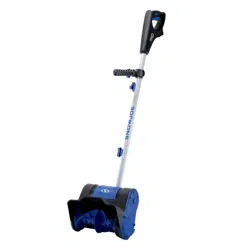
Connecting the Poles
1. Slide the middle pole into the lower pole assembly and the
upper pole assembly. Align the screw holes (Fig. 4).
2. Insert the joint-xing bolts through the aligned holes in the
poles and secure the other end with the washers and the
joint-xing knobs (Fig. 5). Twist until tight.
NOTE: You may have to carefully move the wiring inside
the tube to one side if it blocks the path of the bolt.
Operation
mWARNING! Keep the area to be cleared free of stones,
toys or other foreign objects that the rotor blades might pick
up and throw. Such items could be covered by snow and are
easy to overlook, so be sure to conduct a thorough inspection
of the area before beginning work.
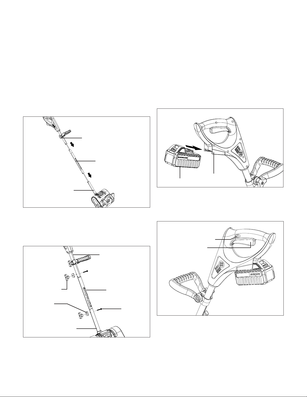
Starting the Machine
1. Slide the battery down in the battery compartment until it
clicks to lock it into position (Fig. 6).
2. To start the cordless snow shovel, push and hold the
safety lock switch on the side of the handle grip with your
thumb and then squeeze the trigger switch with your
ngers. Once the machine powers on, you can release the
safety lock switch and proceed with operation (Fig. 7).
3. To stop the cordless snow shovel, release the trigger
switch.
Handle Adjustment
To adjust the angle of the auxiliary handle, follow the
instructions below:
1. Stop the machine and remove the battery. Wait until the
blade comes to a completely stop.
Fig. 4
Upper pole
assembly
Middle pole
Lower pole
assembly
Fig. 5
Upper pole
assembly
Middle pole
Lower pole
assembly
Joint-xing
knob
Washer
Bolt
Fig. 6
Battery
Battery
compartment
Fig. 7
Trigger switch
Safety lock switch
Loading ...
Loading ...
Loading ...