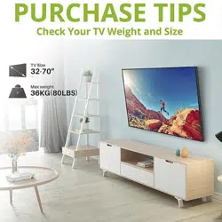

For 37-70" TV
If you have any questions along the way, just give us a call
1-800-460-0956 or mail to [email protected].
We’re ready to help!
XTL006
INSTRUCTION MANUAL
CAUTION: PLEASE READ ENTIRE MANUAL PRIOR TO USE AND SAVE THESE INSTRUCTIONS.
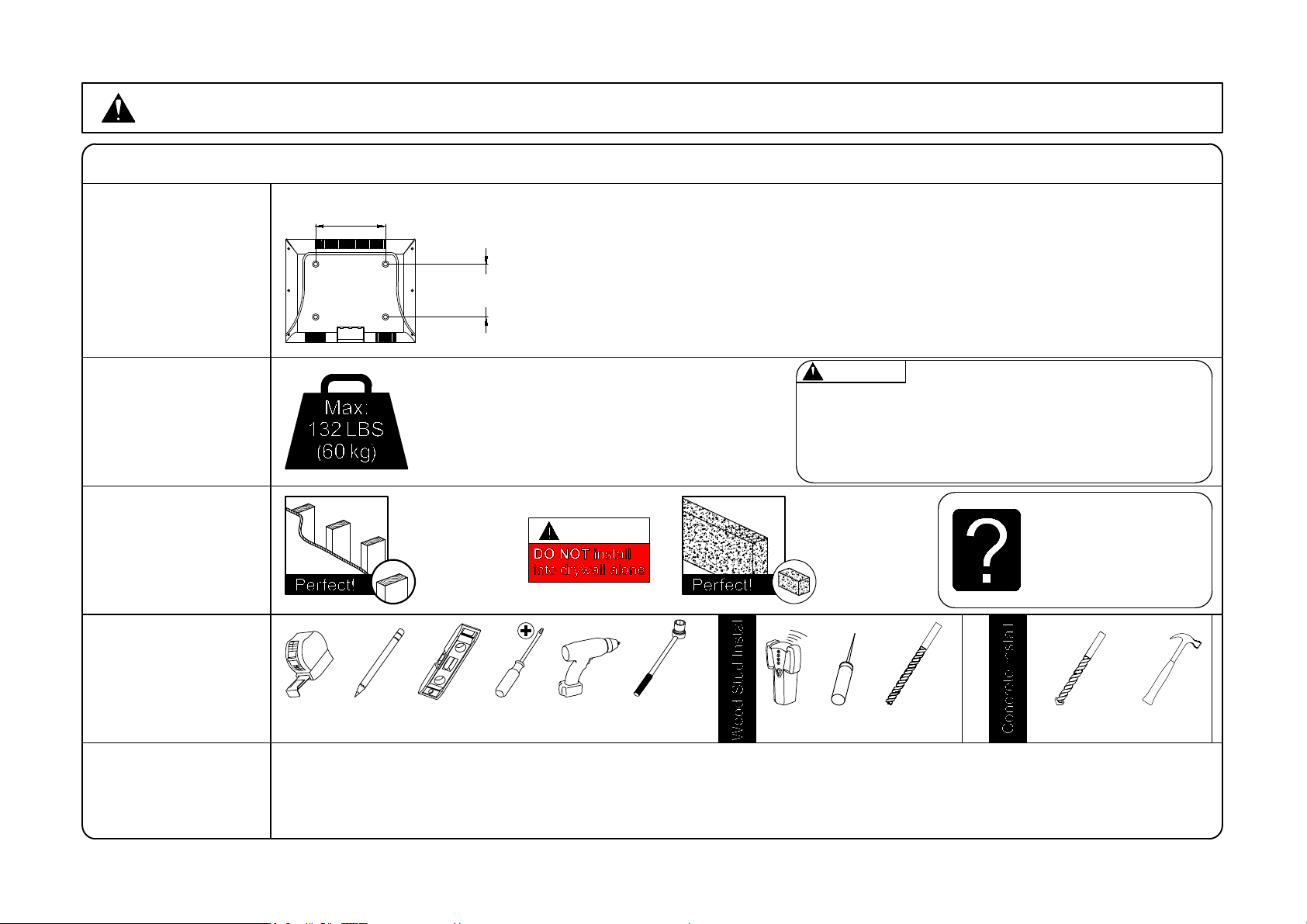
Before getting started, let’s check below lists to make sure it is just right for you!
2
Check your TV
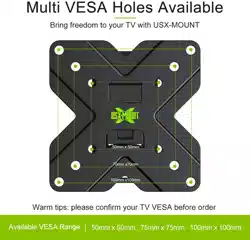
VESA is within
Min and Max size
1
2
3
4
5
Does your TV
(including accessories)
weigh MORE than
132 lbs. (60 kg)?
What is your
wall made of?
Do you have
all the tools
needed?
(Not included)
Caution
MAX:600mm/23.6"
(MIN:200mm/7.9")
MAX:400mm/15.7"
(MIN:100mm/3.9")
No? This mount is NOT compatible.
Yes? Perfect !
No? Perfect – you may continue.
Yes? This mount is NOT compatible.
CAUTION: DO NOT exceed the maximum weight
indicated. This mounting system is intended for use only
with the maximum weights indicated. Use with products
heavier than the maximum weights indicated may result
in collapse of the mount and its accessories, causing
possible injury.
CAUTION:
Drywall with
wood studs?
Solid concrete
Unsure?
Call Customer Service:
1-800-460-0956
Socket
Wrench
1/2"(13mm)
Electric
Drill
Screw
driver
LevelPencil
Tape
Measure
Stud
Finder
7/32"(5.5mm)
Wood Drill Bit
3/8"(10mm)
Masonry Drill Bit
Hammer
● This product is designed for use in wood stud, solid concrete walls - DO NOT install into drywall alone
● The wall must be capable of supporting five times the weight of the TV and mount itself
● Do not use this product for any purpose not explicitly specified by manufacturer
● Manufacturer is not responsible for damage or injury caused by incorrect assembly or use
Awl
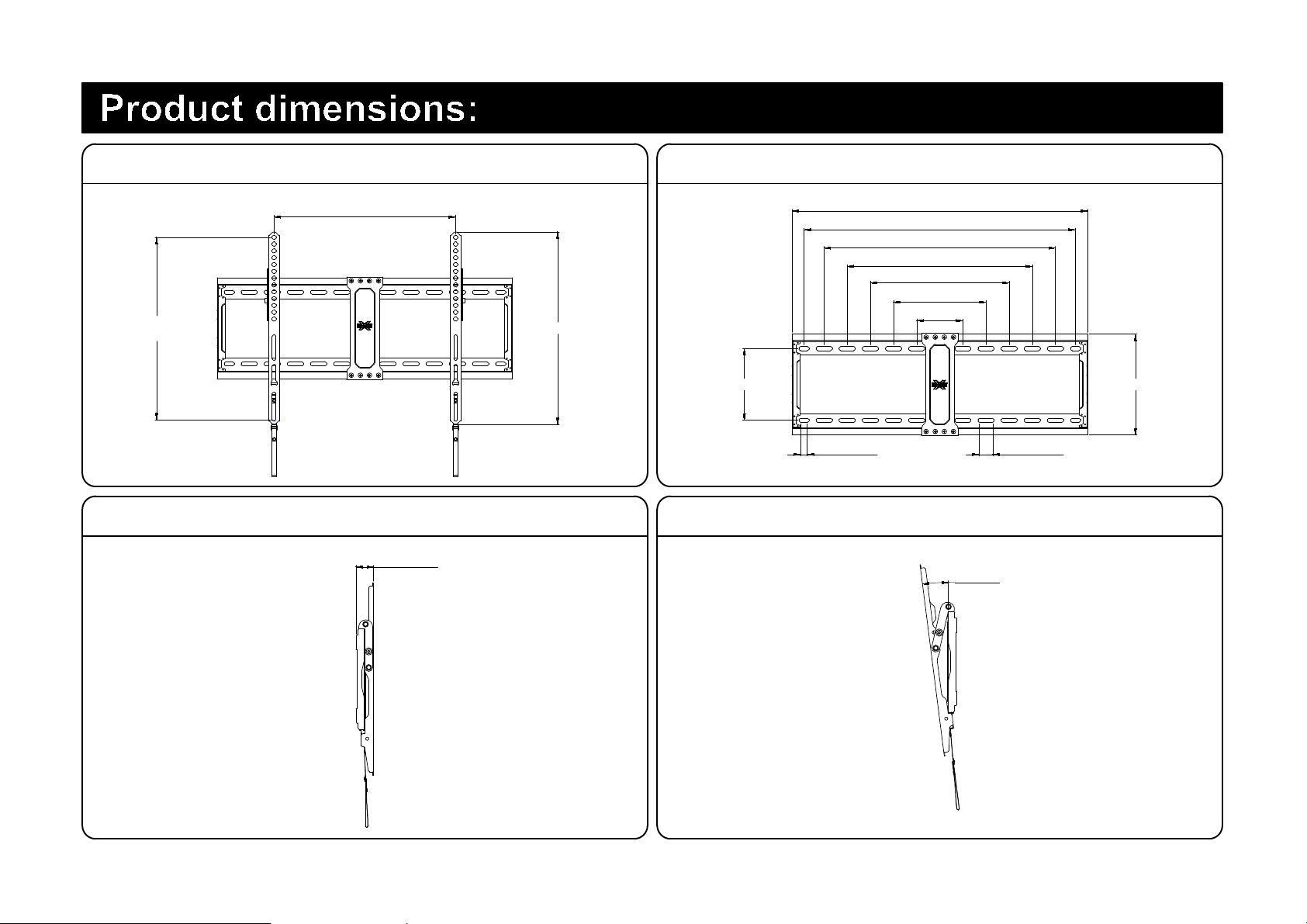
3
TV INTERFACE WALL PLATE
SIDE VIEW SIDE VIEW
MAX:600mm/23.6"
MIN:200mm/7.9"
MAX:400mm/15.7"
MIN:100mm/3.9"
424mm/16.7"
102mm/4"
203.5mm/8"
305.5mm/12"
407.5mm/16"
509.5mm/20"
598mm/23.5"
16mm/0.6" 30mm/1.2"
158mm/6.2" 222mm/8.7"
650.5mm/25.6"
38mm/1.5"
0°~ -8°

4
WARNING: This product contains small items that could be a choking hazard if swallowed. Before starting assembly, verify all parts
are included and undamaged. If any parts are missing or damaged, do not return the damaged item to your dealer; contact
Customer Service.
Never use damaged parts!
NOTE: Not all hardware included will be used.
Parts and Hardware
TV Brackets
x1 x1
M4x12mm
M6x12mm
M8x25mm
M4x30mm
M6x35mm
M8x50mm
M6x17mm
M8x22mm
M4
M6
10mm
2.5mm
Washers
Spacers
TV Screws
x4 x4
x4 x4
x4 x4
x4
x4
x4
x4
x8
x4
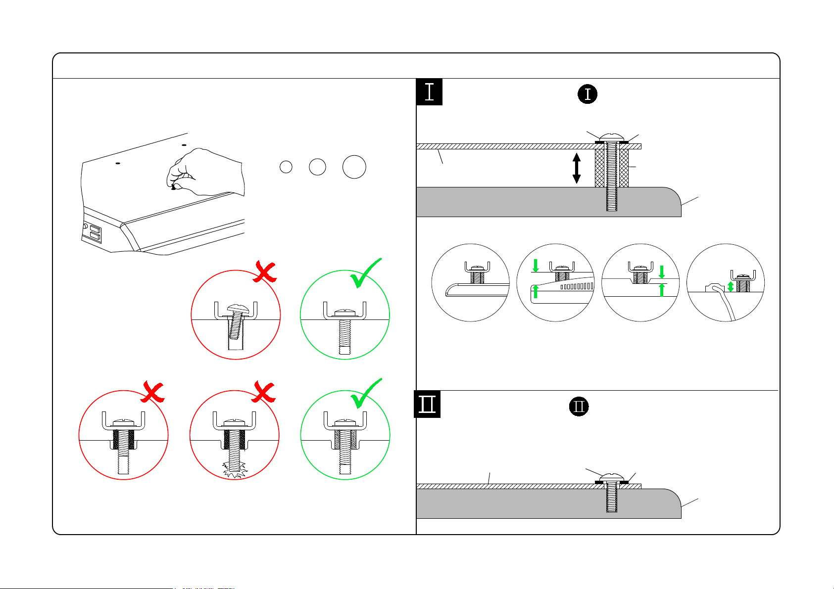
TV back
Bracket
Washer
Bracket
Long Screw
Spacer
Yes, go to PAGE 6 for detailed combination.
No, go to PAGE 6 for detailed combination.
TV back
1-2 Need Spacer?
Short Screw
Washer
5
1-1 Select TV Screws
M8
M6
M4
Highly recommended to add spacers for more
spacing between wall mount and wall.
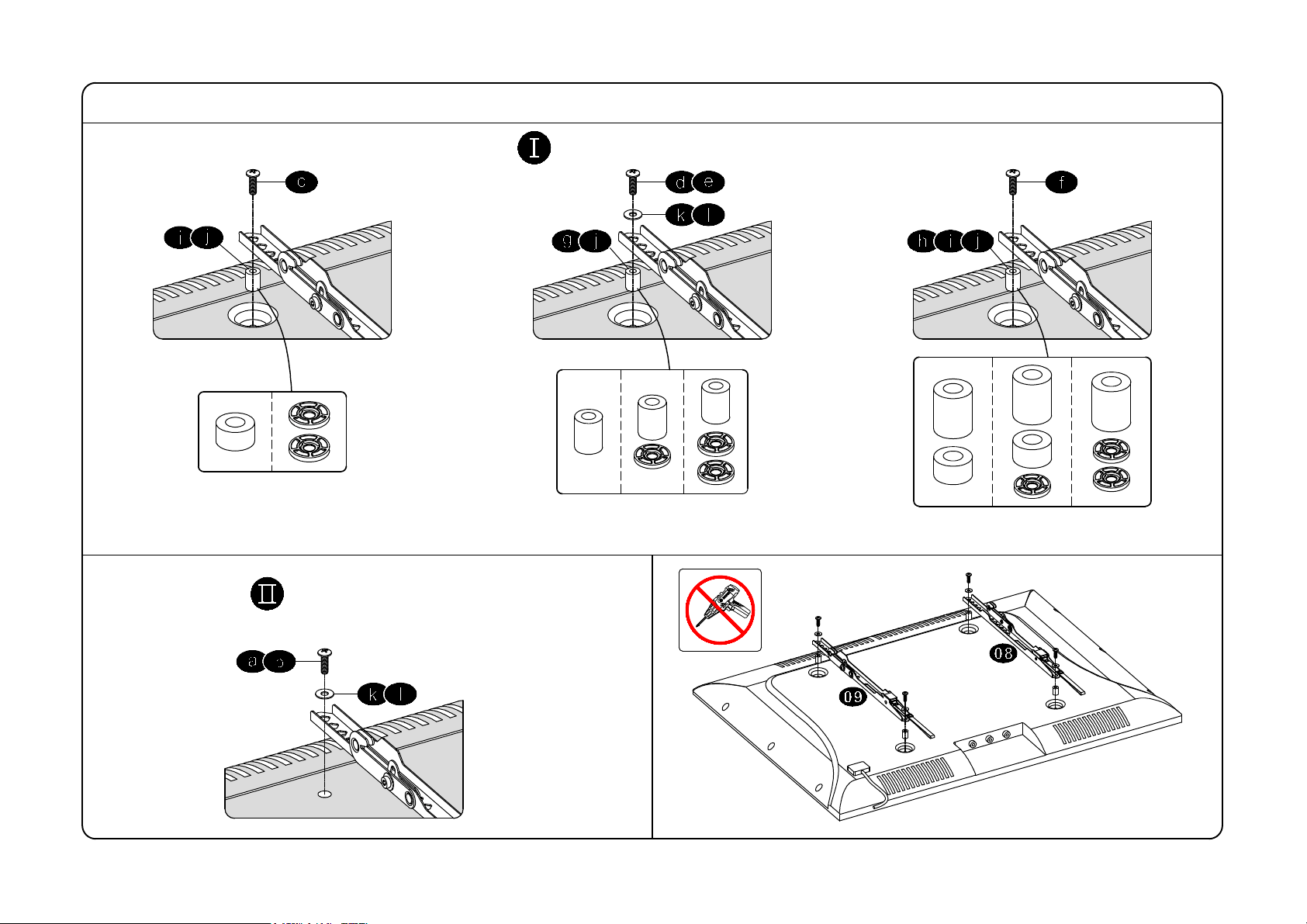
1-3
Attach the TV Brackets
6
Screw and washer
Spacer(s), screw and washer
No!
Tips: If you need to combine M6/M8(c/e/f) screw with 2.5mm spacer(j), you have to remove the inner circle.
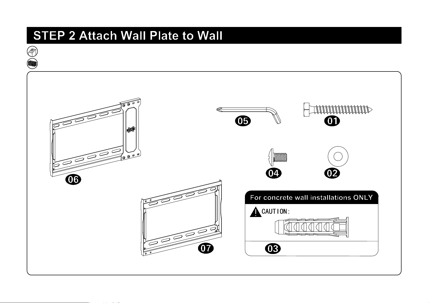
For wood stud installation, follow STEP 2A on PAGE 9
For concrete installation, follow STEP 2B on PAGE 12
Parts and Hardware
7
Concrete Wall Anchor 4pcs
Do not use in drywall or wood
Lag Bolt M8x60mm
M8 Washer
x4
x4
Allen Key
x1
x4
M5x8mm Bolt
Wall plate(Left)
x1
Wall plate(Right)
x1
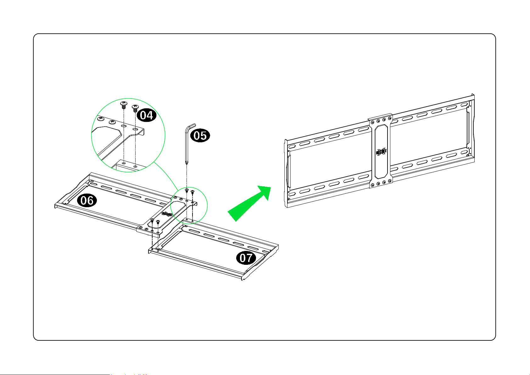
8
Assemble Wall plate
Wall plate unit
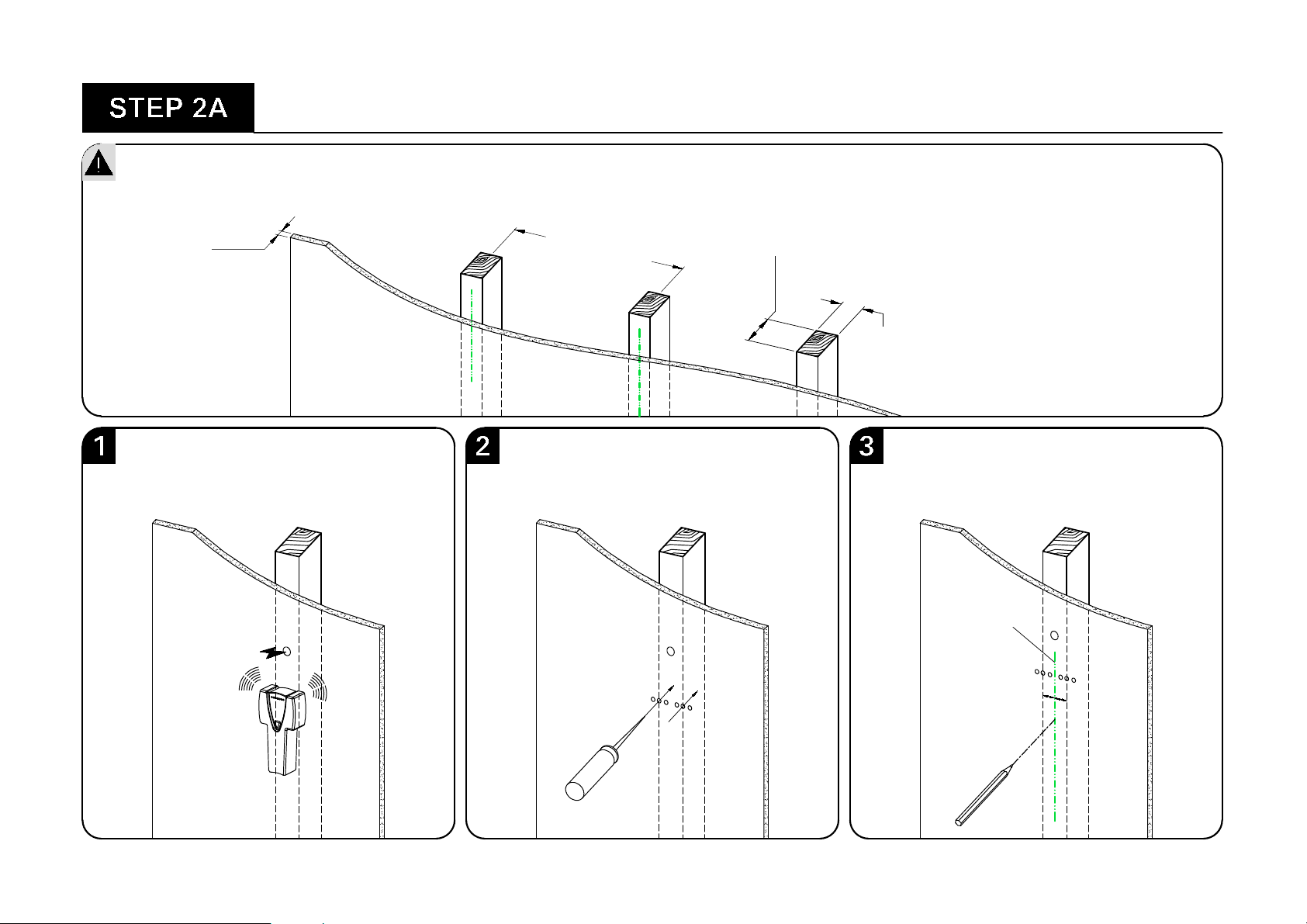
<16mm
(5/8")
609.6mm/24"
406mm/16"
Min. Wood Stud Size:
nominal 2"(51mm)
actual 1 1/2"(38mm)
Min. Wood Stud Size:
nominal 4"(102mm)
actual 3 1/2"(89mm)
Wood Stud Installation
O
Centre line
9
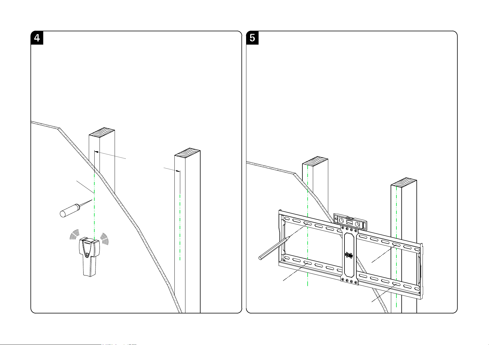
24"(609.6mm)
16"(406mm)
Centre line
Again, find another wood stud
10
Wall plate unit
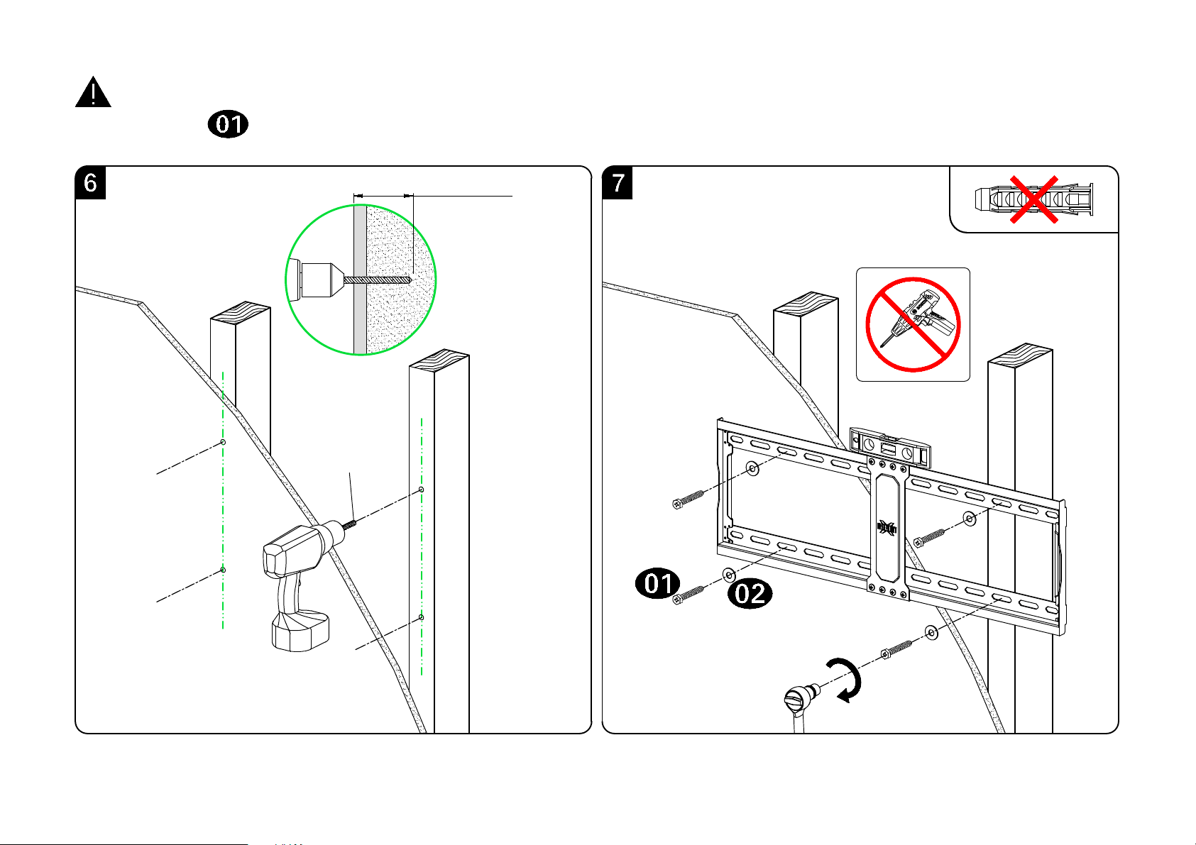
7/32"
(5.5mm)
2.5"(64mm)
CAUTION: To avoid potential personal injury or property damage:
All 4 lag bolts MUST BE firmly tightened to prevent unwanted movement of the wall plate assembly.
Ensure the wall plate assembly is securely fastened to the wall before continuing on to the next step.
Go to Step 3 on PAGE 14.
11
No!
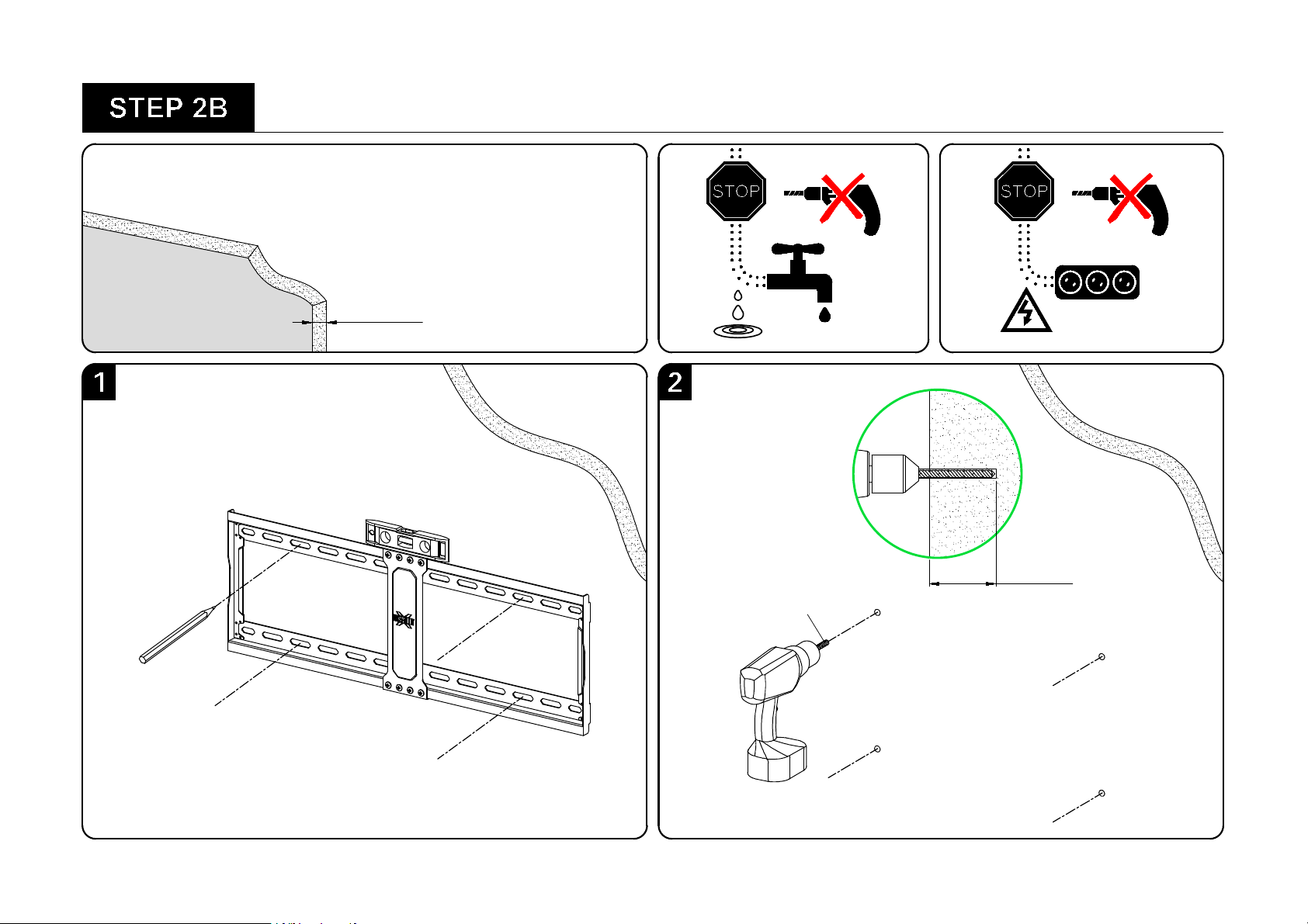
Solid Conrete Wall Installation
DANGER
Min.
8"(203mm)
2.5"
(64mm)
3/8"
(10mm)
3/8"
(10mm)
12
Wall plate unit
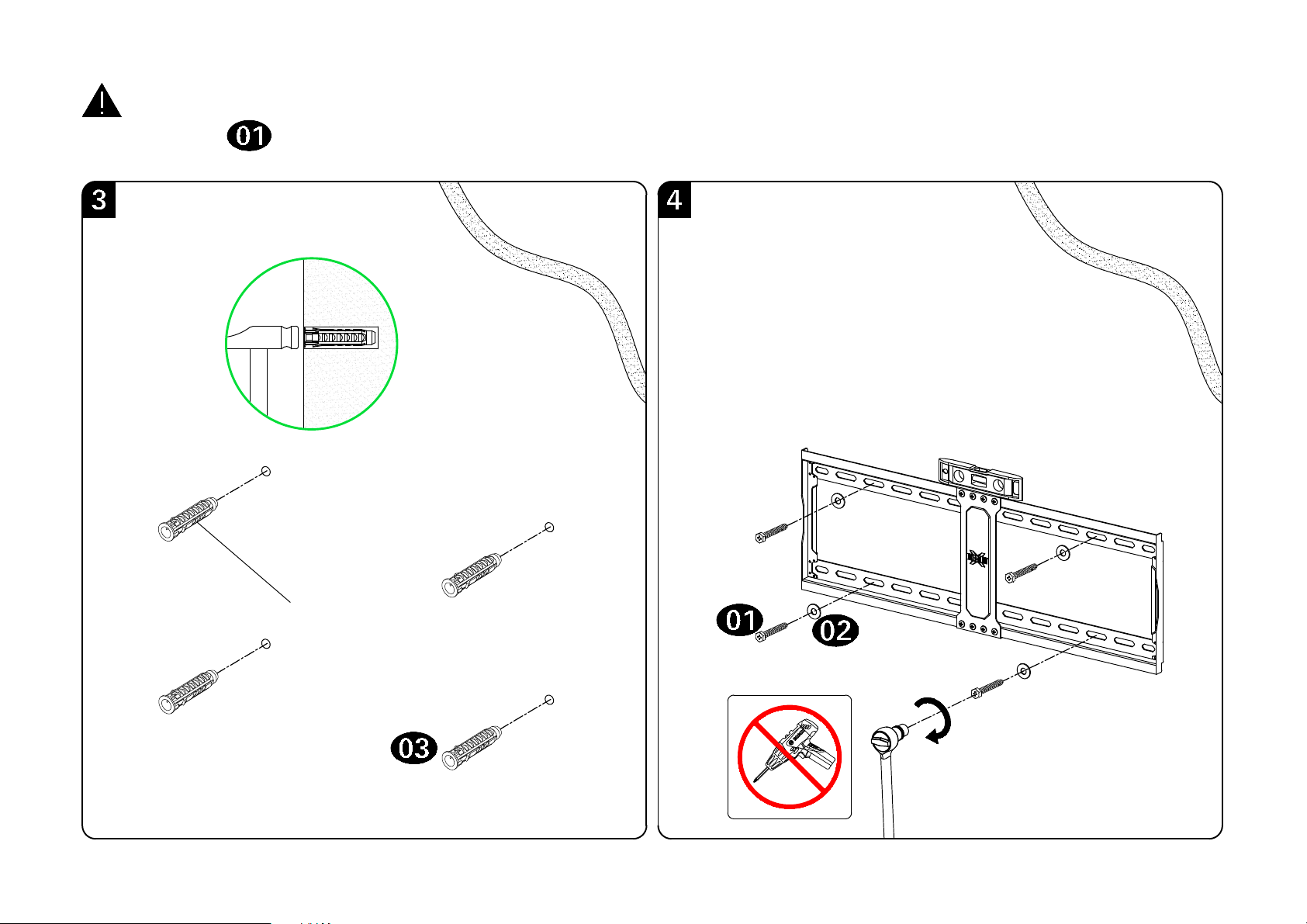
CAUTION: To avoid potential personal injury or property damage:
All 4 lag bolts MUST BE firmly tightened to prevent unwanted movement of the wall plate assembly.
Ensure the wall plate assembly is securely fastened to the wall before continuing on to the next step.
Concrete Wall
Anchor
13
No!
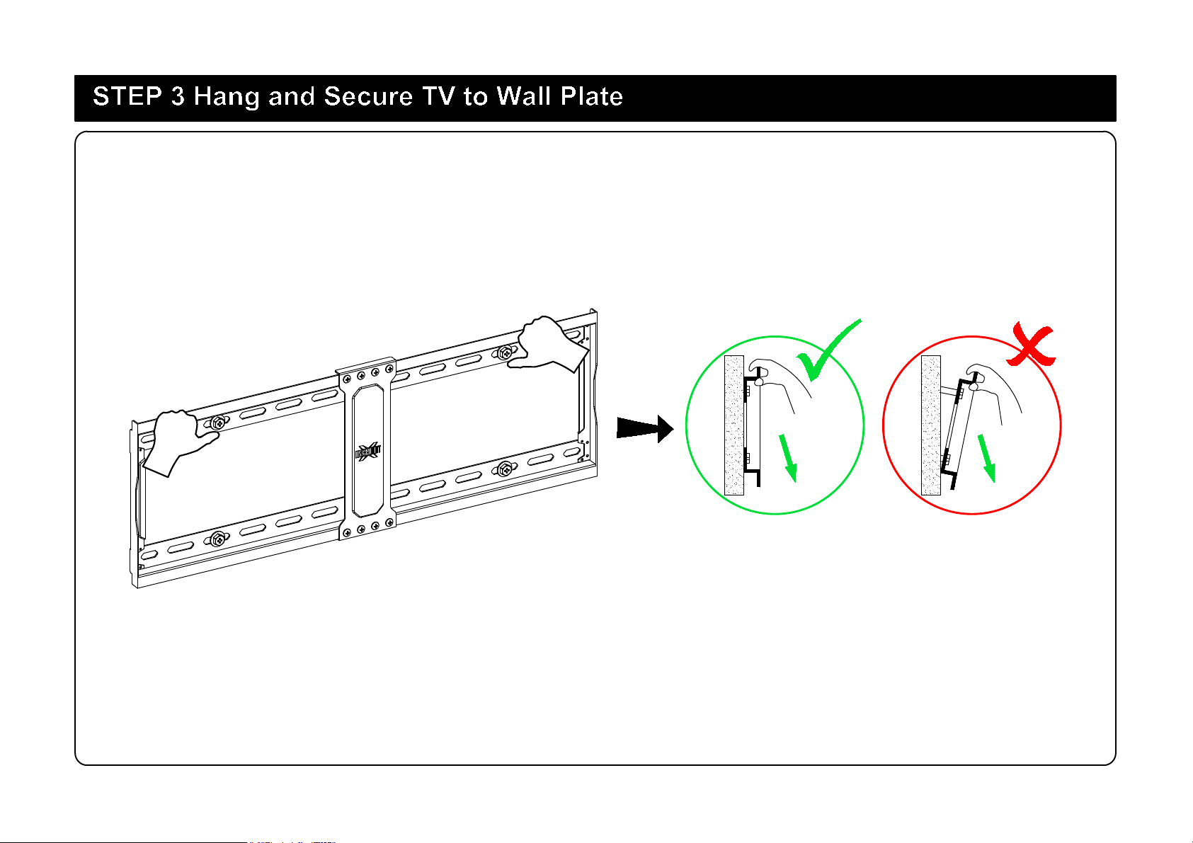
Before hanging TV, please conduct "wall plate installation integrity test" first.
14
132 LBS (60 kg)
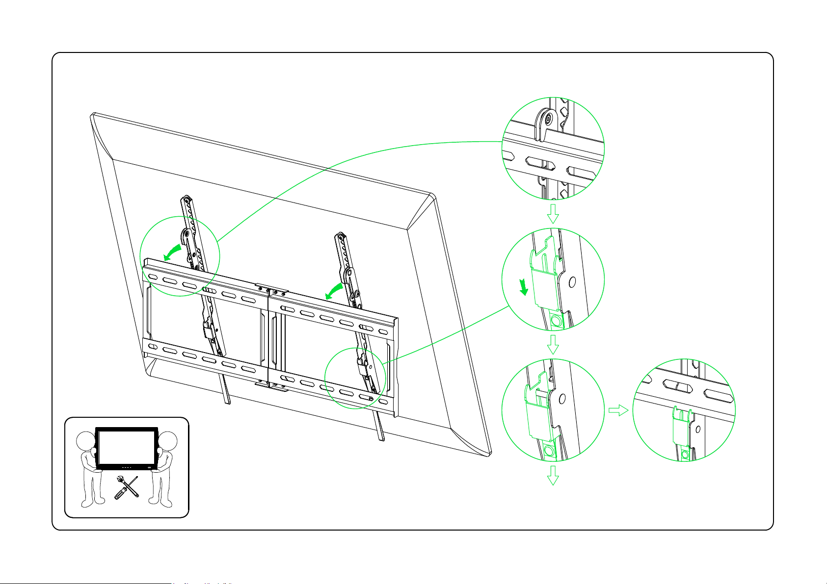
TV
1 2
15
Pull down
16
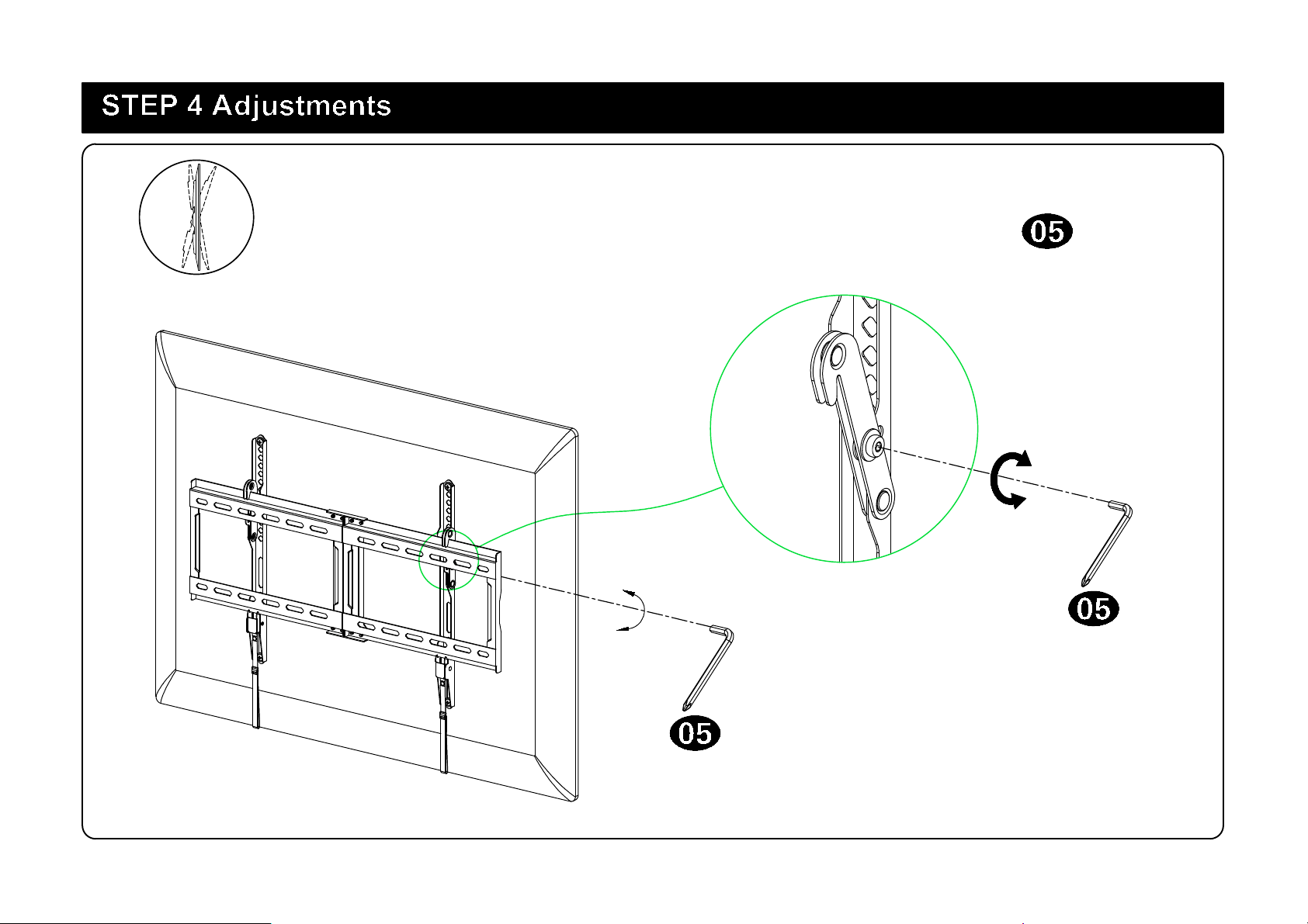
Tilting angle adjustment (0°/-8°):
Pull TV to your desired angle then fasten 2 tilting bolts with Allen key .
0°
-8°
Loosen
Tighten
17
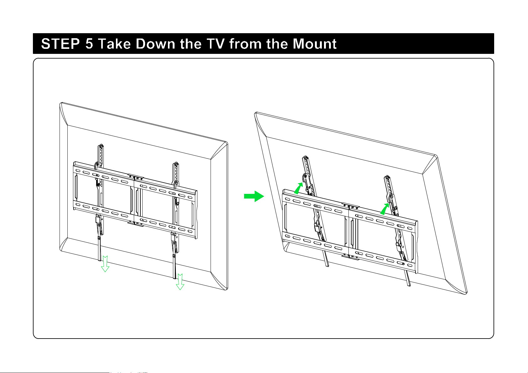
Pull down
the straps