User Manual GE - General Electric TPX24PBZ Legacy
Preparing to install the refrigerator
Water Supply to the Icemaker
You will need to connect the icemaker to a cold water line.
A water supply kit (containing copper tubing, shutoff valve, fittings and instructions) is available at extra cost from your dealer or from Parts and Accessories, 800-626-2002.
Refrigerator Location
Install it on a floor strong enough to support it fully loaded.
Clearances
Allow the following clearances for ease of installation, proper air circulation and plumbing and electrical connections
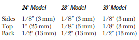
If built-in, allow 7/8'' (22 mm) for hinge covers
If the refrigerator is against a wall on either side, allow 3/4'' (19 mm) for freezer door clearance and 3/4'' (19 mm) for fresh food door clearance.
Leveling Rollers
The rollers have 2 purposes:
- The rollers can be adjusted so the refrigerator is firmly positioned on the floor and does not rock back and forth.
- Rollers allow you to move the refrigerator away from the wall for cleaning.
To adjust the rollers, remove the base grille by pulling it out at the bottom.
Turn the two front roller adjusting screws clockwise to raise the refrigerator, counterclockwise to lower it. Use a 3/8'' socket wrench, adjustable wrench or pliers.
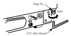
Door Alignment
After leveling, make sure that doors are even at the top
To make the doors even, adjust the fresh food door. Insert a 3/16² Allen wrench into the bottom of the hinge pin. Turn the door adjusting screw to the right to raise the door, to the left to lower it. (A nylon plug, imbedded in the threads of the pin, prevents the pin from turning unless a wrench is used.) After one or two turns of the wrench, open and close the fresh food door and check the alignment at the top of the door
Dimensions and Specifications(for Built-In Style models)

Trim kits and decorator panels
Before You Begin
Some models are equipped with trim kits that allow you to install door panels. You can order pre-cut black or white decorator panels from GE Parts and Accessories, 800-626-2002, or you can add wood panels to match your kitchen cabinets.
Panels less than 1/4'' (6 mm) thick
When installing wood panels less than 1/4'' (6 mm) thick, you need to create a filler panel, such as 1/8² cardboard, that will fit between the face of the door and the wood panel. If you are installing the pre-cut decorator panels, pre-cut filler panels are included in the kit. The combined thickness of the decorator or wood panel and the filler panel should be 1/4'' (6 mm).
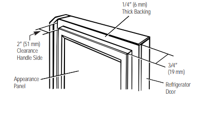
3/4'' (19 mm) or Raised Panel
A raised panel design screwed or glued to a 1/4'' (6 mm) thick backing, or a 3/4'' (19 mm) routed board can be used. The raised portion of the panel must be fabricated to permit clearances of at least 2'' (51 mm) from the handle side for fingertip clearance.
Weight limitations for custom panels:
Fresh Food 35 lb. (16 kg) max.
Freezer Door 25 lb. (11 kg) max.
Dimensions for Custom Wood Panels
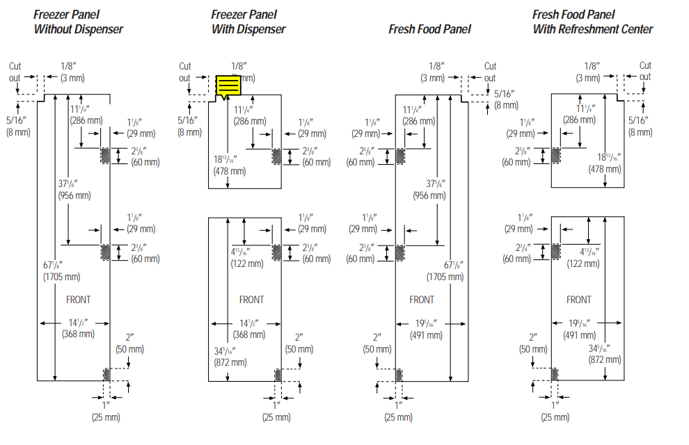
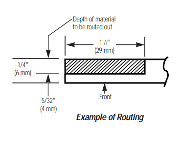
The areas at the top of the panels need to be cut out of the panels. The shaded areas indicate areas that must be routed out about 5/32'' (4 mm) on the back side of panels 1/4'' (6 mm) thick or more. For panels less than 1/4'' (6 mm) thick, these areas can be cut out of the filler panels.
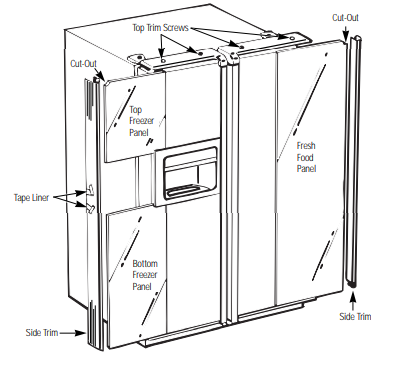
Inserting the door panels
1. Loosen the Top Trim on the Freezer and Fresh Food Doors.
Using a T-20 Torx driver, loosen the two screws attaching the Top Trim about 1/4'' (6 mm)
2. Insert the Freezer Panel and Fresh Food Panel.
Lift the Top Trim up 1/4'' (6 mm) and carefully push the freezer panel in until it slides into the slot behind the door handle. Push the filler panel (required with some door panels) in behind the decorator panel. Repeat for fresh food panel.
If your model has a dispenser and/or a Refreshment Center, this step only applies to the top panels.
3. Insert the Bottom Panel (for models with a dispenser and/or a Refreshment Center)
Carefully push the panel in until it slides into the slot behind the door handle. Push the filler panel (required with some door panels) in behind the decorator panel.
4. Tighten the two screws on the Top Trim to 30 in-lbs torque
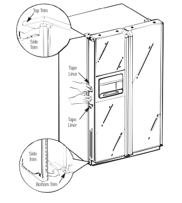
5. Install the Side Trim.
These pieces are tucked inside the fresh food door handle. Do not remove the protective film on the outside of the Side Trim until the Side Trim is installed. Fit the bottom of the Side Trim under the Bottom Trim as illustrated.
Hold the Side Trim against the front face of the decorator panels and fit the Side Trim under the Top Trim. Make sure the Side Trim is fitted correctly and that you are satisfied with the appearance of all the parts before pulling the tape liner.
Continue pulling the tape liner loose, alternating between the top and bottom and pressing the Side Trim against the door.
6. Secure the Side Trim
Place one hand between the two pieces of tape liner and hold the Side Trim firmly against the panels and the side of the door.
Pull the top tape liner up about 3'' (80 mm), pressing the trim with your hand as the adhesive is exposed to the door. Then pull the bottom tape liner down about 3'' (80 mm). Follow the tape with your hand, pressing the trim adhesive against the door.
7.Remove the Protective Film From the Outside of the Side Trim.
Installing and removing previously installed decorator panels
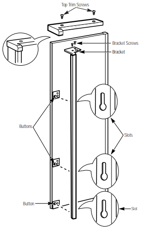
Removing the Handles
In order to remove the decorator panels and replace with new panels you need to remove the handles. A T-20 Torx driver is needed.
- Loosen and remove the 2 screws in the Top Trim.
- Loosen and remove the 2 screws in the bracket that attaches the Handle to the top of the Door.
- Grip the Handle firmly and slide upwards. The keyhole slots on the Handle slide off the buttons on the door
- Open the door and slide out the decorator panel
Inserting the Door Panels
Before installing the decorator panels, make sure they have been routed out in the proper areas as shown in the beginning of this section. Slide in the panels to perform a trial fit before fastening down the Handle and Top Trim.
Installing the Handles
Once the panels are fitted properly, install the Handle and Top Trim.
- Slide the keyhole slots on the Handle down onto the buttons mounted to the face of the door. Slide the Handle downward until the bracket at the top of the Handle fits flush on the top of the door.
- Replace the two screws in the bracket that attach the Handle to the top of the Door and tighten the screws to 45 in-lbs torque
- Replace the Top Trim making sure it fits over the Side Trim and that the locating tabs fit the inside of the Handle profile.
- Replace the Top Trim screws and tighten to 30 in-lbs torque
Installing the water line
Before You Begin
If the water supply to the refrigerator is from a Reverse Osmosis Water Filtration System and the refrigerator is equipped with a built-in filtration system, it is not necessary to use the refrigerator’s water filter. Use the refrigerator’s Filter Bypass Plug. Using the refrigerator’s water filtration cartridge in conjunction with the RO filter can result in hollow ice cubes and slower water flow from the water dispenser
This water line installation is not warranted by the refrigerator or icemaker manufacturer. Follow these instructions carefully to minimize the risk of expensive water damage.
Water hammer (water banging in the pipes) in house plumbing can cause damage to refrigerator parts and lead to water leakage or flooding. Call a qualified plumber to correct water hammer before installing the water supply line to the refrigerator
To prevent burns and product damage, do not hook up the water line to the hot water line.
If you use your refrigerator before connecting the water line, make sure the icemaker feeler arm is kept in the STOP (up) position.
Do not install the icemaker tubing in areas where temperatures fall below freezing
When using any electrical device (such as a power drill) during installation, be sure the device is insulated or wired in a manner to prevent the hazard of electric shock.
All installations must be in accordance with local plumbing code requirements.
What You Will Need
To determine how much copper tubing you need:
Measure the distance from the water valve on the back of the refrigerator to the water supply pipe. Then add 8 feet (244 cm). Be sure there is sufficient extra tubing [about 8 feet (244 cm) coiled into 3 turns of about 10 inches (25 cm) diameter] to allow the refrigerator to move out from the wall after installation.
- A water supply kit (containing copper tubing, shutoff valve and fittings listed below) is available at extra cost from your dealer or from Parts and Accessories, 800-626-2002.
- Cold water supply. The water pressure must be between 40 and 120 p.s.i.
- Power drill
- Copper tubing, 1/4" outer diameter to connect the refrigerator to the water supply. Be sure both ends of the tubing are cut square.
Do not use plastic tubing or plastic fittings because the water supply line is under pressure at all times. Certain types of plastic tubing may become brittle with age and crack, resulting in water leakage.
- Two 1/4'' outer diameter compression nuts and 2 ferrules (sleeves)—to connect the copper tubing to the shutoff valve and the refrigerator water valve.
- If your existing water line has a flared fitting at the end, you will need an adapter (available at plumbing supply stores) to connect the water line to the refrigerator OR you can cut off the flared fitting with a tube cutter and then use a compression fitting.
- Shutoff valve to connect to the cold water line. The shutoff valve should have a water inlet with a minimum inside diameter of 5/32'' at the point of connection to the COLD WATER LINE. Saddle-type shutoff valves are included in many water supply kits. Before purchasing, make sure a saddle-type valve complies with your local plumbing codes.
Shut Off the Main Water Supply
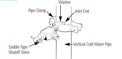
Install the Shutoff Valve
- Install the shutoff valve on the nearest frequently used drinking water line.
- Choose a location for the valve that is easily accessible. It is best to connect into the side of a vertical water pipe. When it is necessary to connect into a horizontal water pipe, make the connection to the top or side, rather than at the bottom, to avoid drawing off any sediment from the water pipe.
- Drill a 1/4'' hole in the water pipe, using a sharp bit. Remove any burrs resulting from drilling the hole in the pipe.
- Fasten the shutoff valve to the cold water pipe with the pipe clamp.
- Tighten the clamp screws until the sealing washer begins to swell.
Do not overtighten or you may crush the copper tubing
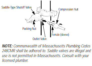
NOTE: Commonwealth of Massachusetts Plumbing Codes 248CMR shall be adhered to. Saddle valves are illegal and use is not permitted in Massachusetts. Consult with your licensed plumber
Route the Copper Tubing and Connect It to the Shutoff Valve
Route the copper tubing between the cold water line and the refrigerator
Route the tubing through a hole drilled in the wall or floor (behind the refrigerator or adjacent base cabinet) as close to the wall as possible.
Be sure there is sufficient extra tubing [about 8 feet (244 cm) coiled into 3 turns of about 10'' (25 cm) diameter] to allow the refrigerator to move out from the wall after installation.
Place the compression nut and ferrule (sleeve) onto the end of the tubing and connect it to the shutoff valve.
Make sure the tubing is fully inserted into the valve. Tighten the compression nut securely.
Turn On the Water and Flush Out the Tubing
- Turn the main water supply on and flush out the tubing until the water is clear.
- Shut the water off at the water valve after about one quart (1 L) of water has been flushed through the tubing.
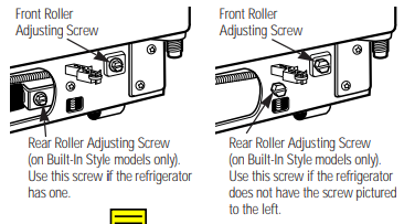
Connect the Tubing to the Refrigerator
Before making the connection to the refrigerator, be sure the refrigerator power cord is not plugged into the wall outlet.
We recommend installing a water filter if your water supply has sand or particles that could clog the screen of the refrigerator’s water valve. Install it in the water line near the refrigerator.
- Remove the plastic flexible cap from the water valve
- Place the compression nut and ferrule (sleeve) onto the end of the tubing as shown.
- Insert the end of the copper tubing into the water valve connection as far as possible. While holding the tubing, tighten the fitting.
- Fasten the copper tubing into the clamp provided to hold it in position. You may need to pry open the clamp
One of the illustrations below will look like the connection on your refrigerator

Turn the Water On at the Shutoff Valve
Tighten any connections that leak.
Plug In the Refrigerator
Arrange the coil of copper tubing so that it does not vibrate against the back of the refrigerator or against the wall.
Push the refrigerator back to the wall
Start the Icemaker
Set the icemaker feeler arm to the ON (down) position. The icemaker will not begin to operate until it reaches its operating temperature of 15°F. (-9°C.) or below. It will then begin operation automatically if the icemaker feeler arm is in the ON (down) position.
NOTE: The icemaker may double-cycle when it first starts, causing some water spillage from the icemaker into the ice bucket. This is normal and should not happen again

