Monogram.
Use and Care
and Installation
Guide
for ZEW145
ZEW154
ZEW155
ZEW164
ZEW165
ZEW1’75
ZGW124
ZGW125
Component Cooktop
Svstem
Monogram:’”
Component Cooktuf)
164D2966P016
Introduction
Your new Monogram cooktop makes an eloquent statement of style,
convenience and kitchen planning flexibility. Whether you chose it for
its purity of design, assiduous attention to detail-or for both of these
reasons—you’ll find that your Monogram cooktop’s superior blend of
form and function will delight you for years to come.
The ZEW and ZGW Monogram cooktops were designed to provide the
flexibility to blend in with your kitchen cabinetry. Their sleek design can
be beautifully integrated into the kitchen.
The information on the following pages will help you operate and maintain
your component cooktop system properly.
If you have any other questions—please call the GE Answer Center”
800.626.2000.
Contents
Appliance Registration .................3
Grill Component ...................l9–22
Canning
.......................................
16 Halogen/Radiant Component.. 13-15
Care and Cleaning ................26-30
Installation Instructions ........33-60
Components Information ..........7-9
Model and Serial Numbers ...........3
Consumer Services .....................62
Problem Solver .....................3l. 32
Controls
................................
11, 12 Safety Instructions ....................4-7
Cooktop Comparison ..................lO
Wamanty .....................................
63
Gas Burner Component ........17–19
Questions?
Griddle Accesso~ ................23–25
Call GE Answer Center@
800.626.2000
WARNING: If the information in this
manual is not followed exactly, afire or
explosion may result causing property
damage, personal injury or death.
— Do not store or use gasoline or other
flammable vapors and liquids in the
vicinity of this or any other appliance.
— WHAT TO DO IF YOU SMELL GAS
● Do not try to light any appliance.
● Do not touch any electrical switch; do
not use any phone in your building.
● Immediately call yourzyxwvutsrqponmlkjihgfedcbaZYXWVUTSRQPONMLKJIHGFEDCBAgas supplier from
a neighbor’s phone. Follow the gas
supplier’s instructions.
. If you cannot reach your gas supplier>
call the fire departmen~
— Installation and service must be
performedby a qualitledinstaller, service
agency or the gas supplier.
2
Before using your cooktop system, read this guide carefully.
It is intended to help you operate and maintain your new cooktop
components properly.
Keep it handy for answers to your questions.
If you don’t understand something or need more help, write (include your
phone number):
Consumer Affairs
GE Appliances
Appliance Park
Louisville, KY 40225
Write down the model and serial numbers.
You’ll find them on a label on the bottom of each component.
These numbers are also on the Consumer Product Ownership Registration
Card that came with your cooktop system components. Before sending in
this card, please write these numbers here:
Component Model Number
Component
Model Number
Serial Number Serial Number
Use these numbers in any
Component
Model Number
comespondence or service calls
concerning your oven.
Serial Number
If you received any damaged cooktop components...
Immediately contact the dealer (or builder) that sold you the cooktop system.
Save time and money. Before you request service...
Check the Problem Solver in the back of this guide. It lists causes of minor
operating problems that you can correct yourself.
If you need service...
To obtain service, see the
Consumer Services page in the
back of this guide.
We’re proud of our service and
want you to be pleased. If for some
reason you are not happy with the
service you receive, here are three
steps to follow for further help.
FIRST, contact the people who
serviced your appliance. Explain
why you are not pleased. In most
cases, this will solve the problem.
NEXT, if you are still not pleased,
write all the details-including
your phone number—to:
Manager, Consumer Relations
GE Appliances
Appliance Park
Louisville, KY 40225
FINALLY, if your problem is still
not resolved, write:
Major Appliance Consumer
Action Panel
20 North Wacker Drive
Chicago, IL 60606
3
IMPORT~ SAFETY INSTRUCTIONSzyxwvutsrqponmlkjihgfedcbaZYXWVUTSRQPONMLKJIHGFEDCBA
Read all instructions before using this appliance.
IMPORTM SAFETY NOTICE
. TheCalifornia Safe Drinking Water and Toxic
EnforcementAct requires the Governor of
California to publish a list of substances known to
the state to cause cancer, birth defects or other
reproductive h- and requires businessesto warn
customers of potential exposure to such substances.
● Gas appliances can cause minor exposure to
four of these substances, namely benzene,
carbon monoxide, fommldehyde and SOOLcaused
primarily by the incomplete combustion of natural
gas or LP fuels. Properly adjusted burners,
indicated by a bluish rather than a yellow flame,
will minimize incomplete combustion. Exposure
to these substances can be minimized further by
venting with an open window or using a
ventilation fan or hood.
When You Get Your Component
Cooktop System
● Have your cooktop installed and properly
grounded by a qualified installer in accordance
with the Installation Instructions. Any adjustment
and service should be performed only by qualified
gas and electric appliance installers or service
technicians.
● Have the installer show you the location of the
circuit breaker or fuse Mark it for easy reference.
● Havetheinstaller show you the locationof
thegascut-offvalveandhowto shutit off
if necessary.
For Your Safety
When using the component cooktop system, basic
safety precautions should be followed, including
the following:
● Use this cooktop system only for its intended
use as described in this guide.
c If the cooktop is located near a window, do not
use long curtains, which could blow over the gas
burners or surface units, creating a fire hazard.
● Do not attempt to repair or replace any part
of the cooktop system unless it is specifically
recommended in this guide. Any adjustment
and service should be performed only by qualified
electric and gas range installers or service
technicians.
● Before performing any service, DISCONNECT
THE COOKTOP SYSTEM POWER SUPPLY
AT THE HOUSEHOLD DISTRIBUTION
PANEL BY REMOVING THE FUSE OR
SWITCHING OFF THE CIRCUIT BREAKER.
● Do not leave children alone-children should
●
●
●
●
●
●
not be left alone or unattended in an area where an
appliance is in use. They should never be allowed
to sit or stand on any part of the cooktop system.
Avoid installing cabinets above the cooktop
system. To reduce the hazard caused by
reaching into cabinets over hot surface units,
the open flames of operating burners and hot
cookware, install a metal ventilation hood over
the cooktop components that projects forward
at least 5 inches beyond the front of the cabinets.
If cabinets are placed above the cooktop
components, allow a
minimum clearance
of 30 inches between the cooking surface
and the bottom of unprotected cabinets.
CAUTION: ITEMS OF INTEREST TO
CHILDREN SHOULD NOT BE STORED
IN CABINETS INSTALLED ABOVE THE
COOKTOP SYSTEM-CHILDREN
CLIMBING ON THE COOKTOP
SYSTEM TO REACH ITEMS COULD
BE SERIOUSLY INJURED.
Never wear loose-fitting or hanging garments
whaleusing the cooktop system. Be carefid
when reaching for items stored in cabinets over
the cooktop system. Flammable material could
be ignited if brought
in contact with hot surface
units or gas burners and may cause severe bums.
Use only dry pot holders- moist or damp pot
holders on hot surfaces may result in burns from
steam. Do not let pot holders touch the hot surface
units or gas burners and grates. Do not use a towel
or other bulky cloth in place of a pot holder.
For your safety, never use any electric or gas
components of the cooktop system for warming
or heating the room.
4
● Do not s~re fl~mable matefials in an oven or
near the cooktop system components.
● Do not stem or me comb~tible materi~s,
gasoline or other flammable vapors and liquids
in the vicinity of this or any other gas or
electric appliance.
. Do not letzyxwvutsrqponmlkjihgfedcbaZYXWVUTSRQPONMLKJIHGFEDCBACOOking grease or other flammable
materials accumulate in or near the cooktop
system components.
. Never Ieave the kitchen while using the grill
or griddk
QDo not replace the grease collector jar with a
mayonnaise jar which could break when hot
grease drips into it. Replace with any wide mouth
canning jar.
e
I
c Do not use water on grease fires.
s
—
Never pick up a flaming pan. Turn
the controls off. Smother a flaming
pan on a surface unit by covering the pan
completely with a well-fitting hd, cookie sheet or
flat tray. Use a multi-purpose dry chemical or
foam-type fne extinguisher.
Flaming grease outside a pan can be put out by
covering it with baking soda or, if available, by
using a multi-purpose dry chemical or foam-type
fire extinguisher.
● Keep the grill drip pan and grease well clean
to reduce smoking and avoid grease fires.
● To control flame-ups, turn down the heat
setting to low, rather than off(0). This keeps
the downdraft vent blower on. Or, turn the
Variable Speed Vent blower to HI, then turn the
glill off (o).
Use along-handled utensil to carefully remove the
food from the grill.
These steps should control the flame until it
eventually goes out. If it does not, cover the entire
grill module with a cookie sheet or the lid from a
large roasting pan. Use a potholder to remove this
later because it will be hot.
QDo not touch the surface units. These surfaces
may be hot enough to bum even though they are
dark in color. During and after use, do not touch,
or let clothing or other flammable materials
contact the surface units, cooktop surfaces or
areas nearby the surface units. Allow sufficient
time for cooling of the cooking surfaces.
Potentially hot surfaces include the grill grates,
griddle and all components with electric cooking
elements or gas burners and grates.
. When cooking pork, follow the directions
exactly and always cook the meat to an internal
temperature of at least 170”F.This assures that,
in the remote possibility that trichina maybe
present in the meat, it will be killed and the meat
will be safe to eat.
Halogen/Radiant Surface Units
and Gas Burners
● Use proper pan siz*This cooktop system has
components equipped with electric surface units
or gas burners. Select cookware having flat
bottoms large enough to cover the selected surface
unit or burner. The use of undersized cookware
will expose portions of the surface units or
gas burners to direct contact and may result in
ignition of clothing. Proper relationship of
cookware to the surface unit or the burner will
also improve efficiency.
● Only certain types of giass?glass/cerami~
earthenware or other glazed containers are
suitable for cooktop service; others may break
because of the sudden change in temperature.
s Never leave the surface units or gas burners
unattended at high heat settings. Boilovers
cause smoking and greasy spillovers that may
catch fire.
● To minimize the possibility of bums, ignition
of flammable materials and spillage, the handles
of cookware should be turned without extending
over nearby surface units or burners.
. Always ~rn the electric surface unit Or g=
burner controls off (0) before removing the
cookware.
gWatch foods being ffied at high or medium-
high heat settings.
c When flaming foods are under the exhaust
hood, turn the hood fan off. The hood fan,
if operating, may spread the flame.
c Foods for frying should be as dry as possible.
Frost on frozen foods or moisture on fresh foods
can cause hot fat to bubble up and over the sides
of the pan.
(continued next page)
5
IMPORT~ SAFETY INSTRUCTIONS
(continued)
● Use little fat for effective shallow or deep-fat
frying. Filling the pan too fill of fat can cause
spillovers when food is added.
● If a combination of oils or fats will be used
in frying, stir together before heating, or as fats
melt slowly.
. Always heat fat slowly, and watch as it heats.
. Use a deep-fat thermometer whenever
possible to prevent overheating fat beyond
the smoking point.
● Be sure the downdraft vent grille is not covered.
Be sure the filter is in place. Its absence during
cooking could damage blower parts.
● Do not cover or block the area around the
cooktop system knobs. This area must be
kept clear for proper ventilation and burner
performance.
. Keep all plastics away from cooktop surface
units and burners.
● Do not operate the halogenkadiant surface
units if the glass is broken. Spillovers or
cleaning solution may penetrate a broken cooktop
and create a risk of electrical shock. Contact a
qualified technician immediately should your
glass cooktop become broken.
. Avoid scratching the glass cooktop surface.
The cooktop can be scratched with items such
as sharp instruments, rings or other jewelry and
rivets on clothing.
● Never use the glass cooktop surface as a
cutting board.
● Do not place or store items on top of the glass
cooktop surface when it is not in USA
● Do not stand on the glass cooktop.
. Be carefid when placing spoons or other
stirring utensils on the glass cooktop surface
when it is in use. They may become hot and
could cause bums.
● Use care when touching the cooktop. The glass
surface of the cooktop will retain heat after the
controls have been turned off.
. After cleaning, use a dry cloth or paper towel to
remove all Cook Top Cleaning Creme residue.
. Read and follow all instruction and warnings
on Cook Top Cleaning Creme labels.
● Clean the cooktop with caution. If a wet sponge
or cloth is used to wipe spills on a hot surface
unit, be careful to avoid steam bums. Some
cleaners can produce noxious fumes if applied to
a hot surface.
When the cooktop is cool, use only Cook Top
Cleaning Creme brand cleaner to clean the
Cooktop.
QDo not use a wok on the gas burners if the wok
has a round metal ring which is placed over the
burner grate to support the wok. This ring acts
as a heat trap that may damage the burner grate
and burner head. Also, it may cause the burner to
work improperly. This may cause a carbon
monoxide level above that allowed by current
standards, resulting in a health hazard.
. If you smell gas, turn off the gas to the cooktop
at the gas cutoff valve and call a qualified
service technician. Never use an open flame to
locate a leak.
. Do not operate the gas burners without all
burner parts and grate in place.
● Let the gas burner grate and other surfaces
cool before touching them.
● Do not leave grate removed from any
component where children can reach them.
● Never leave gas burners unattended at high
flame settings. Boilovers cause smoking and
greasy spillovers that may catch on fire.
● For your safety, never use your gas burners for
warming or heating the room. Prolonged use of
the cooktop in this way can be hazardous.
● To avoid possible damage to the cooking
surface, do not apply Cook Top Cleaning Creme
to the glass surface when it is hot.
6
Cleaning
If You Need Service
● Do not clean the cooktop system with
flammable or volatile cleaning fluids. See the
Careand Cleaning section.
● Do not clean any part of the cooktop system
when the appliance is in use
● If you are using an overhead exhaust hood,
keep its grease faltersclean to maintain good
venting and to avoid grease fires.
● Clean only parts listed in this Use and
Care Guida
● Clean the cooktop with caution. If a wet sponge
or cloth is used to wipe spills on a hot cooktop, be
careful to avoid steam burns.
s See The Problem Solver section in this guide.
● Do not attempt to rep”?ihor-replace any part
of your component cooktop system unless it
is specifkally recommended in this guide.
All other servicing should be refened to a
qualified technician.
SAm THESE
INSTRUCTIONS
GENERAL INFORMATION ABOUT COMPONENTS
Components available are briefly discussed on this
Read each component section for specific
page. You may only have some installed in your
instructions.
kitchen. All components are permanently installed
with the exception of the grill and griddle.
Care of Components
Some of the components must be cured or
Never immerse any electric surface unit or plug
preconditioned before using them for the first time.
in water.
Components and accessories should be cleaned after
each use. The longer a soil remains, the harder it is to
clean. See each component section in the Care and
Cleaning section for specific instructions.
Electric Surface Unit Components
Gas Components
You must consider heat up and cool down times for
Monogram component gas cooktops (used with either
the surface units when determining cooking times.
updraft or downdraft venting) are designed to operate
Heat up and cool down times depend on initial
on natural gas at 4“ water column pressure.
temperature settings, the type of cookware used and
the amount of food being cooked.
Start cooking at a higher setting to heat the surface
unit faster, then turn to a lower setting to finish
cooking. Remember, cooking continues after the
surface unit is turned off, so train yourself to turn
the heat down or off before cooking is done.
Downdraft Vent
The downdraft vent component features an integral variable-speed blower
control switch and a powerful centrifugal blower.
7
COMPONENTS/ACCESSORIES
To purchase additional components or accessories, contact your nearest
GE Appliances dealer or service center. Part numbers are listed below.
Halogen/Radiant Cooktop
Part Number:
ZEW145
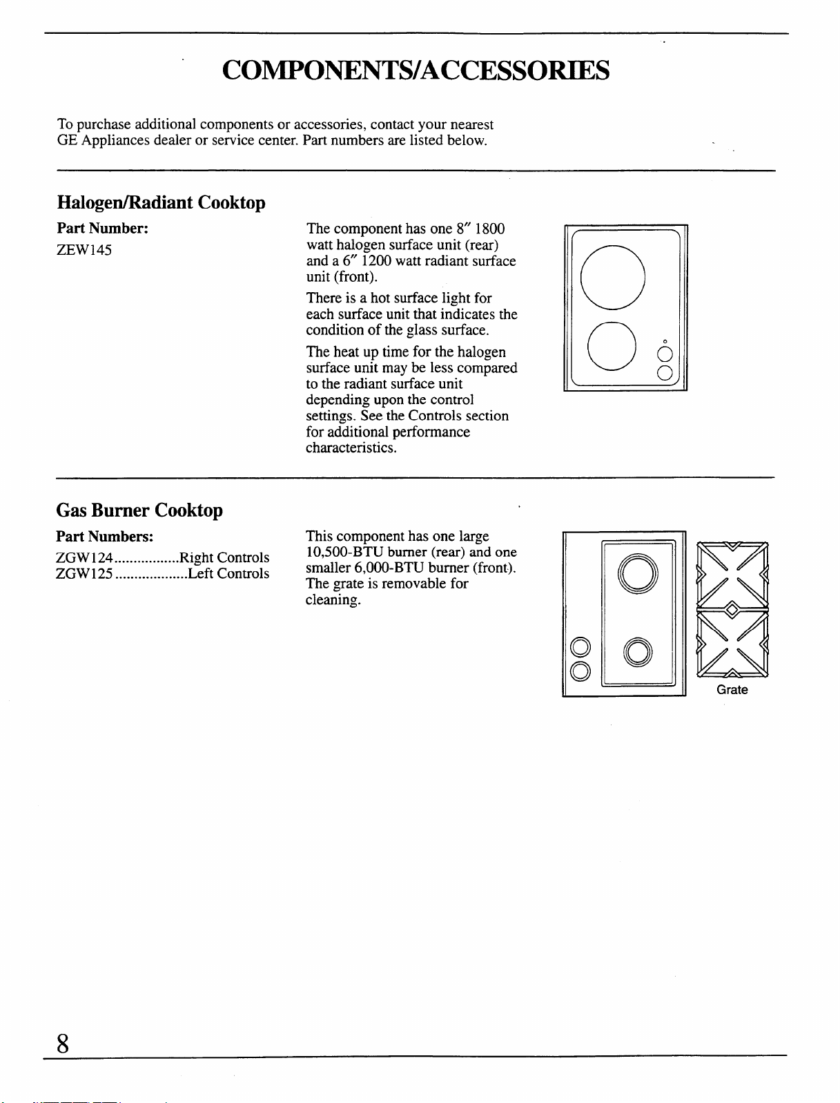
The component has one 8“ 1800
watt halogen surface unit (rear)
and a 6“ 1200 watt radiant surface
unit (front).
There is a hot surface light for
each surface unit that indicates the
condition of the glass surface.
The heat up time for the halogen
surface unit may be less compared
to the radiant surface unit
depending upon the control
settings. See the Controls section
for additional performance
characteristics.
o
0
0
0
0
Gas Burner Cooktop
Part Numbers: This component has one large
ZGW124
--......--.......RightControls
1O,5OO-BTUburner(rear)and one
ZGW125 ...................Left Controls
smaller 6,000-BTU burner(front).
The grateis removable for
clem-ing.
Grate
8
.
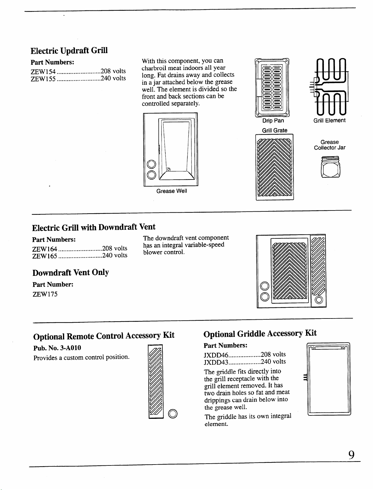
Electric Updraft Grill
Part Numbers:
ZEW154
..........................
208 volts
ZEW155
..........................
240 volts
With this component, you can
charbroil meat indoors all year
long. Fat drains away and collects
in ajar attached below the grease
well. The element is divided so the
front and back sections can be
controlled separately.
.
Grease Well
Electric Grill with Downdraft Vent
Part Numbers:
The downdraftvent component
ZEW164
208 volts
has an integral variable-speed
..........................
ZEW165
240 volts
blower control.
..........................
Downdraft VentzyxwvutsrqponmlkjihgfedcbaZYXWVUTSRQPONMLKJIHGFEDCBAOnly
Part Number:
ZEW175
.’~
Drip Pan
Grill Grate
I
Grill Element
Grease
Collector Jar
151
Optional Remote Control Accessory Kit
Optional Griddle Accessory
Kit
Pub. No. 3-AO1O
Provides a
control
position.
Part Numbers:
JXDD46 ...................2O8 volts
JXDD43 ...................24Ovolts
me griddle fitsdirectly into
the grill receptacle with the
g-ill element removed. It has
two drain holes so fat and meat
drippings
can drain below into
the grease well.
The ~tiddle has its own integral
element.
101
Ior
9
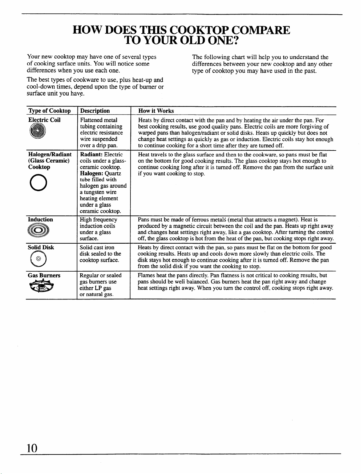
HOW DOES THISCOOKTOP COMPARE
TO YOUR OLD ONE?
Your new cooktop may have one of several types
The following chart
of cooking surface units. You will notice some
differences between
differences when you use each one.
type of cooktop you
The best types of cookware to use, plus heat-up and
cool-down times, depend upon the type of burner or
surface unit you have.
~pe of Cooktop
Electric Coil
e
Halogen/Radiant
(Glass Ceramic)
Cooktop
o
Induction
Solid Disk
o
@
Gas Burners
*
/
Description
Flattenedmetal
tubingcontaining
electricresistance
wiresuspended
over a drip pan.
Radiant: Electric
coils under a glass-
ceramiccooktop.
Halogen: Quartz
tube filled with
halogengas around
a tungstenwire
heatingelement
undera glass
ceramiccooktop.
Highfrequency
inductioncoils
undera glass
surface.
Solid cast iron
disk sealed to the
cooktop surface.
R@~ or sealed
gas burners use
either LP gas
or naturalgas.
will help you to understand the
your new cooktop and any other
may have used in the past.
How it Works
Heats by direct contact with the pan and by heating the air under the pan. For
best cooking results, use good quality pans. Electric coils are more forgiving of
warped pans than halogenhadiant or solid disks. Heats up quickly but does not
change heat settings as quickly as gas or induction. Electric coils stay hot enough
to continue cooking for a short time after they are turned off.
Heat travels to the glass surface and then to the cookware, so pans must be flat
on the bottom for good cooking results. The glass cooktop stays hot enough to
continue cooking long after it is turned off. Remove the pan from the surface unit
if you want cooking to stop.
Pans must be made of ferrous metals (metal that attracts a magnet). Heat is
produced by a magnetic circuit between the coil and the pan. Heats up right away
and changes heat settings right away, like a gas cooktop. After turning the control
off, the glass cooktop is hot from the heat of the pan, but cooking stops right away.
Heats by direct contact with the pti, so pans must be
flat on the bottom for good
cooking results. Heats up and cools down more slowly than electric coils. The
disk stays hot enough to continue cooking after it is turned off. Remove the pan
from the solid disk if you want the cooking to stop.
Flames heat the pans directly. Pan flatness is not critical to cooking results, but
pans should be weli baianced. Gas burners heat the pan right away and change
heat settings right away. When you turn the control off, cooking stops right away.
10
HALOGEN/RADIANT SURFACE UNIT CONTROLS
Halogen Surface Unit
The controls selected for the halogenhadiant
component will give you a full range of heat settings
for cooking.
The control knobs must be pushed down to turn
from the off (0) position. When the control knobs
are in any position other than off(0), they may be
turned without pushing down.
You may notice that the knob that operates the
halogen surface unit is slightly harder to turn than
the knob for the radiant surface unit. This is due
to the difference in design between the two controls.
NOTE:
. The lowest three settings will produce no visible
evidence of the surface unit being on although up
to 11% of the total wattage is being generated. On
the lowest settings, the percentage of power may
not cause the hot surface lights to light. An indicator
light near the control knobs will glow when either
surface unit is on.
● The burner “on” light will glow for all positions
except the off position.
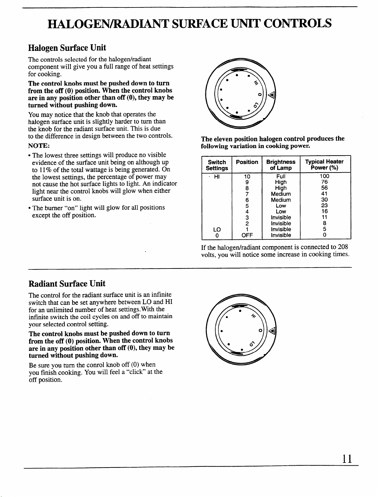
The eleven position halogen control produces the
following variation in cooking power.
Switch
Settings
L HI
Position
10
I
‘: I OFF
1
Brightness
of Lamp
Full
High
High
Medium
Medium
Low
Low
Invisible
Invisible
Invisible
Invisible
Typical Heater
Power
(Yo)
100
76
56
41
30
23
16
11
8
5
0
If the halogen/radiant component is connected to 208
volts, you will notice some increase in cooking times.
Radiant Surface Unit
The control for the radiant surface unit is an infinite
switch that can be set anywhere between LO and HI
for an unlimited number of heat settings.Wxth the
infinite switch the coil cycles on and off to maintain
your selected control setting.
The control knobs must be pushed down to turn
from the off (0) position. When the control knobs
are in any position other than off(0), they may be
turned without pushing down.
Be sure you turn the conrol knob off(0) when
you finish cooking. You will feel a “click” at the
off position.
11
GAS BURNER CONTROLS
See the Gas Burner Component section.
The gas burnercontrols must tum counterclockwise
to the LITE position to ignite the burner.
Once the burner is ignited, turn the control knob
counterclockwise to adjust the flame lower. A
sparking sound caused by the igniter is normal
until ignition occurs.
The burners will relight at any setting. However, for
the burners to light quickly and consistently when the
gas is turned on, the knobs should be turned to the
LITE position until ignition occurs.
When turning the control knob to off (0), turn
it clockwise.
GRILL/GRIDDLECONTROLS
See both the Grill Component and the Griddle
Accessory sections. Also see the Grill Cooking and
the Griddle Cooking Guides.
Most cooking on the ~till or griddle is done at the HI
setting. See the Grill Component section regarding
flame-ups and the control settings for this emergency.
Each half of the grill component is controlled
separately.
The control knob labeled GRIDDLE controls the
entire griddle accessory.
The GRILIJGRIDDLE controls turn either direction
to adjustthe heat setting.
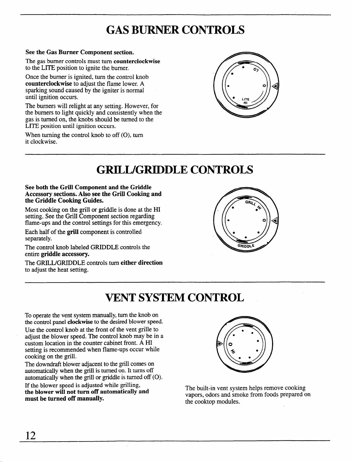
VENT SYSTEM CONTROL
To operate the vent system manually, turn the knob on
the control panel clockwise to the desired blower speed.
Use the control knob at the front of the vent ~tille to
~
●
adjust the blower speed. The control knob may be in a
●
custom location in the counter cabinet front. A HI
Bo” “
setting is recommended when flame-ups occur while
*
●
cooking on the ~till.
●
●
The downdraft blower adjacent to the till comes on
automatically when the ~till is turned on. It turns off
automatically when the ~till or ~tiddle is turned off (0).
If the blower speed is adjusted while ~tilling,
the blower will not turn off automatically and
must be turned off manually.
The built-in vent system helps remove cooking
vapors, odors and smoke from foods prepared on
the cooktop modules.
12
HALOGEN/RADIANT COMPONENT
General Information About Halogen/Radiant Surface Units
The halogen/radiant cooktop features heating units
Use only flat-bottomed cookware. Do not let pots boil
beneath a smooth glass ceramic surface. The surface
dry. Overheated metal can bond to glass cooktop. An
units are shown by outlines on the glass.
overheated copper pot will leave a residue that will
Before you use the cooktop for the first time, clean it
permanently stain the glass.
with Cook Top Cleaning Creme. This helps protect
Sliding aluminum cookware across the glass may
the top and makes clean-up easier. leave metal marks. These metal marks will appear as
NOTE: A slight odor is normal when a new cooktop
small scratches. They can be removed with Cook Top
is used for the first time. It is caused by the heating of
Cleaning Creme and a razor scraper.
new parts and insulating materials and-will disapp&.r It is safe to place hot cookware from the oven or
in a short time. surface on the glass ceramic surface when the surface
When a surface unit is turned on, coils beneath the
is cool.
surface unit radiate heat through the glass to the
cookware. The red glow of the coils will be visible
through the glass. It will take the surface unit a few
moments to heat up. The coil cycles on and off to
maintain your selected control setting. Wkh poor
cookware, you will see frequent cycling of the unit
off and on. Good, flat cookware will minimize
the cycling.
Avoid sliding pans on the glass cooktop. Pan edges
that are even slightly rough or ~tit on the cooktop can
cause scratches on the glass.
Even after the surface units are turned off, the glass
ceramic cooktop retains enough heat to continue
cooking. To avoid overcooking, remove pans from
the surface units when the food is cooked. Avoid
placing anything on the surface unit until it has
cooled completely.
Differences Between Halogen and Radiant Units
Some cooktops have both radiant and halogen surface
units. This is how they differ.
● Halogen units are much brighter than the radiant
units. Radiantunits have a dull red glow.
● Halogen and radiant units cycle on and off
frequently. This is normal. You will notice the
cycling more on the halogen units because of
their brightness.
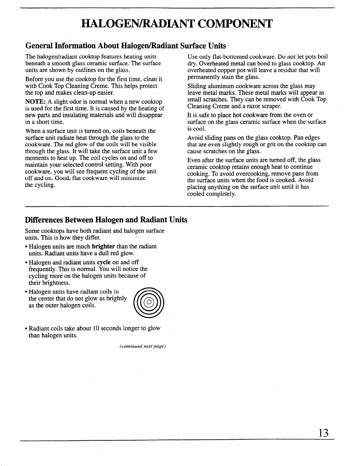
. Halogen units have radiant coils in
the center that do not glow as brightly
as the outer halogen coils.
Q
ozyxwvutsrqponmlkjihgfedcbaZYXWVUTSRQPONMLKJIHGFEDCBA
0
c Radiant coils take about 10 seconds longer to glow
than halogen units.
(continued next page)
13
HALOGEN/R.ADIA.NTCOMPONENT
(continued)
Vpes of Cookware
The following information will help you choose
cookware which will give good performance.
Stainless Steel: highly recommended
Especially good with a sandwich clad bottom. The
sandwich bottom combines the benefits of stainless
steel (appearance, durability and stability) with the
advantages of aluminum or copper (heat conduction,
even heat distribution).
Aluminum: heavy weight recommended
Good conductivity. Aluminum residues sometimes
appear as scratches on the cooktop, but can be
removed if cleaned immediately. Because of its
low melting point, thin weight aluminum should not
be used.
Porcelain/Enamel:
Good performance only with a thick, flat, smooth
bottom. Avoid boiling dry, as porcelain can melt and
fise to the surface.
Copper Bottom: heavy weight recommended
Good performance, but copper may leave residues
which can appear as scratches. The residues can be
removed, as long as the cooktop is cleaned
immediately. However, do not let these pots boil dry.
Overheated metal can bond to glass cooktops.
An overheated copper pot will leave a residue that
will permanently stain the cooktop.
Glass-ceramic: not recommended
Poor performance. May scratch the surface.
Usable, but not recommended.
Stoneware: not recommended
Poor performance. May scratch the surface.
Usable, but not recommended.
Cast Iron: not recommended
Poor performance. May scratch the surface.
Usable, but not recommended.
How to Check Pan Performance
Use of correct cookware can affect the cooking
performance and cleaning of your cooktop.
The correct cookware reduces the temperature of
the cooktop surface and minimizes the chance of
‘L- CF ‘a-
spillovers burning onto the cooktop.
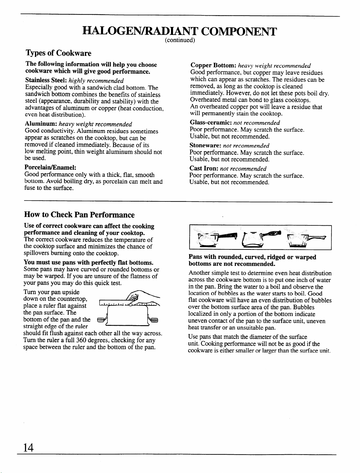
Pans with rounded, curved, ridged or warped
You must use pans with perfectly flat bottoms.
bottoms are not recommended.
Some pans may have curved or rounded bottoms or
may be warped. If you are unsure of the flatness of
your pans you may do this quick test.
Turn your pan upside
down on the countertop,
place a ruler flat against
the pan surface. The
bottom of the pan and the
straight edge of the ruler
should fit flush against each other all the way across.
Turn the ruler a full 360 degrees, checking for any
space between the ruler and the bottom of the pan.
Another simple test to determine even heat distribution
across the cookware bottom is to put one inch of water
in the pan. Bring the water to a boil and observe the
location of bubbles as the water starts to boil. Good
flat cookware will have an even distribution of bubbles
over the bottom surface area of the pan. Bubbles
localized in only a portion of the bottom indicate
uneven contact of the pan to the surface unit, uneven
heat transfer or an unsuitable pan.
Use pans that match the diameter of the surface
unit. Cooking performance will not be as good if the
cookware is either smaller or larger than the surface unit.
14
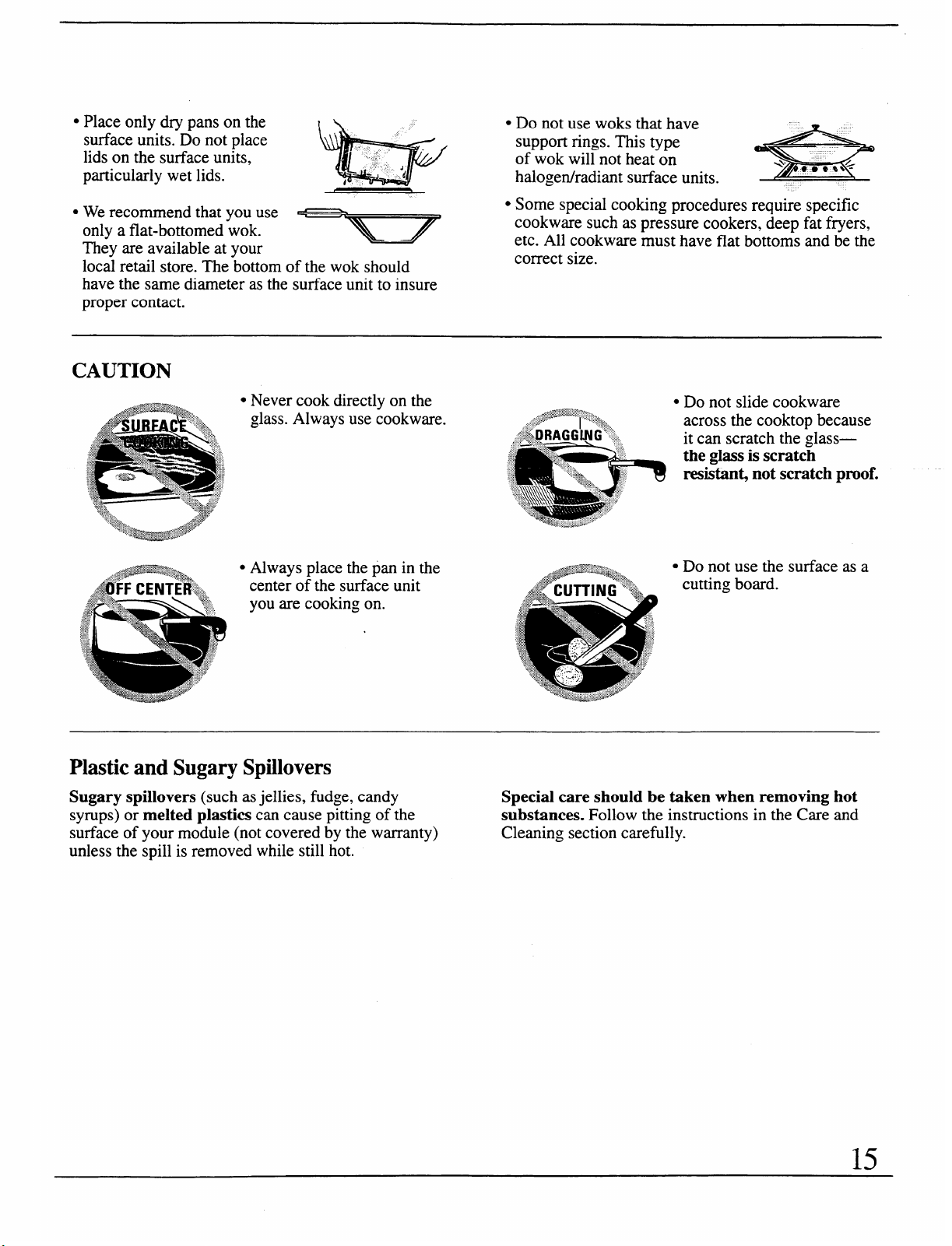
● Place only @ pans on the
surface units. Do not place
lids on the surface units,
particularly wet lids.
s We recommend that you use
only a flat-bottomed wok.
They are available at your
local retail store. The bottom of the wok should
have the same diameter as the surface unit to insure
proper contact.
● Do not use woks that have
support rings. This type
of wok will not heat on
halogenhadiant surface units.
*
● Some special cooking procedures require specific
cookware such as pressure cookers, deep fat fryers,
etc. All cookware must have flat bottoms and be the
correct size.
CAUTION
Never cook directly on the ● Do not slide cookware
,.+~~~<’,....
glass. Always use cookware.
.,<,.++
-\“2*4
. ,.,
J,
across the cooktop because
,/_,DRAGGING”” ~
it can scratch the glass—
‘,
%+
..,.
,,J
:.
,.,
the gkss is scratch
-,...
.&
‘‘::$.’,.”,.,
resistanqnot scratch proof.
..
M
.*”<,
,>+
.. .’
“..>
t. .>
/7, ,
>,.
~?
.L
““%.kkk,&_>P..“
Plastic and Sugary Spillovers
Sugary spillovers (such as jellies, fudge, candy
Special care should be taken when removing hot
syrups) or melted plastics can cause pitting of the
substances. Follow the instructions in the Careand
surface of your module (not covered by the warranty)
Cleaning section carefully.
unless the spill is removed while still hot.
15
HOME C
A.NNINGTIPS
Canning cannot be done on the grill or griddle components.
Observe the Following Points in Canning
1. Be sure the canner fits over the center of the
surface unit. If your range or its location does not
aIlow the canner to be centered on the surface unit,
use smaller diameter pots for good canning results.
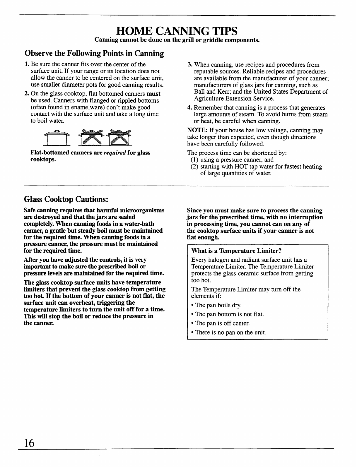
2. On the glass cooktop, flat bottomed canners must
be used. Canners with flanged or rippled bottoms
(often found in enamelware) don’t make good
contact with the surface unit and take a long time
to boil water.
Flat-bottomed canners are required for glass
cooktops.
3. When canning, use recipes and proceduresfrom
reputablesources. Reliable recipes and procedures
areavailable from the manufacturerof your canner;
manufacturersof glass jars for canning, such as
Ball and Kerr;and the United States Departmentof
AgricultureExtension service.
4. Remember that canning is a process that generates
l~ge amounts of steam. To avoid burns from steam
or heat, be careful when canning.
NOTE: If your house has low voltage, canning may
take longer than expected, even though directions
have been carefully followed.
The process time can be shortened by:
(1)
using a pressure canner, and
(2) starting with HOT tap water for fastest heating
of large quantities of water.
Glass Cooktop Cautions:
Safe canning requires that harmful microorganisms
Since you must make sure to process the canning
are destroyed and that the jars are sealed
jars for the prescribed time, with no interruption
completely. When canning foods in a water-bath in processing time, you cannot can on any of
canner, a gentle but steady boil must be maintained
the cooktop surface units if your canner is not
for the required time. When canning foods in a
flat enough.
pressure canner, the pressure must be maintained
t
for the required time.
After you have adjusted the controls, it is very
important to make sure the prescribed boil or
pressure levels are maintained for the required time.
The glass cooktop surface units have temperature
limiters that prevent the glass cooktop from getting
too hot. If the bottom of your canner is not flat, the
surface unit can overheat, triggering the
temperature limiters to turn the unit off for a time.
This will stop the boil or reduce the pressure in
the canner.
What is a Temperature Limiter?
Every halogen and radiant surface unit has a
Temperature Limiter. The Temperature Limiter
protects the glass-ceramic surface from getting
too hot.
The Temperature Limiter may turn off the
elements ifi
● The pan boils dry.
. The pan bottom is not flat.
. The pan is off center.
● There is no pan on the unit.
16
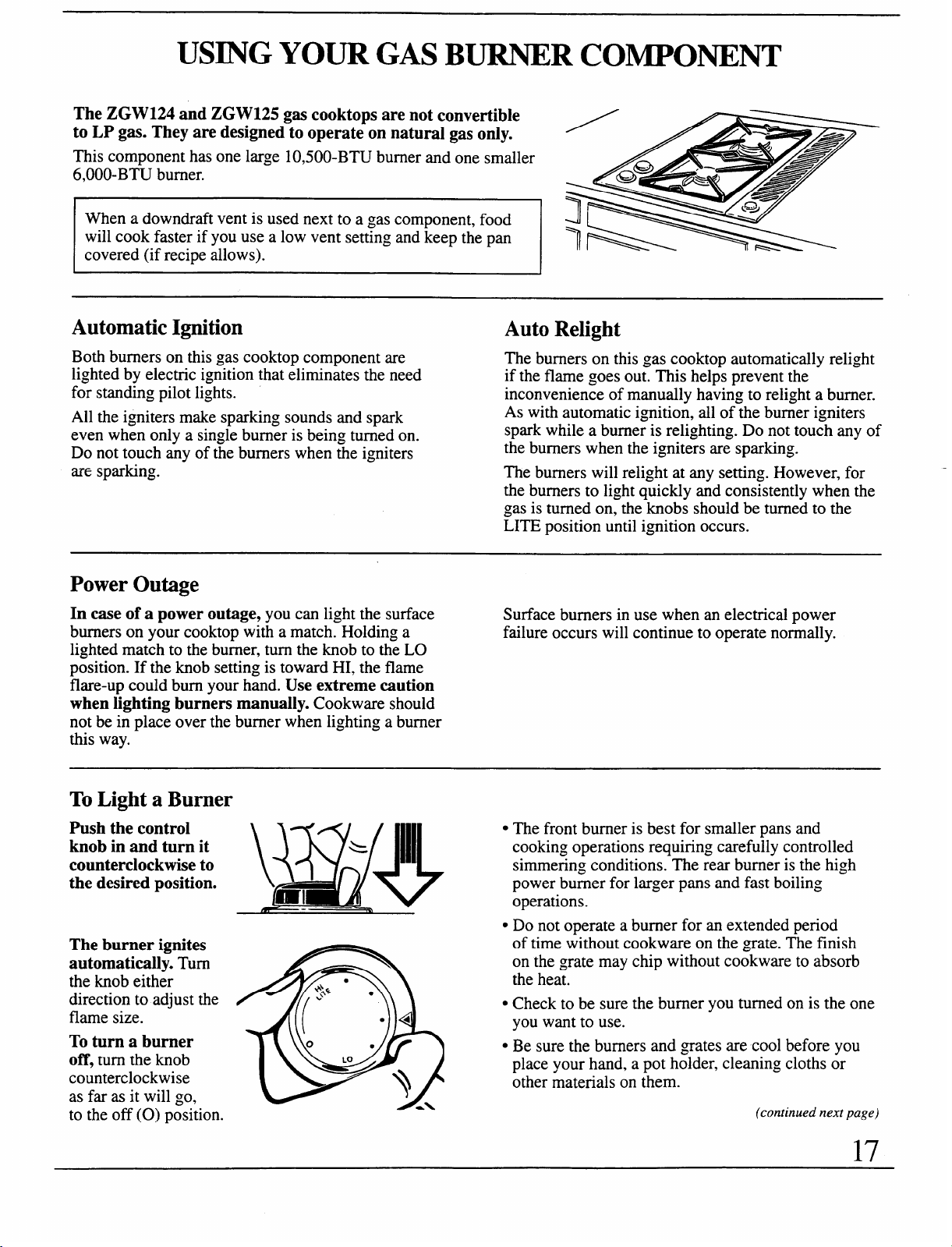
USINGYOUR GAS BURNER COMPONENT
The ZGW124 and ZGW125 gas cooktops are not convertible
to LP gas. They are designed to operate on natural gas only.
This component has one large 1O,5OO-BTUburner and one smaller
6,000-BTU burner.
When a downdraft vent is used next to a gas component, food
will cook faster if you use a low vent setting and keep the pan
covered (if recipe allows).
Automatic Ignition
Both burners on this gas cooktop component are
lighted by electric ignition that eliminates the need
for standing pilot lights.
All the igniters make sparking sounds and spark
even when only a single burner is being turned on.
Do not touch any of the burners when the igniters
are sparking.
Auto Relight
The burners on this gas cooktop automatically relight
if the flame goes out. This helps prevent the
inconvenience of manually having to relight a burner.
As with automatic ignition, all of the burner igniters
spark while a burner is relighting. Do not touch any of
the burners when the igniters are sparking.
The burners will relight at any setting. However, for
the burners to light quickly and consistently when the
gas is turned on, the knobs should be turned to the
LITE position until ignition occurs.
Power Outage
In case of a power outage, you can light the surface
Surface burners in use when an electrical power
burners on your cooktop with a match. Holding a
failure occurs will continue to operate normally.
lighted match to the burner, turn the knob to the LO
position. If the knob setting is toward HI, the flame
flare-up could bum your hand. Use extreme caution
when lighting burners manually. Cookware should
not be in place over the burner when lighting a burner
this way.
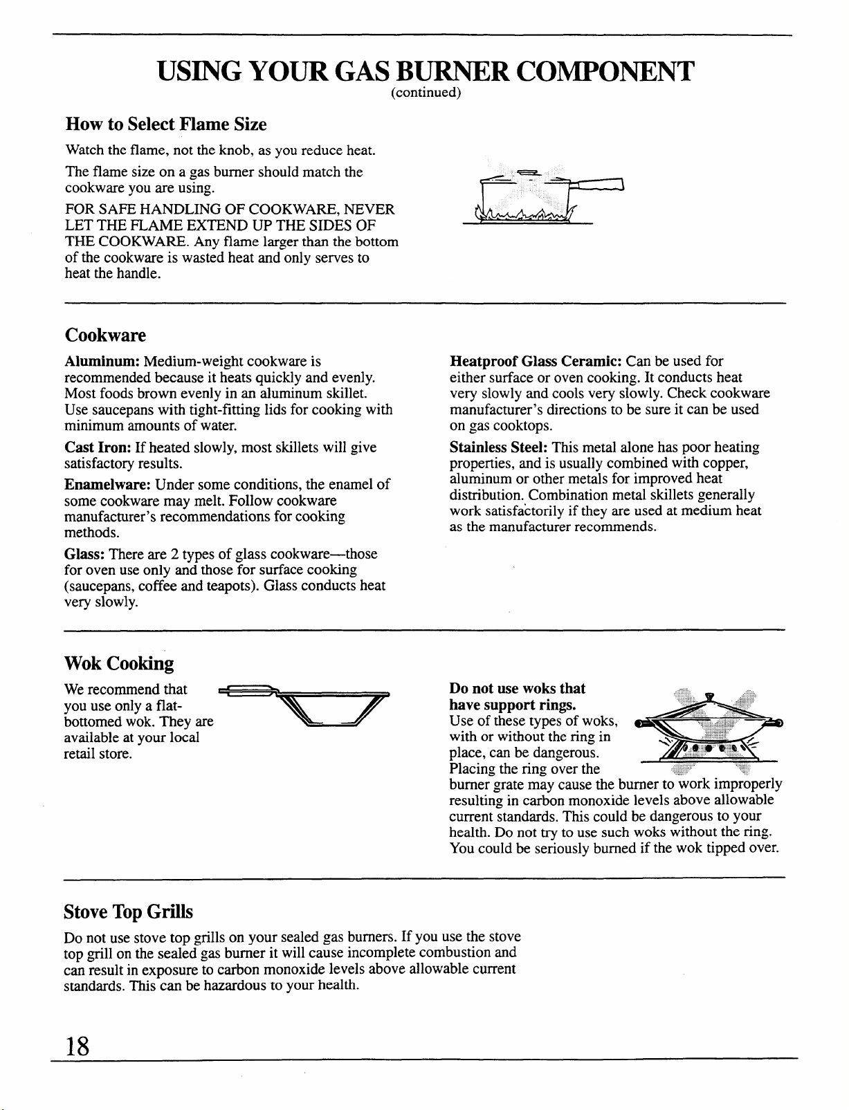
To Light a Burner
Push the control
knob in and turn it
counterclockwise to
the desired Dosition.
\~’;/~,~~,
The burner ignites
automatically. Turn
the knob either
direction to adjust the
flame size.
To turn a burner
off, turn the knob
counterclockwise
as far as it will go,
to the off (0) position.
c The front burner is best for smaller pans and
cooking operations requiring carefully controlled
simmering conditions. The rear burner is the high
power burner for larger pans and fast boiling
operations.
● Do not operate a burner for an extended period
of time without cookware on the grate. The finish
on the grate may chip without cookware to absorb
the heat.
. Check to be sure the burner you turned on is the one
you want to use.
. Be sure the burners and grates are cool before you
place your hand, a pot holder, cleaning cloths or
other materials on them.
(continued next page)
17
USING YOUR GAS BURNER COMPONENT
(continued)
How to Select Flame Size
Watch the flame, not the knob, as you reduce heat.
The flame size on a gas burner should match the
cookware you are using.
FOR SAFE HANDLING OF COOKWARE, NEVER
LET THE FLAME EXTEND UP THE SIDES OF
THE COOKWARE. Any flame larger than the bottom
of the cookware is wasted heat and only serves to
heat the handle.
Cookware
Aluminum: Medium-weight cookware is
recommended because it heats quickly and evenly.
Most foods brown evenly in an aluminum skillet.
Use saucepans with tight-fitting lids for cooking with
minimum amounts of water.
Cast Iron: If heated slowly, most skillets will give
satisfactory results.
Enamelware: Under some conditions, the enamel of
some cookware may melt. Follow cookware
manufacturer’s recommendations for cooking
methods.
Glass: There are 2 types of glass cookware-those
for oven use only and those for surface cooking
(saucepans, coffee and teapots). Glass conducts heat
very slowly.
Heatproof Glass Ceramic: Can be used for
either surface or oven cooking. It conducts heat
very slowly and cools very slowly. Check cookware
manufacturer’s directions to be sure it can be used
on gas cooktops.
Stainless Steel: This metal alone has poor heating
properties,and is usually combined with copper,
aluminum or othermetals for improved heat
distribution.Combination metal skillets generally
work satisfactorily if they are used at medium heat
as the manufacturer recommends.
Wok Cooking
We recommend that
you use only a flat-
bottomed wok. They are
available at your local
retail store.
Do not use woks that
have support rings.
Use of these types of woks,
with or without the ring in
place, can be dangerous.
Placing the ring over the
bume{grate may cause the burner to work improperly
resultin~ in carbon monoxide levels above allowable
current &mdards. This could be dangerous to your
health. Do not try to use such woks without the ring.
You could be seriously burned if the wok tipped over.
Stove Top Grills
Do not use stove top grills on your sealed gas burners. If you use the stove
top grill on the sealed gas burner it will cause incomplete combustion and
can result in exposure to carbon monoxide levels above allowable current
standards. This can be hazardous to your health.
18
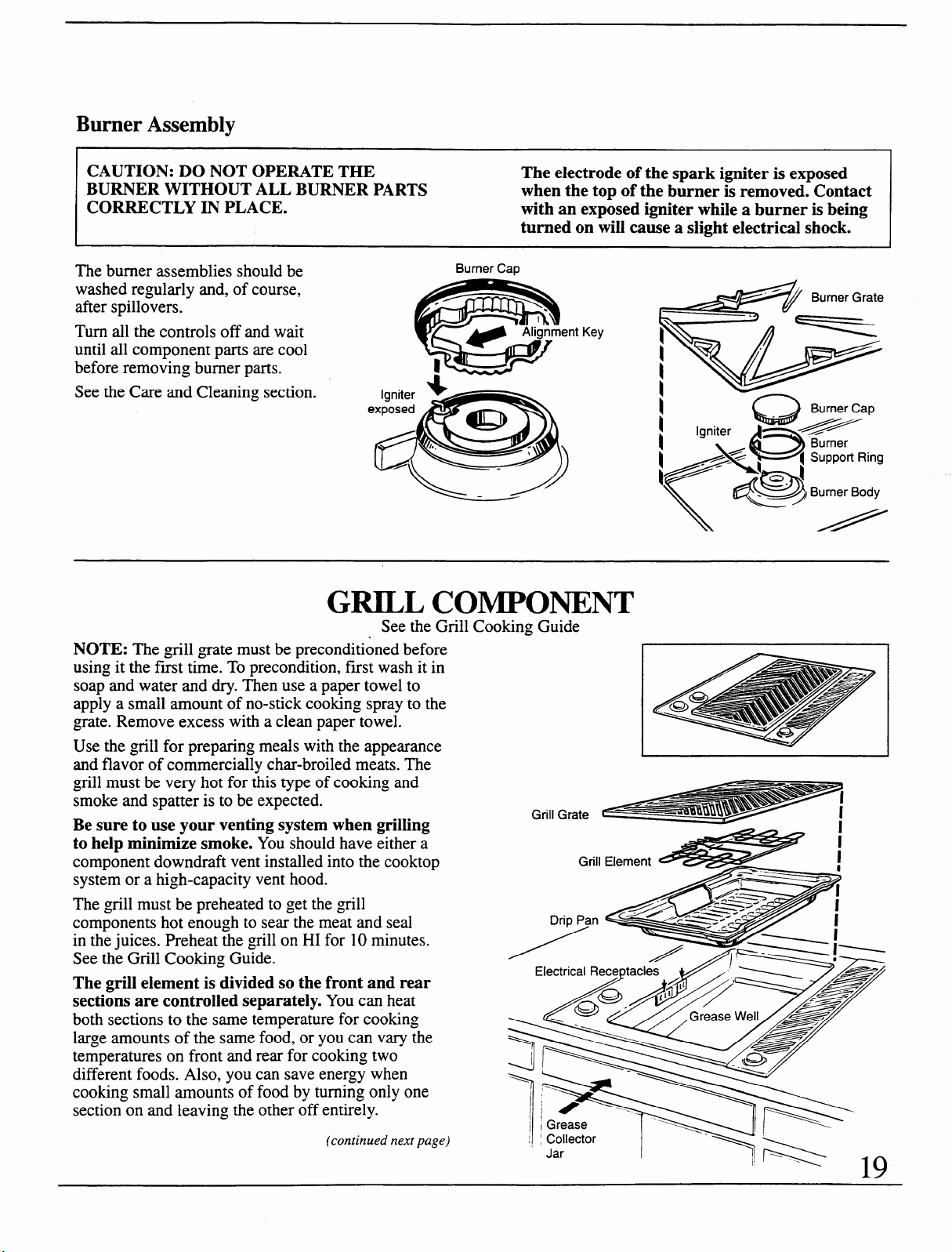
Burner Assembly
CAUTION: DO NOT OPERATE THE
The electrode of the spark igniter is exposed
BURNER WITHOUT ALL BURNER PARTS
when the top of the burner is removed. Contact
CORRECTLY IN PLACE.
with an exposed igniter while a burner is being
turned on will cause a slight electrical shock.
The burner assemblies should be
washed regularly and, of course,
afier spillovers.
Turn all the controls off and wait
until all component parts are cool
before removing burner parts.
See the Care and Cleaning section.
Burner Cap
=————=.
.
fg?i!?’
e
Alignment Key
m
Igniter
s
exposed
—
Q
Burner Cap
.//==
\
//
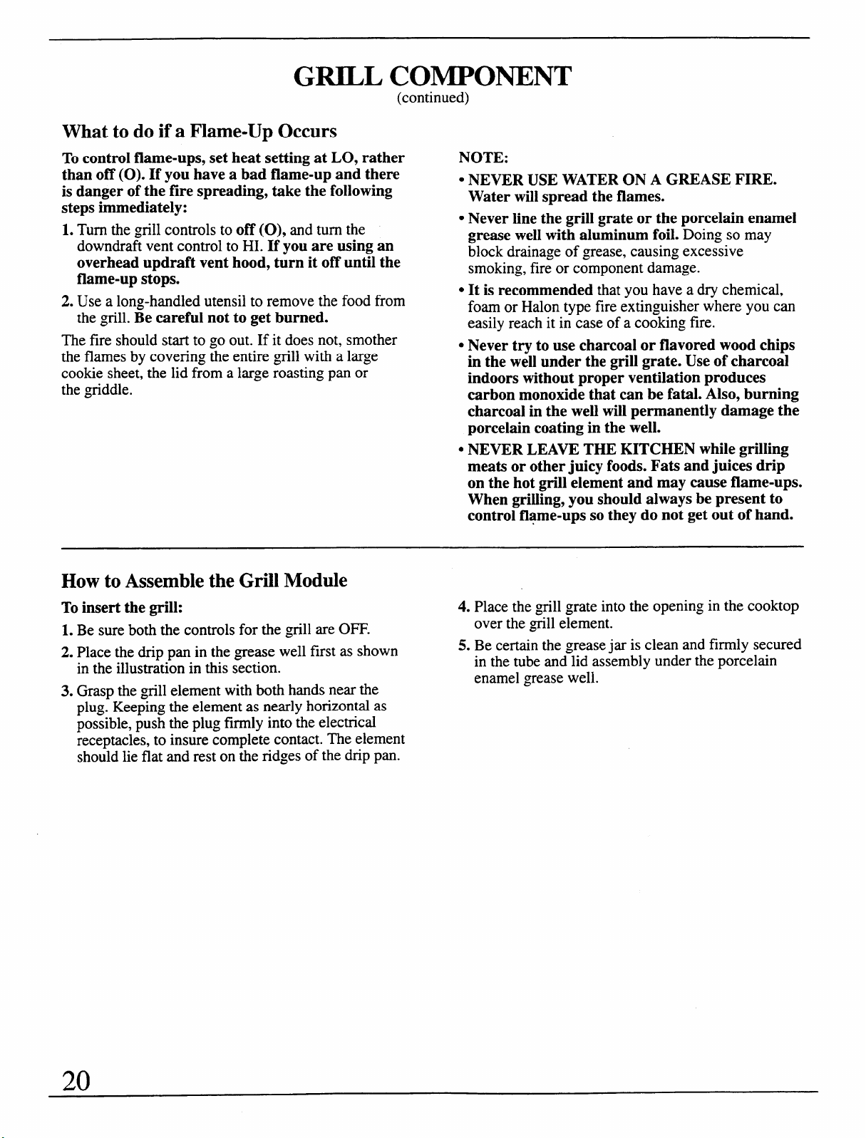
GRILL COMPONENT
See the Grill Cooking Guide
NOTE: The grill grate must be preconditioned before
using it the first time. To precondition, first wash it in
soap and water and dry. Then use a paper towel to
apply a small amount of no-stick cooking spray to the
grate. Remove excess with a clean paper towel.
Use the grill for preparing meals with the appearance
and flavor of commercially char-broiled meats. The
OriHmust be very hot for this type of cooking and
a
smoke and spatter is to be expected.
Be sure to use your venting system when grilling
to help minimize smoke. You should have either a
component downdraft vent installed into the cooktop
system or a high-capacity vent hood.
The grill must be preheated to get the ~till
components hot enough to sear the meat and seal
in the juices. Preheat the grill on HI for 10 minutes.
See the Grill Cooking Guide.
The grill element is divided so the front and rear
sections are controlled separately. You can heat
both sections to the same temperature for cooking
large amounts of the same food, or you can VaIYthe
temperatures on front and rear for cooking two
different foods. Also, you can save energy when
cooking small amounts of food by turning only one
section on and leaving the other off entirely.
Grill Grate
Grill Element 4?
Drh Pan <
Electrical RecerXacles ~=,’ ~ ~/Z2
(continued next page)
Jar
I
GRILL COMPONENT
(continued)
What to do if a Flame-Up Occurs
To control flame-ups, set heat setting at LO, rather
than off (0). If you have a bad flame-up and there
is danger of the fire spreading, take the following
steps immediately:
1. Turn the grill controls to off (0), and turn the
downdraft vent control to HI. If you are using an
overhead updraft vent hood, turn it off until the
flame-up stops.
2. Use a long-handled utensil to remove the food from
the grill. Be careful not to get burned.
NOTE:
c NEVER USE WATER ON A GREASE FIRE.
Water will spread the flames.
QNever line the grill grate or the porcelain enamel
grease well with aluminum foil. Doing so may
block drainageof grease, causing excessive
smoking, fire or component damage.
● It is recommended that you have a dry chemical,
foam or Halon type fire extinguisher where you can
easily reach it in case of a cooking fire.
The fire should start to go out. If it does not, smother
● Never try to use charcoal or flavored wood chips
the flames by covering the entire grill with a large
in the well under the grill grate. Use of charcoal
cookie sheet, the lid from a large roasting pan or
indoors without proper ventilation produces
the griddle.
carbon monoxide that can be fatal. Also, burning
charcoal in the well will permanently damage the
porcelain coating in the well.
c NEVER LEAVE THE KITCHEN while grilling
meats or other juicy foods. Fats and juices drip
on the hot grill element and may cause flame-ups.
When grilling, you should always be present to
control flame-ups so they do not get out of hand.
How to Assemble the Grill Module
To insert the grill:
4. Place the grill grate into the opening in the cooktop
1. Be sure both the controls for the grill are OFF.
over the ~till element.
2. Place the drip pan in the ~wase well first as shown
5. Be certain the grease jar is clean and firmly secured
in the illustration in this section.
in the tube and lid assembly under the porcelain
3. Grasp the till element with both hands near the
enamel grease well.
plug. Keeping the element as nearly horizontal as
possible, push the plug firmly into the electrical
receptacles, to insure complete contact. The element
should lie flat and rest on the ridges of the drip pan.
20
Grill Tips
. Do not leave grill unattended while it is in use.
“ Use the ~gill ONLY with the downdraft vent blower
on HI to carry away smoke and fumes.
. Remove accumulated grease from the non-
removable grease well after each use to lessen
smoking and odors. Be sure opening to grease tube
is clean. Grease buildup can become a fire hazard.
● Make sure the removable grease collector jar and
drip pan are clean and in place before using the grill.
QRemove ~~ease from the grease collector jar after
each use to avoid spillovers.
c The grates should be oiled or sprayed with a non-
stick coating before cooking to prevent sticking.
Remove the grate before spraying and spray only
while cool. Spraying directly onto a hot grill may
cause a fire.
. Preheat the grill for 10 minutes at HI heat setting,
then turn to the desired setting for cooking.
● Trim the fat from meat before placing on the ~grill.
This will reduce smoking and lessen grease buildup
in the drip pan, grease well and grease jar.
● Allow space between foods when placing them on
the grill. Air and heat need to circulate around the
food for best cooking results.
. Occasionally rearrange foods on the grill to prevent
sticking and provide better browning.
. A griddle accessory can be purchased from
your dealer to utilize the ~grillcomponent’s
griddle capacity.
Questions and Answers
Q. When cooking many individual foods, what can
I do to insure that foods will cook evenly?
A. When cooking foods of various sizes and
thicknesses, start larger or thicker pieces first and
add quicker-cooking smaller pieces later. Press
meat lightly to lie flat on grill. Slash the fat on
edges of steaks and chops to prevent curling.
Break the joints of split chickens so they will
lie flat.
Q. My grilled meats sometimes come out drier than
they should. What can I do to help prevent this?
A. Season meats after cooking rather than
before—salt can draw out juices and dry out meat.
Use tongs to turn and reamange meats on the grill;
forks will pierce the meat and release juices.
Q. I follow the cooking times suggested, but my
foods don’t get done properly. Is there
something wrong with my grill?
A. Probably not. Suggested cooking times should be
used only as a general guide. Variables in food can
change the cooking times required.
Q. How can I keep barbecued meats from
developing an unattractive burned look
and taste?
A. Sauces containing sugar will often bum if used
during the entire cooking time. If your favorite
sauce contains sugar, try adding it only during the
last 15 to 20 minutes of cooking time for best
results.
Q. Foods cooked on my grill are not browning as
much as I would like. What could cause this?
A. A longer preheating and ~till time maybe
necessary to achieve the desired results.
21
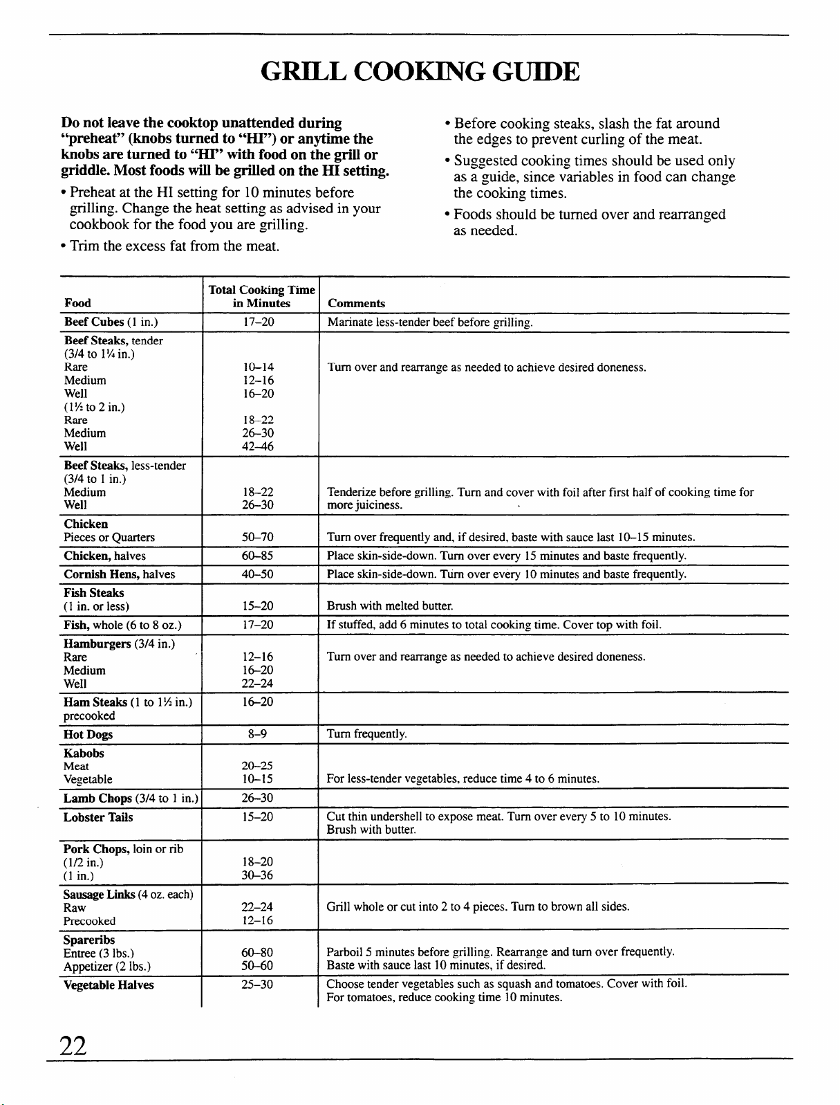
GRILL COOKING GUIDE
Do not leave the cooktop unattended during
. Before cooking steaks, slash the fat around
“preheat>>(knobs turned to ‘W.P7)or anytime the
the edges to prevent curling of the meat.
knobs are turned to “HI” with food on the grill or
griddle. Most foods will be grilled on the HI setting.
. Suggested cooking times should be used only
as a guide, since variables in food can change
QPreheat at the HI setting for 10 minutes before
the cooking times.
grilling. Change the heat setting as advised in your
cookbook for the food you are ~tilling.
. Foods should be turned over and rearranged
as needed.
QTrim the excess fat from the meat.
Total Cooking Time
in MinutesFood
Comments
Beef Cubes (1
in.)
17-20 Marinate less-tender beef before =tilling.
Beef Steaks, tender
(3/4 to 1% in.)
Rare
Medium
Well
(l?4t02 in.)
Rare
Medium
Well
10-14
12–16
16-20
18-22
26-30
42-46
Turn over and rearrange as needed to achieve desired doneness.
Beef Steaks, less-tender
(3/4 to 1 in.)
Medium
Well
18–22
26-30
Tenderize before grilling. Turn and cover with foil after first half of cooking time for
more juiciness.
Chicken
Pieces or Quarters 50-70 Turn over frequently and, if desired, baste with sauce last 10-15 minutes.
Chicken, halves 60-85
Place skin-side-down. Turn over every 15 minutes and baste frequently.
Cornish Hens, halves
40-50 Place skin-side-down. Turn over every 10 minutes and baste frequently.
Fish Steaks
(1 in. or less)
15-20 Brush with melted butter.
Fish, whole (6 to 8 oz.)
17–20
If stuffed, add 6 minutes to total cooking time. Cover top with foil.
Hamburgers (3/4 in.)
Rare
Medium
Well
12–16
16-20
22-24
Turn over and rearrange as needed to achieve desired doneness.
Ham Steaks (1 to 1!4 in.)
precooked
1G20
8-9
Turn frequently.
Hot DOIW
Kabobs
Meat
Vegeuble
20-25
10-15
For less-tender vegetables, reduce time 4 to 6 minutes.
26-30
Lamb Chops (3/4 to 1 in.)
Lobster Tails
15–20
Cut thin undersell to expose meat. Turn over every 5 to 10 minutes.
Brush with butter.
18–20
30-36
22–24
12–16
60-80
50-60
25-30
Pork Chops, loin or rib
(1/2 in.)
(1 in.)
Sausage Links (4 oz. each)
Raw
Precooked
Grill whole or cut into 2 to 4 pieces. Turn to brown all sides.
Spareribs
Entree (3 lbs.)
Appetizer (2 Ibs.)
Parboil 5 minutes before grilling. Rearrange and turn over frequently.
Baste with sauce last 10 minutes, if desired.
Vegetable Halves
Choose tender vegetables such as squash and tomatoes. Cover with foil.
I
For tomatoes, red;ce cooking time i O minutes.
22
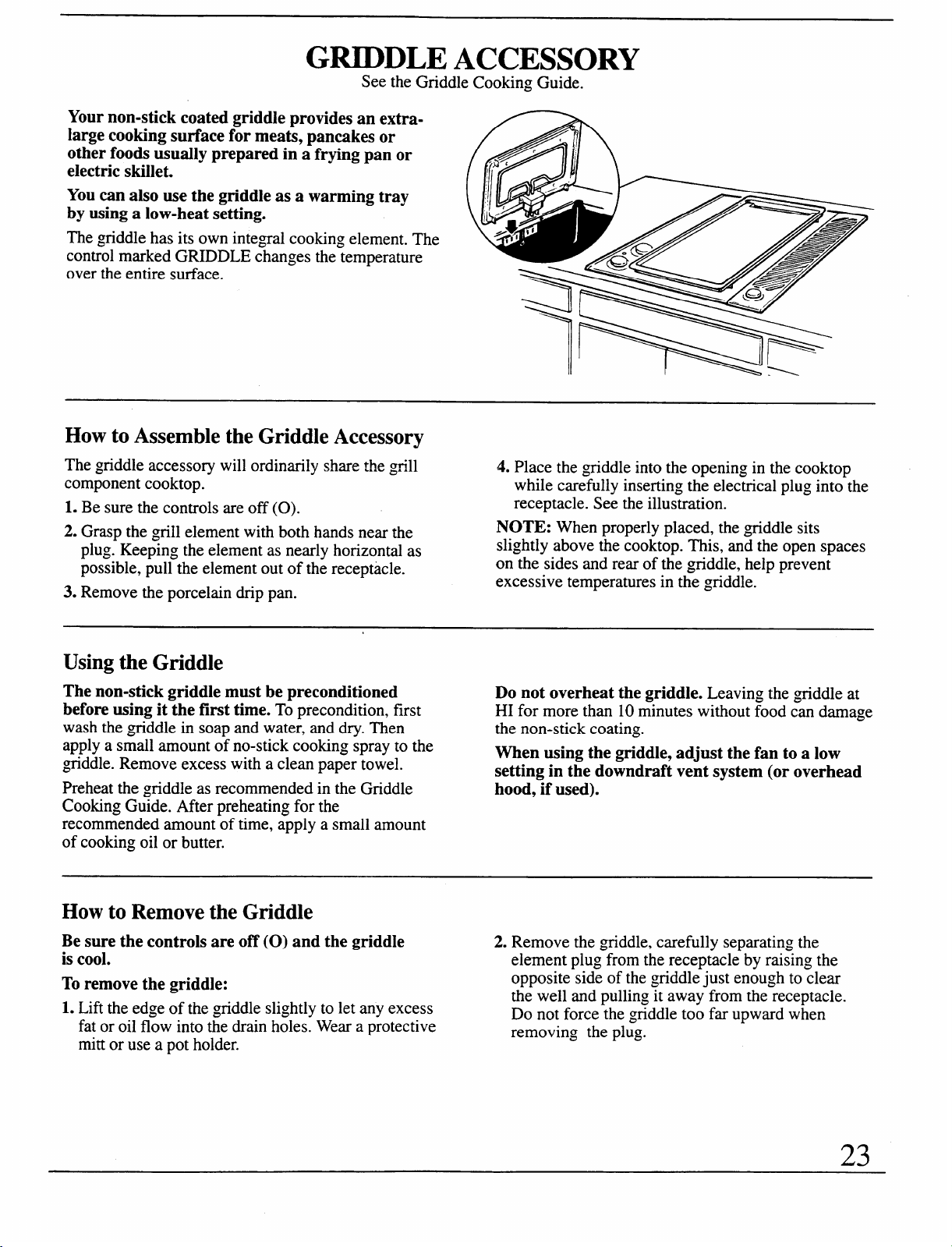
GRIDDLE ACCESSORY
See the Griddle Cooking Guide.
Your non-stick coated griddle provides an extra-
large cooking surface for meats, pancakes or
other foods usually prepared in a frying pan or
electric skillet.
You can also use the griddle as a warming tray
by using a low-heat setting.zyxwvutsrqponmlkjihgfedcbaZYXWVUTSRQPONMLKJIHGFEDCBA
megriddlezyxwvutsrqponmlkjihgfedcbaZYXWVUTSRQPONMLKJIHGFEDCBAhas its own integal cooking element- The
control marked GRIDDLE changes the temperature
over the entire surface.
How to Assemble the Griddle Accessory
The griddle accessory will ordinarily share the grill
component cooktop.
1. Be sure the controls are off (0).
2. Grasp the grill element with both hands near the
plug. Keeping the element as nearly horizontal as
possible, pull the element out of the receptacle.
3. Remove the porcelain drip pan.
4. Place the ~giddle into the opening in the cooktop
while carefully inserting the electrical plug into the
receptacle. See the illustration.
NOTE: When properly placed, the griddle sits
slightly above the cooktop. This, and the open spaces
on the sides and rear of the griddle, help prevent
excessive temperatures in the griddle.
Using the Griddle
The non-stick griddle must be preconditioned
before using it the first time. To precondition, first
wash the ~tiddle in soap and water, and dry. Then
apply a small amount of no-stick cooking spray to the
griddle. Remove excess with a clean paper towel.
Preheat the griddle as recommended in the Griddle
Cooking Guide. After preheating for the
recommended amount of time, apply a small amount
of cooking oil or butter.
Do not overheat the griddle. Leaving the griddle at
HI for more than 10 minutes without food can damage
the non-stick coating.
When using the griddle, adjust the fan to a low
setting in the downdraft vent system (or overhead
hood, if used).
How to Remove the Griddle
Be sure the controls are off (0) and the griddle
2. Remove the griddle, carefully separating the
is cool.
element plug from the receptacle by raising the
To remove the griddle:
opposite side of the griddle just enough to clear
the well and pulling it away from the receptacle.
1. Lift the edge of the griddle slightly to let any excess
Do not force the griddle too far upward when
fat or oil flow into the drain holes. Wear a protective
removing the plug.
mitt or use a pot holder.
23
GRIDDLE ACCESSORY
(continued)
Griddle Tips
● Condition or “season” griddle before first-time use.
● Most griddled foods are those that require cooking
on a preheated surface. The ~tiddle surface may be
Oreased lightly before adding food. Preheat the
&
griddle 5 minutes at HI heat setting, unless
otherwise indicated in the Griddle Cooking Guide,
then switch to the recommended cook setting.
. Foods which are high in natural fat, such as bacon or
sausage, may be started on a cold ~tiddle.
● Foods to be warmed may be placed directly on the
griddle; a high-domed metal cover, such as an
inverted metal mixing bowl, placed over them will
help store the heat. Foods in covered dishes or pans
may also be warmed on the griddle. Use heat-
resistant dishes only.
● Make sure the grease collector jar and drip pan are
clean before using the griddle.
● To preserve the finish, use only Teflon@ coated,
nylon or wooden spatulas and spoons. Never use
the griddle surface as a cutting board.
. Over a period of time, minor scratches and some
discoloration may appear in the non-stick coating.
This will not affect the cooking performance or the
non-stick finish.
. Avoid using metal utensils with sharp points or
rough or sharp edges which might damage the
non-stick coated griddle surface. Do not cut foods
on the griddle.
Questions and Answers
Q. How should I store my griddle when it is not
in use?
A. To avoid marring the non-stick finish, store griddle
upright on the edge with the terminals up to avoid
damage. If it is necessary to store it flat, avoid
placing other pans or cookware on top.
Q. Why aren’t my foods done even though they
have cooked the full time?
A. Preheat the griddle for a longer time and leave
foods on the griddle longer to attain the desired
degree of browning.
Q. How long can foods be kept warm with the
griddle without losing their appeal?
A. No longer than 2 hours is recommended, to assure
good food quality and to prevent spoilage. Delicate
foods, such as eggs, should not be kept more than
15 to 30 minutes; entrees and casseroles maybe
warmed for 30 to 60 minutes. Hors d’oeuvres will
stay hot for serving up to 1 or 1!4hours. Rearrange
or stir foods occasionally, if possible.
Q. Do I need special cookware for use with
my griddle?
A. Avoid using metal cookware with sharp points or
rough or sharp edges which might damage the non-
stick-coated griddle surface. Do not cut foods on the
~tiddle. Use only heat-resistant dishes when foods
in containers are to be warmed on the ~giddle. For
further information on caring for your ~tiddle’s
surface, see the Care and Cleaning section.
Q. Can prolonged periods of high heat damage
my griddle% surface?
A. A brief preheating period is often necessary for
best results with many foods, but leaving the
griddle on HI heat setting for more than 1()
minutes without food can damage the non-stick
coating. Always be sure to turn control knobs to
off (0) when cooking is completed.
24
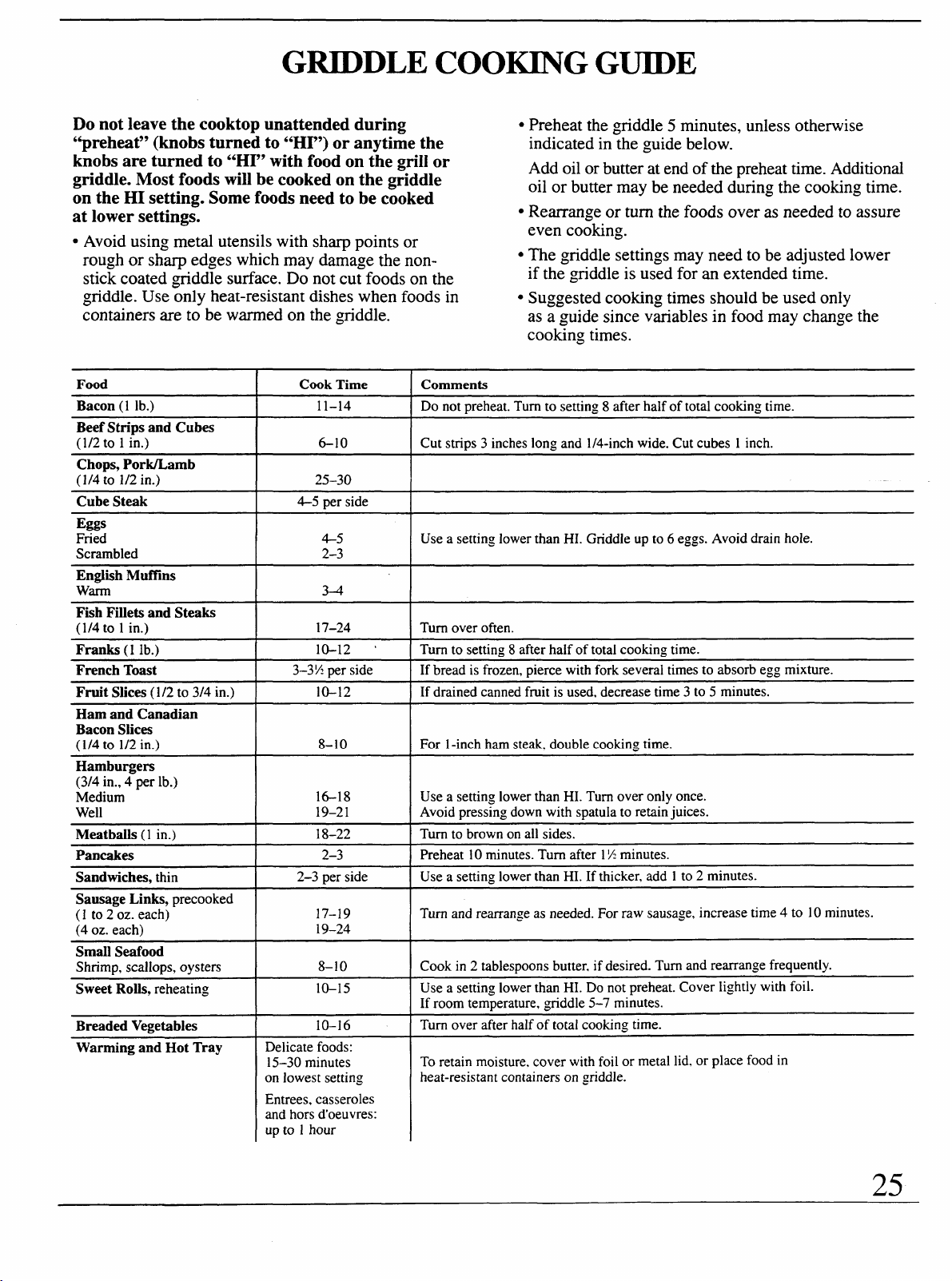
GRIDDLE COOKING GUIDE
Do not leave the cooktop unattended during
“preheat” (knobs turned to “HI”) or anytime the
knobs are turned to “HI” with food on the griil or
griddle. Most foods will be cooked on the griddle
on the HI setting. Some foods need to be cooked
at lower settings.
● Preheat the griddle 5 minutes, unless otherwise
indicated in the guide below.
Add oil or butter at end of the preheat time. Additional
oil or butter may be needed during the cooking time.
● Rearrange or turn the foods over as needed to assure
even cooking.
. Avoid using metal utensils with sharp points or
rough or sharp edges which may damage the non-
stick coated griddle surface. Do not cut foods on the
griddle. Use only heat-resistant dishes when foods in
containers are to be warmed on the griddle.
. The griddle settings may need to be adjusted lower
if the ~tiddle is used for an extended time.
. Suggested cooking times should be used only
as a guide since variables in food may change the
cooking times.
Food
I
Cook Time ] Comments
Bacon (1 lb.)
I
11-14
]zyxwvutsrqponmlkjihgfedcbaZYXWVUTSRQPONMLKJIHGFEDCBADO not preheat.Turn to settirw 8 after half of total cookin.q time.
Beef Strips and Cubes
(1/2 to 1 in.)
I
6-1o
I
Cut strips 3 inches long and 1/4-inch wide. Cut cubes 1 inch.
Chops, Pork/Lamb
(1/4 to 1/2 in.) 25-30
Cube Steak
I
4-5 per side
I
Eggs
Fried
Scrambled
4-5
2-3
Use a setting lower than HI. Griddle up to 6 eggs. Avoid drain hole.
English Muffins
warm
34
‘1
Fkh Fillets and Steaks
(1/4 to 1 in.)
17–24 Turn over often.
Franks (1 lb.)
10-12 ‘ Turn to setting 8 after haif of total cooking time.
French Toast 3–3!4 per side
If bread is frozen, pierce with fork several times to absorb egg mixture.
Fruit Slices (1/2 to 3/4 in.)
10-12 If drained canned fruit is used, decrease time 3 to 5 minutes.
Ham and Canadian
Bacon Slices
(1/4 to 1/2 in.)
Hamburgers
(3/4 in., 4 per lb.)
Medium
Well
Meatballs (1
in.)
8-10
For 1-inch ham steak, double cooking time.
16-18
19–2 1
Use a setting lower than HI. Turn over only once.
Avoid pressing down with spatula to retain juices.
Turn to brown on all sides.18-22
Pancakes
2-3
Preheat 10 minutes. Turn after 1X minutes.
Sandwiches, thin
2–3 per side Use a settinsz lower than HI. If thicker, add 1 to 2 minutes.
Sausage Links, precooked
(1 to 2 oz. each)
(4 oz. each)
Turn and rearrange as needed. For raw sausage, increase time 4 to 10 minutes.
17-19
19-24
Small Seafood
Shrimp, scallops, oysters
Cook in 2 tablespoons butter. if desired. Turn and rearrange frequently.
Use a setting lower
than HI. Do not preheat. Cover lightly with foil.
If room temperature, ~tiddle 5-7 minutes.
Turn over after half of total cooking time.
8-10
10-15
Sweet Rolls, reheating
Breaded Vegetables
10-16
Warming and Hot Tray
Delicate foods:
15–30 minutes
on lowest setting
To retain moisture. cover with foil or metal lid. or place food in
heat-resistant containers on griddle.
Entrees, casseroles
and hors d’oeuvres:
up to 1 hour
25
CARE AND CLEANING
Proper care and cleaning are important so your
BE SURE ELECTRICAL POWER IS OFF
Component Cooktop System will give you efficient
BEFORE CLEANING ANY COMPONENTS.
and satisfactory service. Follow these directions
carefully to help assure safe and proper maintenance.
Care of Components
Some of the components must be cured or
Components and accessories should be cleaned
preconditioned before using them for the
after each use. The longer a soil remains, the harder
first time.
it is to clean. See each component’s section in this
guide for specific instructions.
Brushed Stainless Steel Finish
Wash with soap and water. For heavy soils, first cover
with a damp cloth and let soak 30 minutes. A stainless
steel cleaner may be used.
To remove fingerprints, apply a little baby oil or
cooking oil with a cloth or paper towel. Rub in the
same direction as the brush marks in the stainless
steel finish.
Cleaning methods described above may prove
ineffective. Stubborn baked-on food residue or stains
on the stainless steel surfaces can be removed by
using pad-type oven cleaners. For your safety, use
extreme caution. Oven cleaners are caustic and can
damage or discolor most other surfaces.
Do not use spray-type oven cleaners. Overspray will
damage nearby surfaces. Use newspaper and masking
tape to cover surfaces such as back wall, control
panel, range sides, countertop, etc. Remove gates,
grill element, porcelain enamel drip pan or ~tiddle.
Control Panel and Knobs
Clean up any spills or spatters with a damp cloth.
Remove heavier soil with warm, soapy water.
Clean the control panel with mild liquid dish
detergent and a soft cloth. Rub the control panel
lightly.
CAUTION: Do not use abrasives of any kind
on the control panel.
The control knobs may be removed for
easier cleaning.
To remove a knob, pull it straight off the stem.
Wash the knobs in soap and water but do not soak.
Do not allow water to run down inside the surface of
the panel while cleaning. After drying, return the
knobs to the cooktop, making sure to match the flat
area on the knob to the shaft.
26
Halogen/Radiant Cooktop—G1ass Ceramic Cooktop Cleaning
Cleaning of glass ceramic cooktops is different from
cleaning a standard porcelain finish. To maintain and
protect the surface of your new glass ceramic cooktop
follow these basic steps.
Before you use the cooktop for the first time, clean it
with Cook Top Cleaning Creme. This helps protect
the top and makes clean-up easier.
DAILY CLEANING: Use only Cook Top Cleaning
Creme on Glass Ceramic.
For normal, light soil:
1. Rub a few drops (less is better) of Cook Top
Cleaning Creme onto soiled area using a damp
paper towel. Buff with a dry paper towel until all
soil and creme are removed. Frequent cleaning
leaves a protective coating which is essential in
preventing scratches and abrasions.
2. Clean surface with Cook Top Cleaning Creme
after each use.
For heavy, burned on soil:
1. Apply a few drops of Cook Top Cleaning Creme
to the (cool) soiled area.
2. Using a damp paper towel, rub creme into the
burned on area. As with any burned on spill, this
may require some effort.
3. Carefully scrape soil with razor scraper. Hold
scraper at a 30° angle against the ceramic surface.
4. If any soil remains, repeat the steps listed above.
For additional protection, after all soil has been
removed, polish the entire surface with the Cook
Top Cleaning Creme.
5. Buff with a dry paper towel.
NOTE:
Using a razor scraper will not damage the surface
if the 30° angle is maintained.
Be sure to use a new, sharp razor scraper.
Do not use a dull or nicked blade.
Store the razor scraper out of reach of children.
PRECAUTIONS
● Most cleaners contain ammonia, chemicals and
abrasives which can damage the surface of your
cooktop. Use only the Cook Top Cleaning Creme
for proper cleaning and protection of your glass
ceramic surface.
● If you slide aluminum or copper cookware across
the surface of your cooktop, they may leave metal
markings which appear as scratches. If this should
happen, use the razor scraper and Cleaning Creme to
remove these markings. Failure to remove these
residues immediate y may leave permanent marks.
● Water stains (mineral deposits) are removable
using Cook Top Cleaning Creme or full strength
white vinegar.
SPECIAL CARE: Sugary spillovers (such as jellies,
fudge, candy syrups) or melted plastics can cause
pitting of the surface of your cooktop (not covered by
the warranty) unless the spill is removed while still
hot. Special care should be taken when removing
hot substances. Follow these instructions carefully
and remove soil while spill is still hot.
1. Turn off all surface units affected by the spillover.
Remove hot pans.
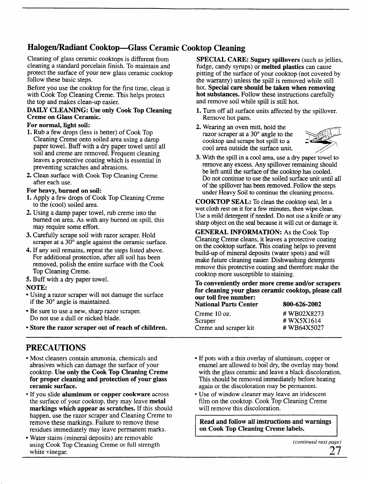
2. Wearing an oven mitt, hold the
razor scraper at a 30° angle to the
9
+,c$,~: .:-.
cooktop and scrape hot spill to a : “- ‘“”
cool area outside the surface unit.
3. With the spill in a cool area use a dry paper towel to
remove any excess. Any spillover remaining should
be lefi until the surface of the cooktop has cooled.
Do not continue to use the soiled surface unit until all
of the spillover has been removed. Follow the steps
under Heavy Soil to continue the cleaning process.
COOKTOP SEAL: To clean the cooktop seal, let a
wet cloth rest on it for a few minutes, then wipe clean.
Use a mild detergent if needed. Do not use a knife or any
sharp object on the seal because it will cut or damage it.
GENERAL INFORMATION: As the Cook Top
Cleaning Creme cleans, it leaves a protective coating
on the cooktop surface. This coating helps to prevent
build-up of mineral deposits (water spots) and will
make future cleaning easier. Dishwashing detergents
remove this protective coating and therefore make the
cooktop more susceptible to staining.
To conveniently order more creme and/or scrapers
for cleaning your glass ceramic cooktop, please call
our toll free number:
National Parts Center 800-626-2002
Creme 10 oz.
# WB02X8273
Scraper
# WX5X1614
Creme and scraper kit
# WB64X5027
. If pots with a thin overlay of aluminum, copper or
enamel are allowed to boil dry, the overlay may bond
with the glass ceramic and leave a black discoloration.
This should be removed immediately before heating
again or the discoloration may be permanent.
s Use of window cleaner may leave an iridescent
film on the cooktop. Cook Top Cleaning Creme
will remove this discoloration.
Read and follow all instructions and warnings
on Cook Top Cleaning Creme labels.
(continued next page)
27
CARE AND CLEANING
(continued)
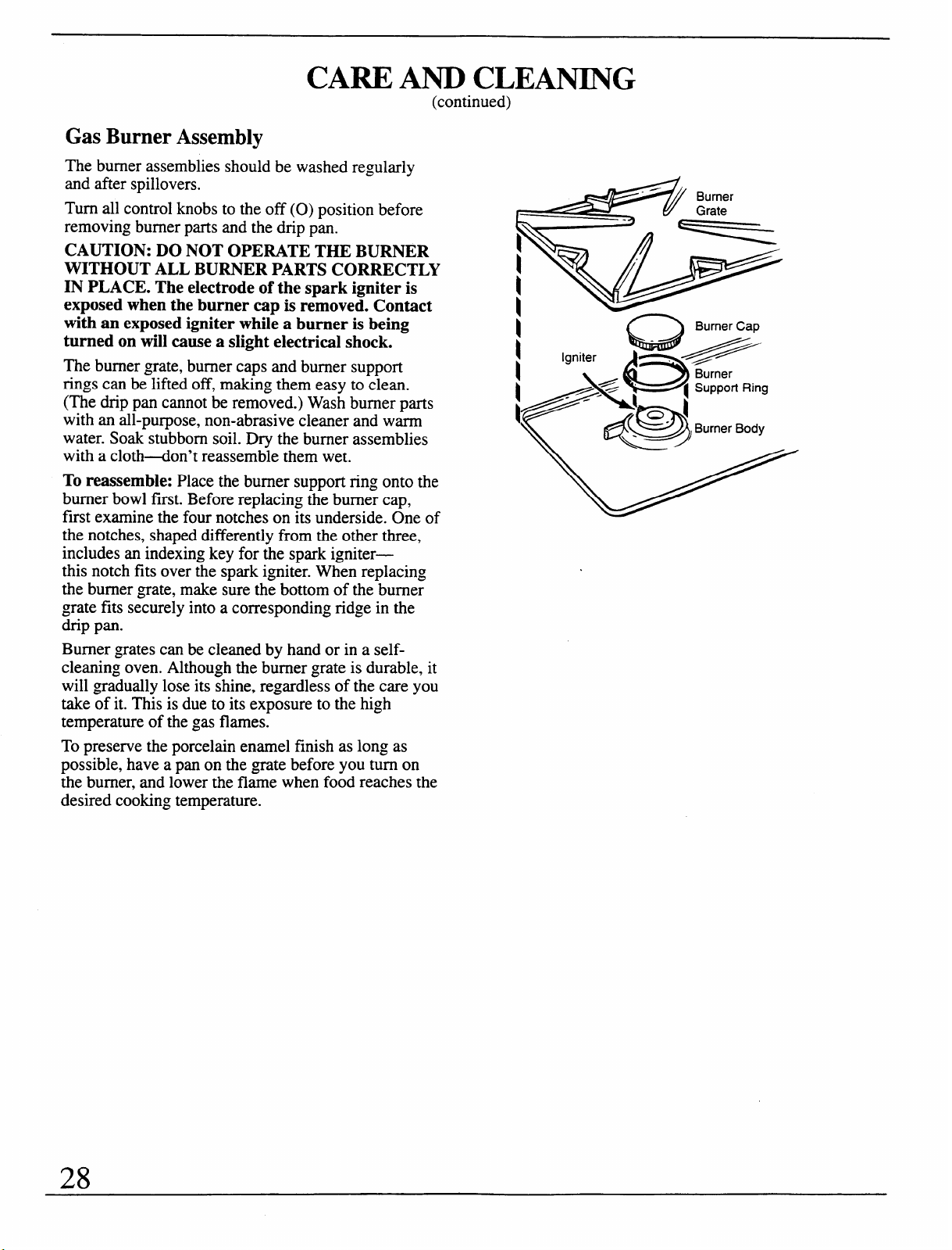
Gas Burner Assembly
The burner assemblies should be washed regularly
and after spillovers.
Turn all control knobs to the off (0) position before
removing burner parts and the drip pan.
CAUTION: DO NOT OPERATE THE BURNER
WITHOUT ALL BURNER PARTS CORRECTLY
IN PLACE. The electrode of the spark igniter is
exposed when the burner cap is removed. Contact
with an exposed igniter while a burner is being
turned on will cause a slight electrical shock.
The burner grate, burner caps and burner support
rings can be Iifted off, making them easy to clean.
(The drip pan cannot be removed.) Wash burner parts
with an all-purpose, non-abrasive cleaner and warm
water. Soak stubborn soil. Dry the burner assemblies
with a cloth-don’t reassemble them wet.
To reassemble: Place the burner support ring onto the
burner bowl first. Before replacing the burner cap,
first examine the four notches on its underside. One of
the notches, shaped differently from the other three,
includes an indexing key for the spark igniter—
this notch fits over the spark igniter. When replacing
the burner grate, make sure the bottom of the burner
orate fits securely into a corresponding ridge in the
arip pan.
Burner grates can be cleaned by hand or in a self-
cleaning oven. Although the burnergrate is durable, it
will ~qaduallylose its shine, regardless of the care you
take of it. This is due to its exposure to the high
temperatureof the gas flames.
To preserve the porcelain enamel finish as long as
possible, have a pan on the grate before you turn on
the burner, and lower the flame when food reaches the
desired cooking temperature.
Burner
~ Support Ring
.
r o-
I
?!!
, Burner Bodv
28
Grill Component
Clean the grill component after every use. Do not put
the element into water. It cleans itself when heated
during normal use. To remove any charred soil, clean
with a dry, stiff brush when the element is cool. Never
use steel wool or metal scouring pads because they
may damage the outer casing of the element.
Wash the grill grate in the sink in soap and water.
The grate may be soaked in a solution of dishwasher
detergent and hot water. Use a non-metal scouring
pad if necessary. Do not use abrasive cleaning
products. The grill grate can also be cleaned in a
self-cleaning oven.
From time to time, you should recondition the
grate with no-stick cooking spray. See the Grill
Component section.
Wash the porcelain enamel drip pan in the sink with
soap and water, or put it in the dishwasher. Soak
stubborn stains, then rub gently with a scouring pad.
Do not put the drip pan in the oven during a self-
cleaning cycle. Doing so will cause discoloration
and damage the finish.
Griddle Accessory
After cooking a greasy food, wipe the non-stick
To prolong the life of the griddle, hold the plug box
oriddle with a dry paper towel while it is still warm.
part of the griddle out of the water when cleaning.
fie careful not to bum your fingers. When the griddle
From time to time, recondition the ~tiddle with no-stick
is cool, wash it in the sink in soap and water. Use a
cooking spray. See the Griddle Accessory section.
non-metal scouring pad if necessary. Do not use
abrasive cleaning products. Do not wash in the
It is a good idea to store the griddle on one edge.
dishwasher or in any way immerse the electrical
If you lay it flat, pans or other cookware maybe put
plug and box.
on top and scratch the non-stick coating.
Porcelain Enamel Grease Well
Porcelain enamel can crack or chip with misuse.
When cleaning a porcelain enamel grease well, be
Itcan stain if spillovers of foods with a high acid careful not to get the electrical receptacles wet. Do
content (such as tomatoes or lemon juice) are not not try to fill the well with water when cleaning. Be
cleaned up quickly. sure the drain hole and tube in the grease well are
not clogged.
Grease Jars
On the underside of the grill cooktop component, a
crease jar is mounted to catch fat and drippings.
a
The lid of the jar is permanently mounted to the
bottom of the cooktop component box. The lid is
connected by a tube to a spout at the front of the
grease well. The jar can be unscrewed from the lid to
be emptied and cleaned or to be replaced. The jar is a
standard 1-pint jar. Quart canning jars may also fit.
Do not use thin-walled glass or plastic jars, such
as those having contained food products. Such jars
could fracture.
Different foods give different amounts of fat and
drippings, so you should inspect the jar each time it is
used. If the jar is not emptied or replaced often enough,
the fat and drippings may overflow. Be sure the drain
hole and tube in the grease well are not clogged.
(continued next page)
29
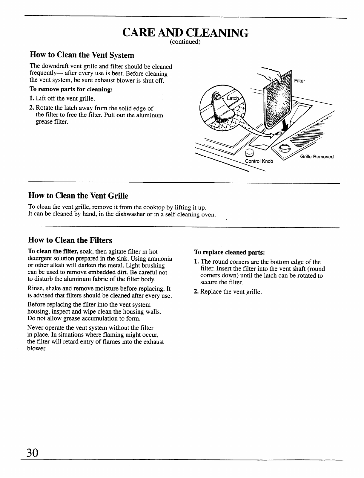
CARE AND CLEANING
(continued)
How to Clean the Vent System
The downdraft vent grille and filter should be cleaned
frequently—
after every use is best. Before cleaning
the vent system, be sure exhaust blower is shut off.
To remove parts for cleaning:
1. Lift off the vent ~tille.
2. Rotate the latch away from the solid edge of
the filter to free the filter. Pull out the aluminum
grease filter.
How to Clean the Vent Grille
To clean the vent ~tille, remove it from the cooktop by lifting it up.
It can be cleaned by hand, in the dishwasher or in a self-cleaning oven.
How to Clean the Filters
To clean the falter, soak, then agitate filter in hot
To replace cleaned parts:
detergent solution prepared in the sink. Using ammonia
1. The round comers are the bottom edge of the
or other alkali will darken the metal. Light brushing
filter. Insert the filter into the vent shaft (round
can be used to remove embedded dirt. Be careful not
to disturb the aluminum fabric of the filter body.
comers down) until the latch can be rotated to
secure the filter.
Rinse, shake and remove moisture before replacing. It
2. Replace the vent grille.
is advised that filters should be cleaned afier every use.
Before replacing the filter into the vent system
housing, inspect and wipe clean the housing walls.
Do not allow grease accumulation to form.
Never operate the vent system without the filter
in place. In situations where flaming might occur,
the filter will retard entry of flames into the exhaust
blower.
30
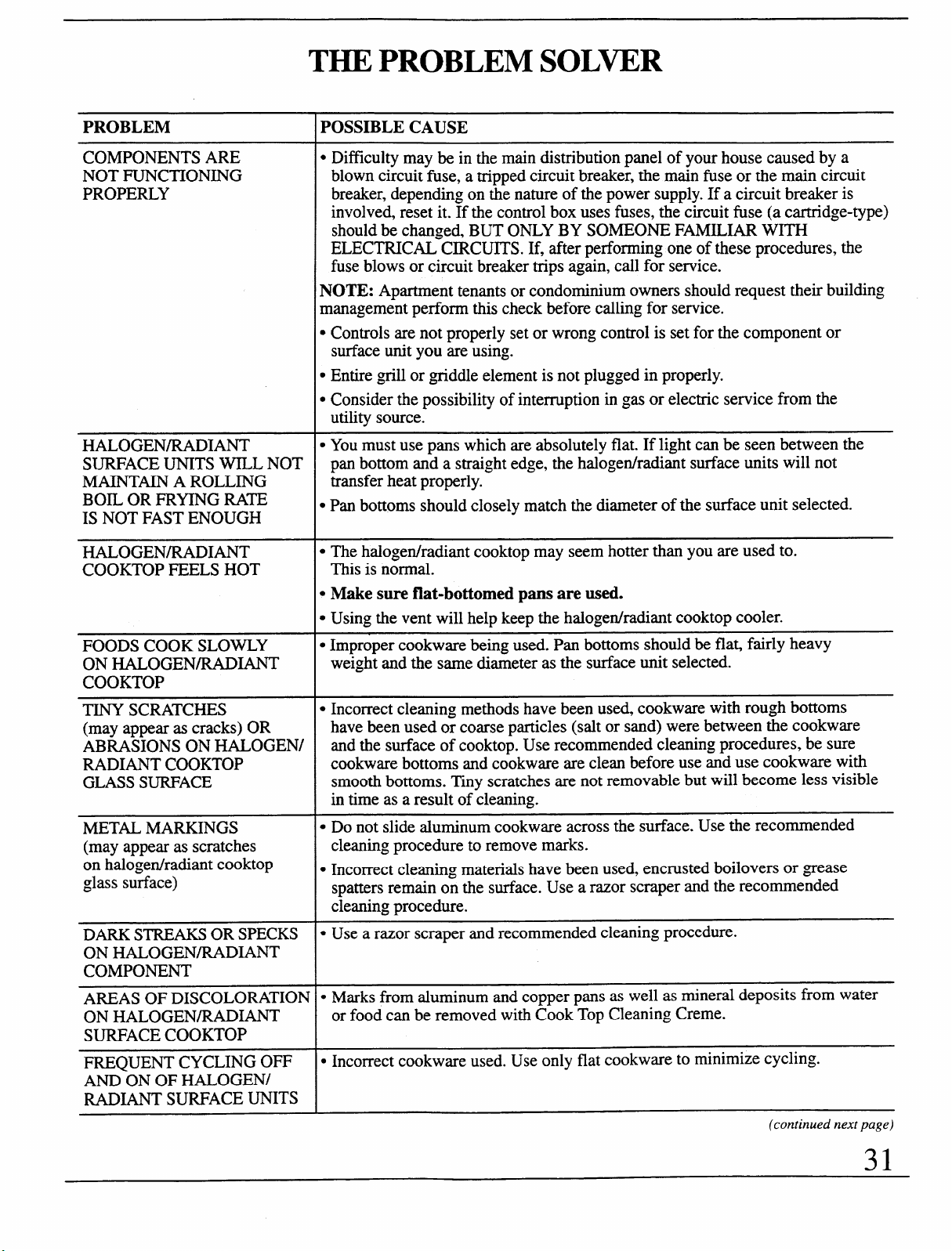
THE PROBLEM SOL~R
PROBLEM
COMPONENTS ARE
NOT FUNCTIONING
PROPERLY
HALOGENRADIANT
SURFACE UNITS WILL NOT
MAINTAIN A ROLLING
BOIL OR FRYING RATE
IS NOT FAST ENOUGH
HALOGEN/RADIANT
COOKTOP FEELS HOT
FOODS COOK SLOWLY
ON HALOGENRA.DIANT
COOKTOP
TINY SCRATCHES
(may appear as cracks) OR
ABRASIONS ON HALOGEN1
RADIANT COOKTOP
GLASS SURFACE
METAL MARKINGS
(may appear as scratches
on halogenhadiant cooktop
glass surface)
DARK STREAKS OR SPECKS
ON HALOGE.NRADIANT
COMPONENT
AREAS OF DISCOLORATION
ON HALOGEN/RADIANT
SURFACE COOKTOP
FREQUENT CYCLING OFF
AND ON OF HALOGENJ
RADIANT SURFACE UNITS
POSSIBLE CAUSE
● Difficulty may be in the main distribution panel of your house caused by a
blown circuit fuse, a tripped circuit breaker, the main fise or the main circuit
breaker, depending on the nature of the power supply. If a circuit breaker is
involved, reset it. If the control box uses fuses, the circuit fuse (a cartridge-type)
should be changed, BUT ONLY BY SOMEONE FAMILIAR WITH
ELECTRICAL CIRCUITS. If, after performing one of these procedures, the
fuse blows or circuit breaker trips again, call for semice.
NOTE: Apartment tenants or condominium owners should request their building
management perform this check before calling for service.
● Controls are not properly set or wrong control is set for the component or
surface unit you are using.
c Entire grill or griddle element is not plugged in properly.
c Consider the possibility of interruption in gas or electric service from the
utility source.
c You must use pans which are absolutely flat. If light can be seen between the
pan bottom and a straight edge, the halogenhadiant surface units will not
transfer heat properly.
● Pan bottoms should closely match the diameter of the surface unit selected.
● The halogen/radiant cooktop may seem hotter than you are used to.
This is normal.
c Make sure flat-bottomed pans are used.
● Using the vent will help keep the halogenhadiant cooktop cooler.
● Improper cookware being used. Pan bottoms should be fla~ fairly heavy
weight and the same diameter as the surface unit selected.
● Incorrect cleaning methods have been used, cookware with rough bottoms
have been used or coarse particles (salt or sand) were between the cookware
and the surface of cooktop. Use recommended cleaning procedures, be sure
cookware bottoms and cookware are clean before use and use cookware with
smooth bottoms. Thy scratches are not removable but will become less visible
in time as a result of cleaning.
● Do not slide aluminum cookware across the surface. Use the recommended
cleaning procedure to remove marks.
c Incorrect cleaning materials have been used, encrusted boilovers or ~~ease
spatters remain on the surface. Use a razor scraper and the recommended
cleaning procedure.
● Use a razor scraper and recommended cleaning procedure.
● Marks from aluminum and copper pans as well as mineral deposits from water
or food can be removed with Cook Top Cleaning Creme.
c Incorrect cookware used. Use only flat cookware to minimize cycling.
(continued next page)
31
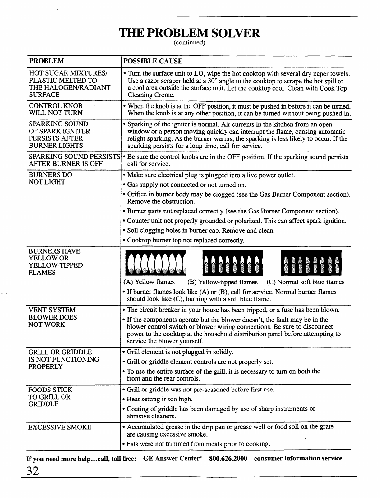
THE PROBLEM SOLWR
PROBLEM
HOT SUGAR MIXTURES/
PLASTIC MELTED TO
THE HALOGEN/RADIANT
SURFACE
CONTROL KNOB
WILL NOT TURN
SPARKING SOUND
OF SPARK IGNITER
PERSISTS AFTER
BURNER LIGHTS
SP~KING SOUND PERSIST$
AIWER BURNER IS OFF
BURNERS DO
NOT LIGHT
BURNERS HAVE
YELLOW OR
YELLOW-TIPPED
FLAMES
VENT SYSTEM
BLOWER DOES
NOT WORK
GRILL OR GRIDDLE
IS NOT FUNCTIONING
PROPERLY
FOODS STICK
TO GRILL OR
GRIDDLE
EXCESSIVE SMOKE
(continued)
POSSIBLE CAUSE
● Turn the surface unit to LO, wipe the hot cooktop with several dry paper towels.
Use a razor scraper held at a 30° angle to the cooktop to scrape the hot spill to
a cool area outside the surface unit. Let the cooktop COO1.Clean with Cook Top
Cleaning Creme.
● When the knob is at the OFF position, it must be pushed in before it can be turned.
When the knob is at any other position, it can be turned without being pushed in.
s Sparking of the igniter is normal. Air currents in the kitchen from an open
window or a person moving quickly can interrupt the flame, causing automatic
relight sparking. As the burner warms, the sparking is less likely to occur. If the
sparking persists for a long time, call for service.
● Be sure the control knobs are in the OFF position. If the sparking sound persists
call for service.
. Make sure electrical plug is plugged into a live power outlet.
. Gas supply not connected or not turned on.
● Orifice in burner body may be clogged (see the Gas Burner Component section).
Remove the obstruction.
● Burner parts not replaced correctly (see the Gas Burner Component section).
. Counter unit not properly ~groundedor polarized. This can affect spark ignition.
● Soil clogging holes in burner cap. Remove and clean.
● Cooktop burner top not replaced correctly.
(A) Yellow flames
(B) Yellow-tipped flames (C) Normal soft blue flames
● If burnerflames look like (A) or (B), call for service. Normal burnerflames
should look like (C), burning with a soft blue flame.
● The circuit breaker in your house has been tripped, or a fuse has been blown.
● If the components operate but the blower doesn’t, the fault may be in the
blower control switch or blower wiring connections. Be sure to disconnect
power to the cooktop at the household distribution panel before attempting to
service the blower yourself.
● Grill element is not plugged in solidly.
* GriIl or ~tiddle element controls are not properly set.
● To use the entire surface of the ~till, it is necessary to turn on both the
front and the rear controls.
. Grill or ~tiddle was not pre-seasoned before first use.
● Heat setting is too high.
. Coating of griddle has been darnaged by use of sharp instruments or
abrasive cleaners.
s Accumulated ~~easein the drip pan or ~~easewell or food soil on the grate
are causing excessive smoke.
. Fats were not trimmed from meats prior to cooking.
If you need more help... call, toll free:
GE Answer Center@ 800.626.2000 consumer information service
32
.
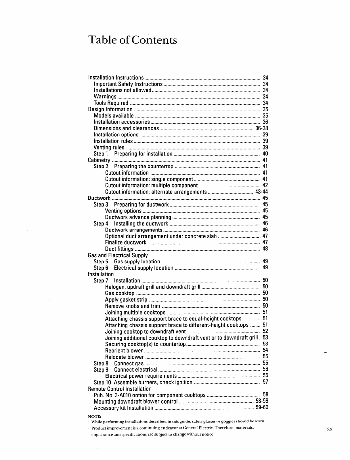
Table of Contents
Installation Instructions
.......................................................................................... 34
Important Safety Instructions ........................................................................... 34
Installations not allowed .................................................................................... 34
Warnings ............................................................................................................... 34
Tools Required ..................................................................................................... 34
Design Information .................................................................................................. 35
Models available
.................................................................................................
35
Installation accessories ..................................................................................... 36
Dimensions and clearances
........................................................................
36-38
Installation options ............................................................................................. 39
Installation rules .................................................................................................. 39
Venting rules ........................................................................................................ 39
Step 1 Preparing for installation ................................................................... 40
Cabinetry
...................................................................................................................
41
Step 2 Preparing the countertop
..................................................................
41
Cutout information ..................................................................................... 41
Cutout information: single component ................................................... 41
Cutout information: multiple component ............................................... 42
Cutout information: alternate arrangements ...................................
43-44
Ductwork ...................................................................................................................
45
Step 3 Preparing for ductwork ...................................................................... 45
Venting options ........................................................................................... 45
Ductwork
advance planning
....................................................................
45
Step 4 Installing the ductwork
......................................................................
46
Ductwork arrangements ...........................................................................
46
Optional duct arrangement under concrete slab ................................. 47
Finalize ductwork
.......................................................................................
47
Duct fittings ................................................................................................. 48
Gas and Electrical Supply
Step 5 Gas supply location ............................................................................ 49
Step 6 Electrical supply location
..................................................................
49
Installation
Step 7 Installation ............................................................................................ 50
Halogen, updraft grill and downdraft grill
.............................................
50
Gascooktop................................................................................................ 50
Apply gasket strip ......................................................................................
50
Remove knobs and trim ............................................................................ 50
Joining multiple cooktops ........................................................................ 51
Attaching chassis support brace to equal-height cooktops ..............51
Attaching chassis support brace to different-height cooktops ........51
Joining cooktop to downdraft vent ......................................................... 52
Joining additional cooktop to downdraft vent or to downdraft grill. 53
Securing cooktop(s) to countefiop ......................................................... 53
Reorient blower .......................................................................................... 54
Relocate blower
.........................................................................................
55
Step 8 Connect gas ........................................................................................- 55
Step 9 Connect electrical
...............................................................................
56
Electrical power requirements ................................................................ 56
Step 10 Assemble burners, check ignition
...................................................
57
Remote Control Installation
Pub. No. 3-AO1O option for component cooktops ......................................... 58
Mounting downdraft blower control
..........................................................
58-59
Accessory kit Installation ............................................................................. 59-60
NC)TE:
While performing installations described in this guide. safety glasses or goggles should be worn.
Product improvement is a continuing endeavor at General Electric. Therefore, materials.
appearance and specifications are subject to change without notice.
33
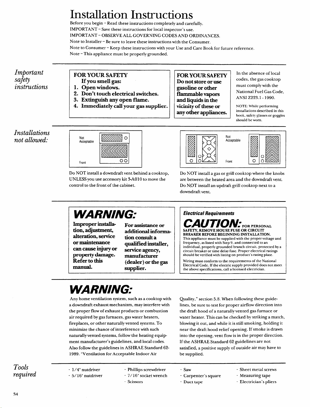
Installation Instructions
Important
safety
instructions
Installations
not allowed:
Took
required
Before you begin – Read these instructions completely and carefully.
IMPORTANT – Save these instructions for local inspector’s use.
IMPORTANT - OBSERVE ALL GOVERNING CODES AND ORDINANCES.
A1ote to Installer -Be sure to leave these instructions with the Consumer.
Note to Consumer - Keep these instructions with your Use and Care Book for future reference.
Note - This appliance must be properly grounded.
FOR YOUR SAFETY
If you smell gas:
1. Open windows.
2. Don’t touch electrical switches.
3. Extinguish any open flame.
4. Immediately call your gas supplier.
FOR YOUR SAFETY
Do not store or use
gasoline or other
flammable vapors
and liquids in the
vich+ of these or
any other appliances.
In the absence of local
codes, the gas cooktop
must comply with the
National Fuel Gas Code.
ANSI Z223.1 -1990.
NOTE: While performing
installations described in this
book. safety glasses or goggles
should be worn.
Not
El
o
Acceptable
Front
00
Do NOT install a downdraft vent behind a cooktop,
UNLESS you use accessory kit .3-AOI Oto move the
control to the front of the cabinet.
Do NOT install a gas or grill cooktop where the knobs
are between the heated area and the downdraft vent.
Do N,OT install an updraft grill cooktop next to a
downdraft vent.zyxwvutsrqponmlkjihgfedcbaZYXWVUTSRQPONMLKJIHGFEDCBA
WARNING:
Improper install-
ation,adjustmen$
alte=tion, service
or maintenance
can cause injury or
property damage.
Refer to this
manual.
For assistance or
additional informa-
tion consult a
qualified installer,
service agenq,
manufacturer
(dealer) or the gas
supplier.
Electrical Requirements
CAUTION:,.,~..s....
SAFETY, REMOVEHOUSEFUSEORCIRCUIT
BREAKERBEFOREBEGINNINGINSTALLATION.
This appliance must be supplied with the proper voltage and
frequency, as listed with Step 9, and connected to an
individual, properly grounded branch circuit, protected by a
circuit breaker or time delay fuse. Proper electrical ratings
should be verified with listing on product’s rating plate.
Wiring must conform to the requirements of the National
Electrical Code. If the electric supply provided does not meet
the above specifications, call a licensed electrician.
WARNING:
Any home ventilation system, such as a cooktop with
a downdraft exhaust mechanism, may interfere with
the proper flow of exhaust products or combustion
air required by gas furnaces, gas water heaters,
fireplaces, or other naturally vented systems. To
minimize the chance of interference with such
naturally vented systems, follow the heating equip
ment manufacturer’s guidelines, and local codes.
Also follow the guidelines in ASHRAE Standard 62-
1989. “Ventilation for Acceptable Indoor Air
Quality,” section 5.8. When following these guide-
lines, be sure to test for proper airflow direction into
the draft hood of a naturally vented gas furnace or
water heater. This can be checked by striking a match,
blowing it out, and while it is still smoking, holding it
near the draft hood relief opening. If smoke is drawn
into the opening, vent flow is in the proper direction.
If the ASHILAE Standard 62 guidelines are not
satisfied, a positive supply of outside air may have to
be supplied.
“ 1/4” nutdriver
“ Phillips screwdriver “ Saw
“ Sheet metal screws
“ 5/16” nutdriver
“ 7/ 16“ socket wrench
“ Carpenter’s square
“ Measuring tape
“ Scissors “ Duct tape
“ Electrician’s pliers
34
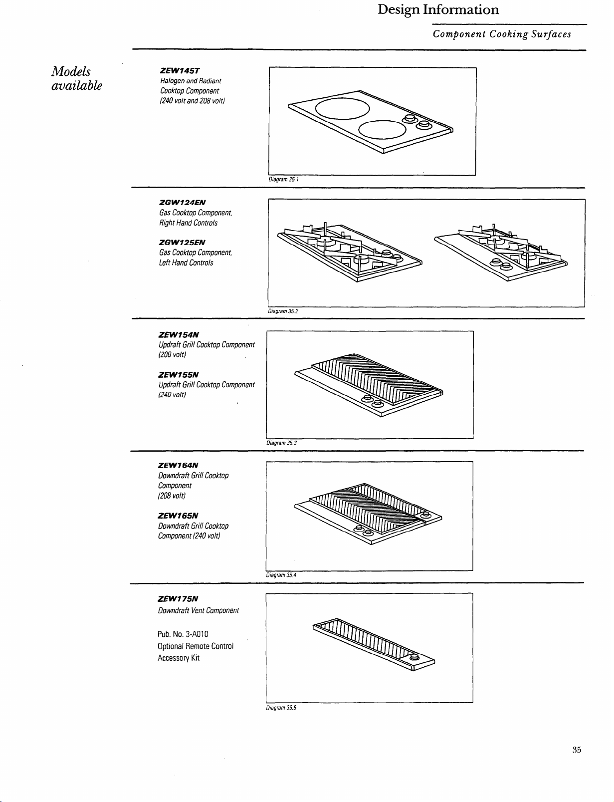
Design Information
Mode&
available
Component Cooking SurfaceszyxwvutsrqponmlkjihgfedcbaZYXWVUTSRQPONMLKJIHGFEDCBA
ZEW745T
Halogen and Radian?
Cooktop Component
(240 volt and208 volt)
Diagram 35.t
ZGW724EN
Gas Cooktop Component.
Right Hand Controls
ZG W125EN
Gas Cooktop Component,
Left Hand Controls
,.” . . . ZJr ‘7
ZEW154N
Updrafi Grill Cooktop Component
(208 voh)
ZEW155N
Updraft Grill Cooktop Component
(240 volt)
I
Diagram 35.3
ZEW164N
Downdraft Grill Cooktop
Component
(208 volt)
ZEW165N
Downdraft Grill Cooktop
Component (240 volt)
. .,..
uiagram XI 4
ZEW175N
Downdraft Vent Component
Pub.
No. 3-AO1O
Optional Flemote Control
Accessory Kit
I
I
Diagram 35.5
35
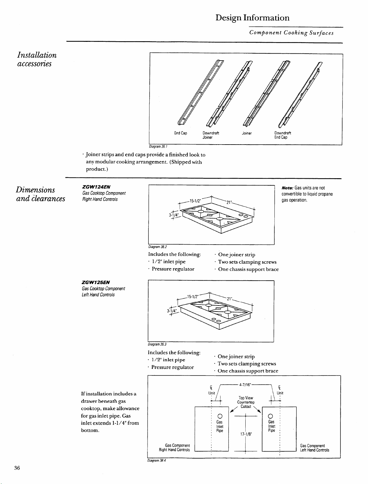
Design Information
Component Cooking Surfaces
Installation
accesson”es
End Cap Downdraft
.lomer
Downdraft
Joiner
End Cap
“ Joiner strips and end caps provide a finished look to
any modular cooking arrangement. (Shipped with
product.)
Dimensions
----zyxwvutsrqponmlkjihgfedcbaZYXWVUTSRQPONMLKJIHGFEDCBA
ZG W124EN
Gas Cooktoo Comoonent
and clearances
Right Hand Controls
ZG W725EN
Gas Cooktop Component
Left Hand Controls
If installation includes a
drawer beneath gas
cooktop, make allowance
for gas inlet pipe. Gas
inlet extends 1-1/4” from
bottom.
~ote; Gas units are not
convertible to liquid propane
gas operation.
“T*>
I
I
Dtagram 36.3
Includes the following:
- One joiner strip
. 1/2” inlet pipe
- Two sets clamping screws
. Pressure regulator
“ One chassis support brace
1
D/agram 36.3
Includes the following:
. 1/2” inlet pipe
. One joiner strip
. Pressure regulator
. Two sets clamping screws
. One chassis support brace
Gas Component
Right Hand Controls
Gas Component
Left Hand Controls
Dtagram364
36
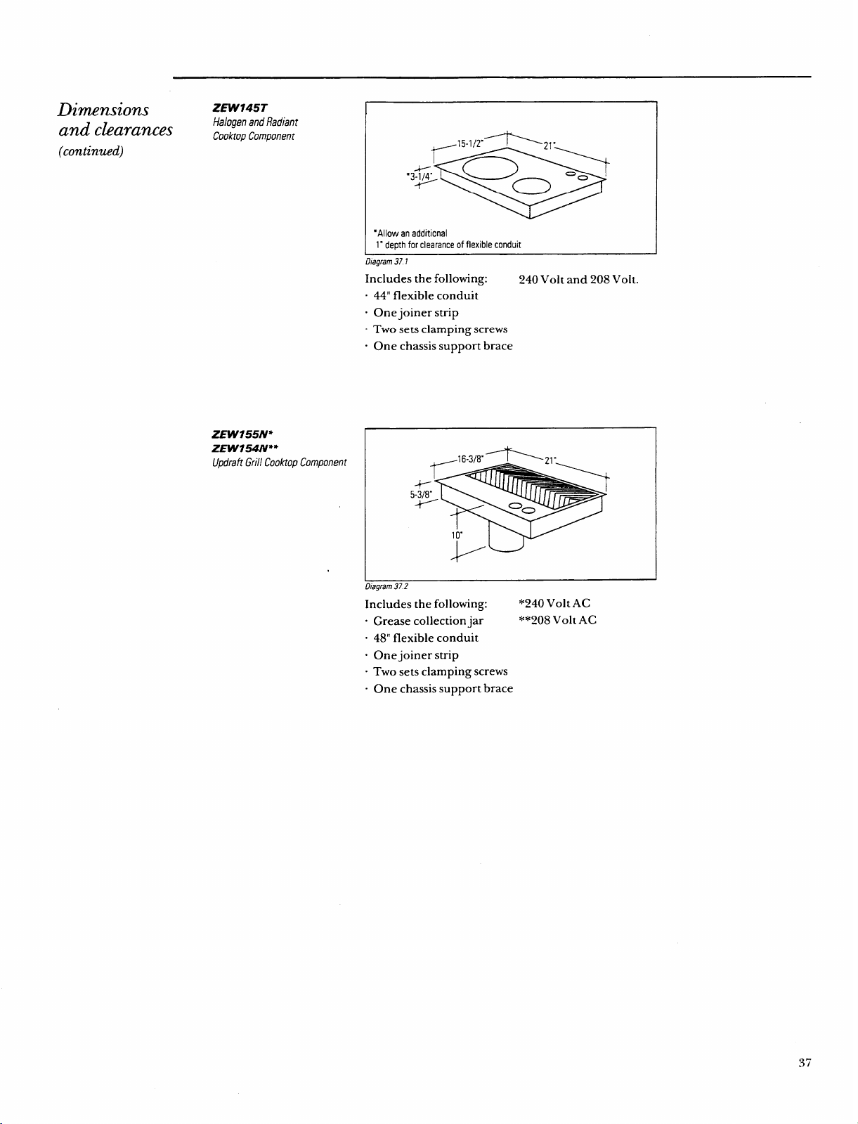
Dimensions
and clearances
(continued)zyxwvutsrqponmlkjihgfedcbaZYXWVUTSRQPONMLKJIHGFEDCBA
ZEW145T
Halogen and Radiant
Cooktop Component
I
I
-+-”
●zyxwvutsrqponmlkjihgfedcbaZYXWVUTSRQPONMLKJIHGFEDCBA3P
I
●Allow an additional
1- depth for clearance of flexible conduit
D/agram371
Includes the following:
240 Volt and 208 Volt.
44” flexible conduit
One joiner strip
Two sets clamping screws
One chassis support brace
ZEW155N*
ZEW154N**
Updrafi Grill Cooktop Component
5%”
1
o“
k
I
Diagram 372
Includes the following:
*240 Volt AC
“ Grease collection jar
X*~08VoltAC
“ 48” flexible conduit
“ One joiner strip
“ Two sets clamping screws
“ One chassis support brace
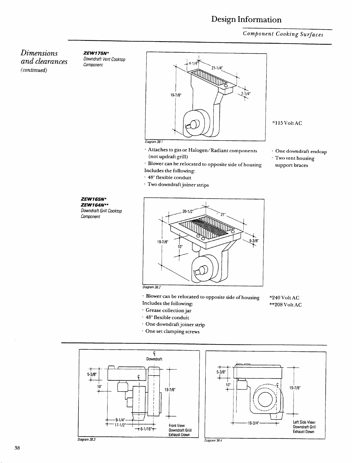
Design Information
Component Cooking Surfaces
Dimensions
and clearances
(continued)zyxwvutsrqponmlkjihgfedcbaZYXWVUTSRQPONMLKJIHGFEDCBA
ZEWI 75N*
Downdraft Vent Cooktop
Component
I
19-7/8”
I h-l
IJagram 381
. Attaches to gas or Halogen/Radiant components
(not updraft grill)
- Blower can be relocated to opposite side of housing
Includes the following:
. 48” flexible conduit
“ Two downdraftjoiner strips
ZEW165N*
ZEW164M**
Downdraft Grill Cooktop
Component
. Blower can be relocated to opposite side of housing
Includes the following:
. Grease collection jar
. 48” flexible conduit
“ One downdraft joiner strip
. One set clamping screws
*115Volt AC
One downdraft endcap
Two vent housing
support braces
*240 Volt AC
**208 Volt AC
i
Downdrafl
‘17-1/2’
I
I
1
46-1/16.+
T
19-7/0”
Front View
Downdraft Grill
Exhaust Down
sgram 38.3
-
d
)
+1-3
5-3/8”
,.-
L -:::~:::~’
0
(’” ‘j
\
,)I
‘.
‘..
.“J
..----
1
+16-3K------+
19-7/8.
+-
Left Side View
Downdraft Grill
Exhaust Down
uiagramJ84
Installation
o@ons
Installation
rules
Venting
ruzes
The Monogram Component Cooktop System offers the
ultimate in design and cooking flexibility, with modular
cooktops and accessories, providing a variety of cooking
technologies to meet the needs of the most discerning
cook.
“ Each component can be installed in many orientations
in the countertop.
“ Both gas and electric components can be combined
within the cooking configurations:
– Multiple electric components can operate from a
single junction box, if local codes permit.
– Multiple gas components can operate from a
manifold, as permitted by local codes.
- Updraft components can be vented according to
normal exhausting methods.
“ The downdraft grill or vent blower maybe oriented in
two directions—toward the rear or down as required.
Blower can be mounted to left or right side of vent
housing.
. Gas and halogen components are only 3-1 /4” deep,
allowing room for a drawer beneath in many cabinet
styles.
. Optional Remote Control Accessory Kit for downdraft
vent component is available for use when remote
control of blower is desired.
. Always choose cabinetry that enhances installation
“ Always consider option to shorten drawer for gas inlet
process.
clearance. (To determine location of gas pipe, refer to
. Always anticipate that cabinet modification maybe
cutout illustration in “Design Information, Dimensions
required for European or other custom cabinetry.
and clearances. )
“ Always preplan electrical and gas connections to be
. Gas components cannot be converted to liquid
accessible at installation time.
. Always consider distance to power supply, cable
propane gas operation.
lengths and bending restrictions before cutting holes.
. Always preplan component locations before installa-
. If possible, don’t cut holes for remote mount vent
tion; determine need to reorient downdraft blower
control and ductwork locations until components are
discharge direction, or if blower will need to be
on-site, with countertop in place, and all preplanning
relocated to opposite side of vent housing. (Down-
locations are confirmed.
draft unit is shipped with blower mounted on left side
. Every downdraft vent and downdraft grill cooktop
of housing. )
must have a complete, separate duct run. Ducts from
“ Always consider how cooktop (and grease collection
different downdraft units cannot be combined.
jars) or downdraft vent housing affect cabinet type
. Do NOT install a downdraft vent behind a cooktop,
selection (especially drawers).
UNLESS you use accessory kit 3-AO1 O to move the
. Always provide clearance for remote mount vent
control to the front of the cabinet.
control wiring box when installing on cabinet face
. Do NOT install a gas or grill cooktop where the knobs
between components, or other locations.
are between the heated area and the downdraft vent.
. Always anticipate base cabinet storage arrangements to .
Do NOT install an updraft grill cooktop next to a
accommodate downdraft blower and duct locations.
downdraft vent.
. Never vent a cooktop into an interior space–always
to outdoors.
. Do not install an updraft grill unless overhead vent
is 300 CFM or more.
39
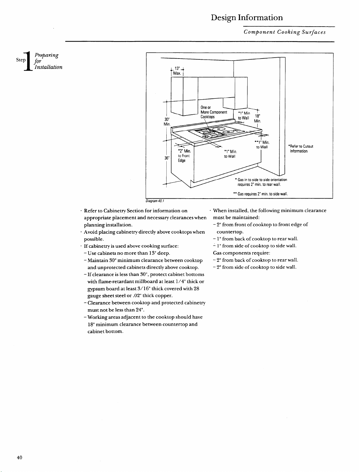
Design Information
Step
Preparing
for
Installation
.
Component Cooking Surfaces
13”
t~
Max.
I II
d
One orzyxwvutsrqponmlkjihgfedcbaZYXWVUTSRQPONMLKJIHGFEDCBA
30”
Min.
A ~
●*1” Min.
●2” Min.
to Wall
●1” Min
36”
to Front
to Wall
Edge
● Gas in to side to side orientation
A
requres 2“ min. to rear wall,
●* Gas requires 2“ min. to side wall
●Refer to Cutout
Information
.---—.“ .
c Refer to Cabinet~ Section for information on
appropriate placement and necessary clearances when
planning installation.
“ Avoid placing cabinetry directly above cooktops when
possible.
- If cabinetry is used above cooking surface:
– Use cabinets no more than 13“ deep.
– Maintain 30” minimum clearance between cooktop
and unprotected cabinets directly above cooktop.
– If clearance is less than 30”, protect cabinet bottoms
with flame-retardant millboard at least 1/4” thick or
~~psum board at least 3/ 16“ thick covered with 28
gauge sheet steel or .02” thick copper.
- Clearance between cooktop and protected cabinetry
must not be less than 24”.
– Working areas adjacent to the cooktop should have
18“ minimum clearance between countertop and
cabinet bottom.
. When installed, the following minimum clearance
must be maintained:
- 2“ from front of cooktop to front edge of
countertop.
– 1” from back of cooktop to rear wall.
-1” from side of cooktop to side wall.
Gas components require:
– 2“ from back of cooktop to rear wall.
– 2“ from side of cooktop to side wall.
40
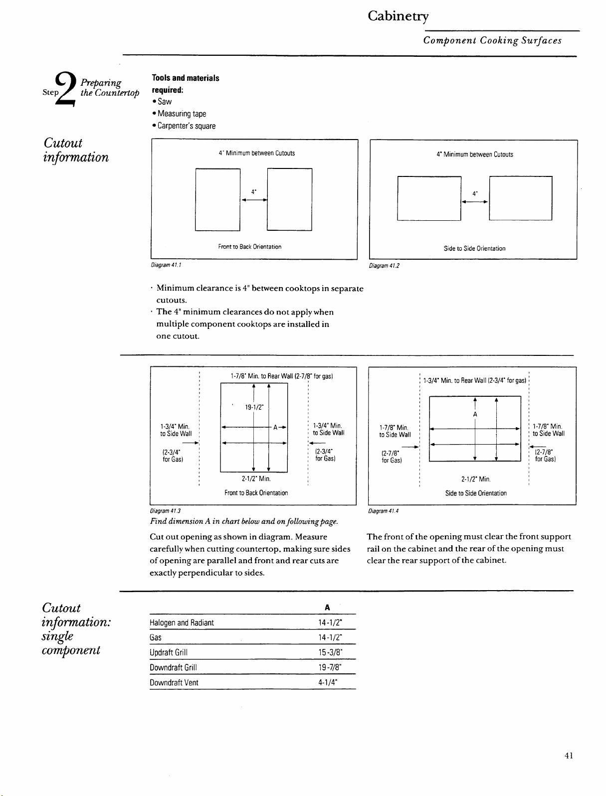
2
Step
cutout
information
cutout
information:
singh
component
Cabinetry
Component Cooking Surfaces
Preparing
Tools and materials
the Counter-t@
required:
● Saw
● Measuring tape
● Carpenter’s square
4“ Mmlmum between Cutouts
Da
4“
Front to Back Orientation
.
Uiagram47. 7
4“ Minimum between Cutouts
n’r
Side to Side Orientation
Llagram41 2
“ Minimum clearance is 4“ between cooktops in separate
cutouts.
“ The 4“ minimum clearances do not apply when
multiple component cooktops are installed in
one cutout.
1-7/8” Min. to Rear Wail (2-7/8” for gas)
1-3/4’ Min. I
to Side Wall :
~;
(2-3/4” ;
for Gas) ,
2-1/2” Mm.
Front to Back Onentatlon
: l-3/~ Min.
I to Side Wall
;4———
: (2-3/4”
: for Gas)
thagrarn 4 T3
Find dimension A in chart below and onfobwingfiage.
Cut out opening as shown in diagram. Measure
carefully when cutting countertop, making sure sides
of opening are parallel and front and rear cuts are
exactly perpendicular to sides.
: 1-3/4” Min. to Rear Wall (2-3/LT for gasl [
t
,
,
,
I
2-1/2” Min
Side to Side Orientation
Diagram 414
The front of the opening must clear the front support
rail on the cabinet and the rear of the opening must
clear the rear support of the cabinet.
A
Halogen and Radiant
14-1/2”
Gas
14-1/29
Updraft Grill
15 -3/8”
Downdraft Grill 19-78”
Downdraft Vent
4-1 /4”
41
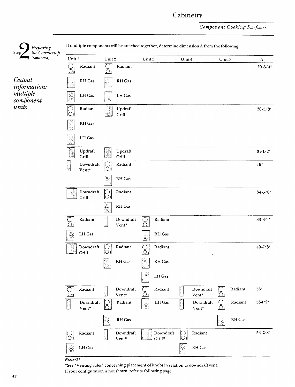
Cabinetry
Component Cooking Surfaces
2
Step
Prepating
If multiple components will be attached together, determine dimension A from the following:
the Count&op
(continued)
Unit 1 Unit 2 Lnit 3
Unit 4
Unit5
A
cutout
information:
multiple
component
units
1
0 Radiant
u
Radiant
o 0
29 -3/4”
El
‘,
El
RH Gas ;:!
RH Gas
. .
.
..:
‘:\ . .
El
Radiant
D
~‘ Updraft
o
30-5/8”
-;
././.. .
Grill
El
....
,.,,
>.
RH Gas
-----
:
~.
D
Downdraft
n
Radiant
~g,l
Vent*
o
H
...
::.
RH Gas
../”
: :1<,
D
I
““”:“;;’ Downdraft O
Radiant
2:
2!} Grill
o
34-5/8”
U
\.
\..\
/+)
RH Gas
. :.+
—
PI
u
Radiant - Downdraft
I
O Radiant
o
0
33-3/4”
.
Vent*
c1
...
c1
...
‘Y q
LH Gas
::
RH Gas
W
. .
.. .
::
.—
—-.
El
.......
:,
,;i
n
Downdraft O
Radiant
D
‘ Radiant
49 -7/8”
: ::,,
:=–c Grill
o 0
SI
-k—.
.
c1
RH Gas ;{’1 RH Gas
,.. ,
,<.
..,:
.:; -
.LL\
El
::
,..
LH Gas
,&
El
SI
O Radiant ~” Downdraft
U
D
Radiant : Downdraft
u
O Radiant 53”
0
..
Vent*
o
Vent*
o
D
L1
Downdraft O
c1
Radiant ~,~
SI
LH Gas “’”
Downdraft
n
O Radiant
53-1/2”
Vent*
o
., ,..
..
Vent*
o
n
II
O Radiant ““
❑
Downdraft “,”~ Downdraft
n
Radiant
53-7/8”
o
.,.
c
Vent* :-‘
l“.’ Gri]l*
o
H
~{~ LHGas
n
\_—.
...*
/o~
~$
RH Gas
_{
.-. .,
L3agrarn42.1
*See “Venting rules” concerning placement of knobs in relation to downdraft vent.
If your configuration is not shown, refer to following page.
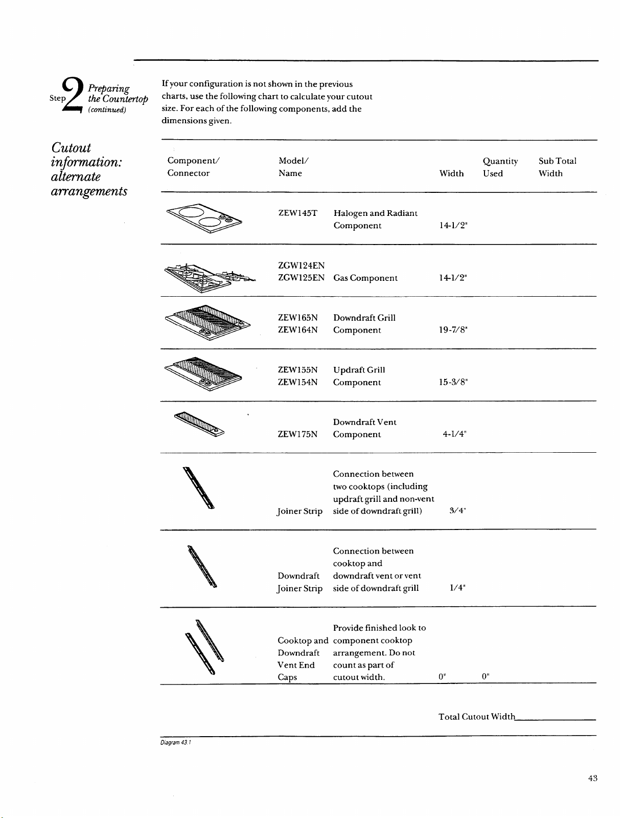
2
Preparing
If your configuration is not shown in the previous
Step
the Counter-top
charts, use the following chart to calculate your cutout
(continued)
size. For each of the following components, add the
dimensions given.
cutout
information:
altmate
arrangements
Component/ Model/ Quantity Sub Total
Connector
Name Width
Used
Width
-
ZEW145T
Halogen and Radiant
Component
141/2”
ZGW124EN
ZGW125EN Gas Component
141/2”
ZEW165N
Downdraft Grill
ZEW164N
Component
19-7/8”
ZEW155N
Updraft Grill
ZEW154N
Component
15-3/8”
4-1/4”
\
Connection between
two cooktops (including
updraft grill and non-vent
Joiner Strip side of downdraft grill)
3/4”
\
Connection between
cooktop and
Downdraft
downdraft vent or vent
Joiner Strip side of downdraft grill
1/4”
Provide finished look to
+
Cooktop and component cooktop
Downdraft arrangement. Do not
Vent End
count as part of
Caps cutout width.
()!!
o“
Total Cutout Width
Llagram 43 I
43
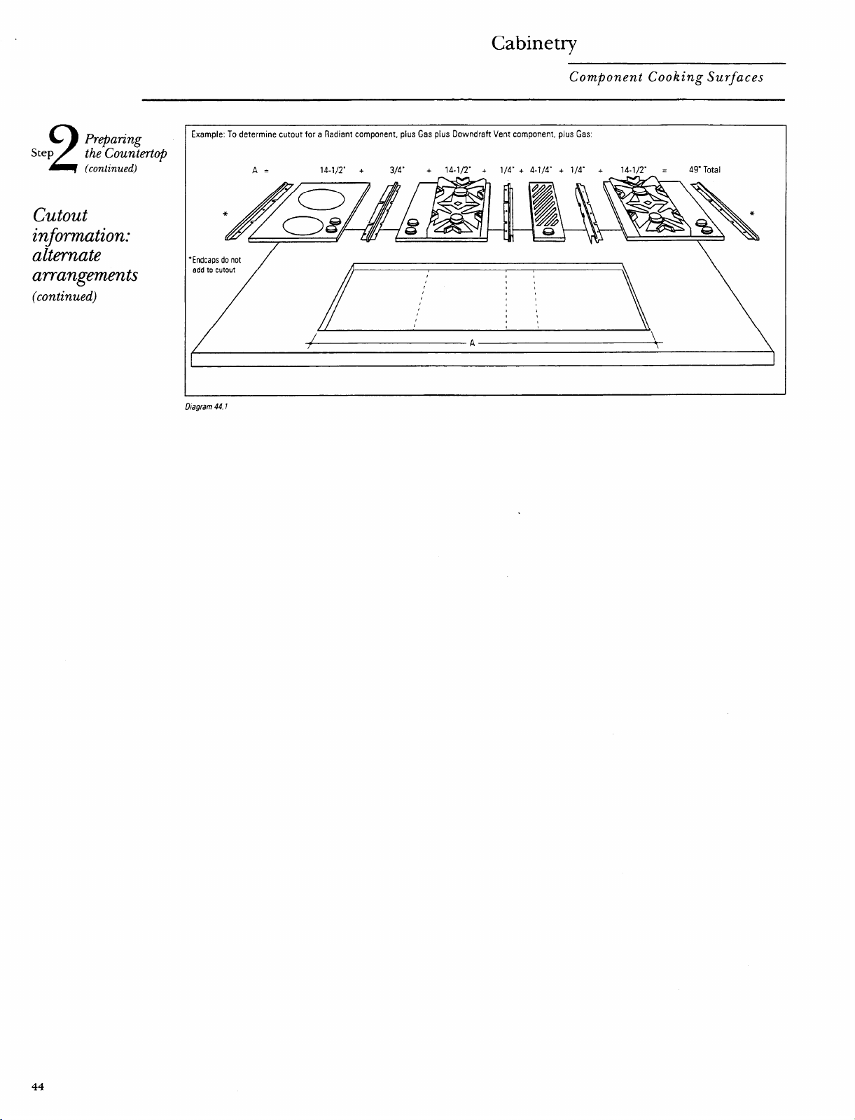
Cabinetry
Component Cooking Surfaces
2
Step
Prepating
the Countertc@
(continued)
cutout
information:
alternate
arrangements
(continued)
Example. To determine cutout for a Radiant component, plus Gas plus Downdraft Vent component, plus Gas
A= 14-1/2” + 3/4” + 14-1/2” +
1/4” + 4-1/4” + 1/4” +
14-1/2” =
49” Total
‘Endcapsdo not
add to cutout
~A~
44
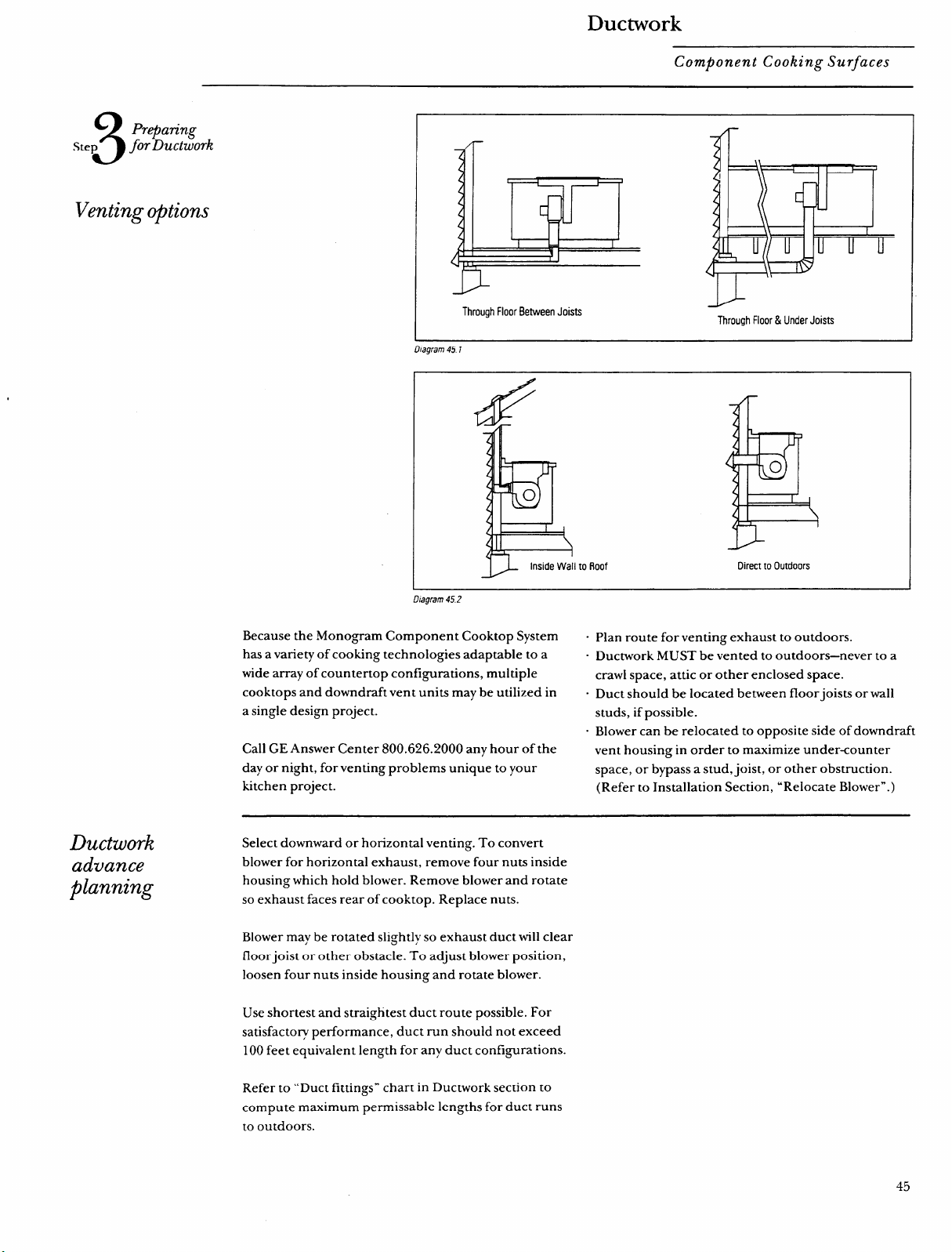
Ductwork
Component Cooking Surfaces
3
Preparing
Step
JorDuctwork
VentingojbtionszyxwvutsrqponmlkjihgfedcbaZYXWVUTSRQPONMLKJIHGFEDCBA
D
Through Floor Between Joists
Through Floor & Under Jotsts
Diagram 451
to Roof
Direct to Outdoors
fhgram 45.2
Because the .Monogram Component Cooktop System .
has a variety of cooking technologies adaptable to a .
wide array of countertop configurations, multiple
cooktops and downdraft vent units maybe utilized in .
a single design project.
.
Call GE Answer Center 800.626.2000 any hour of the
day or night, for venting problems unique to your
kitchen project.
Plan route for venting exhaust to outdoors.
Ductwork MUST be vented to outdoors—never to a
crawl space, attic or other enclosed space.
Duct should be located between floorjoists or wall
studs, if possible.
Blower can be relocated to opposite side of downdraft
vent housing in order to maximize under-counter
space, or bypass a stud, joist, or other obstruction.
(Refer to Installation Section, “Relocate Blower”. )
Ductwork
advance
planning
Select downward or horizontal venting. To convert
blower for horizontal exhaust, remove four nuts inside
housing which hold blower. Remove blower and rotate
so exhaust faces rear of cooktop. Replace nuts.
Blower may be rotated slightly so exhaust duct will clear
floor joist or other obstacle. To adjust blower position,
loosen four nuts inside housing and rotate blower.
Use shortest and straightest duct route possible. For
satisfactory performance, duct run should not exceed
100 feet equivalent length for any duct configurations.
Refer to “Duct fittings” chart in Ductwork section to
compute maximum permissible lengths for duct runs
to outdoors.
45
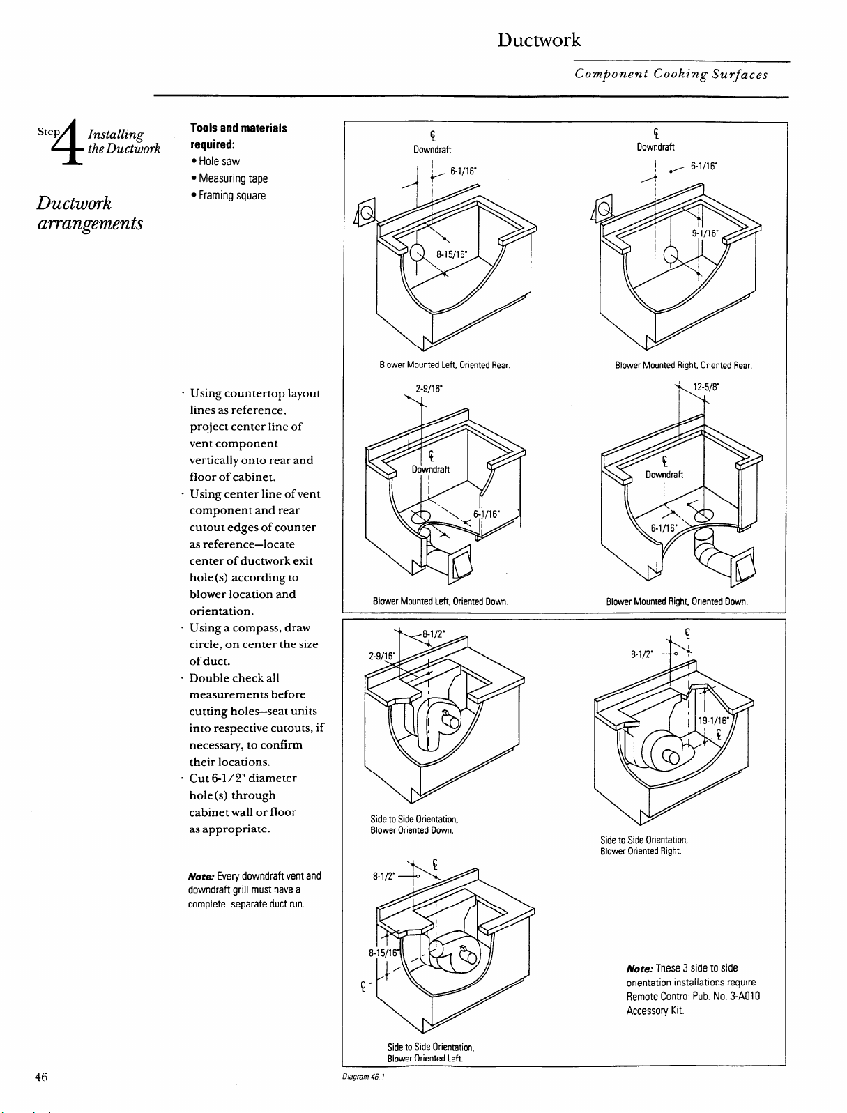
Ductwork
Component Cooking Surfaces
4
Step
Installing
Tools and materials
the Ductwork
required:
● Hole saw
s Measuring tape
Ductwork
s Framing square
arrangements
“ Using countertop layout
lines as reference,
project center line of
vent component
vertically onto rear and
floor of cabinet.
“ Using center line of vent
component and rear
cutout edges of counter
as reference—locate
center of ductwork exit
hole(s) according to
blower location and
orientation.
- Using a compass, draw
circle, on center the size
of duct.
“ Double check all
measurements before
cutting holes—seat units
into respective cutouts, if
necessary, to confirm
their locations.
“ Cut 6-1/2” diameter
hole(s) through
cabinet wall or floor
as appropriate.
~ore: Every downdraft vent and
downdraft grill must have a
complete, separate duct run.
!
$
Downdraft
Downdraft
1
Blower Mounted left, Oriented Rear
Blower Mounted Right, Oriented Rear.
Blower Mounted Left, Oriented Down
Blower Mounted Right, Oriented Down.
Side to Side Orientation,
Blower Oriented Down.
Side to Side Orientation,
Blower Oriented Right.
8zyxwvutsrqponmlkjihgfedcbaZYXWVUTSRQPONMLKJIHGFEDCBA
Note:
These 3 side to side
!“
orientation installations require
Remote Control Pub. No. 3-AO1 O
Accessory Kit.
Side to Side Orientation,
Blower Oriented Left.
46
D/agrarn 46 ?
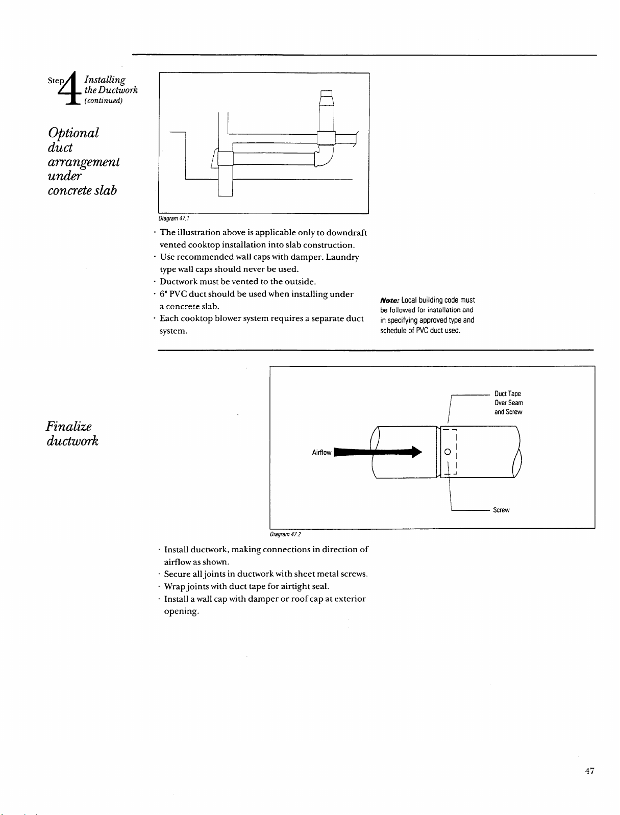
4
Step
Installing
the Ductwork
(continued)
II
Optional
duct
arrangement
under
concreteslab
Finalize
ductwork
Diagram 471
“ The illustration above is applicable only to downdraft
vented cooktop installation into slab construction.
“ Use recommended wall caps with damper. Laundry
type wall caps should never be used.
- Ductwork must be vented to the outside.
. 6“ PVC duct should be used when installing underzyxwvutsrqponmlkjihgfedcbaZYXWVUTSRQPONMLKJIHGFEDCBA
Note: Localbuilding code must
a concrete slab.
be followed for installation and
. Each cooktop blower system requires a separate duct
in specifying approved type and
system.
schedule of PVC duct used.
Airflow
+5
r
Duct Tape
Over Seam
and Screw
L
Screw
Diagram 472
. Install ductwork, making connections in direction of
airflow as shown.
. Secure all joints in ductwork with sheet metal screws.
. Wrap joints with duct tape for airtight seal.
. Install a wall cap with damper or roof cap at exterior
opening.
47
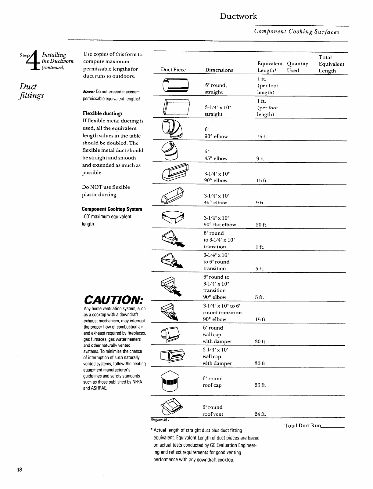
Ductwork
Component Cooking Surfaces
4
Step
Installing
the Ductwork
(continued)
Duct
fittings
Use copies of this form to
compute maximum
permissible lengths for
duct runs to outdoors.zyxwvutsrqponmlkjihgfedcbaZYXWVUTSRQPONMLKJIHGFEDCBA
Note: Do not exceed maximum
permissible equivalent lengths!
Flexible dueting
If flexible metal ducting is
used, all the equivalent
length values in the table
should be doubled. The
flexible metal duct should
be straight and smooth
and extended as much as
possible.
Do NOT use flexible
plastic ducting.
Component Cooktop System
100’ maximum equivalent
length
CAUTION:
Any home ventilation system, such
as a cooktop with a downdraft
exhaust mechanism, may interrupt
the proper flow of combustion air
and exhaust required by fireplaces,
gas furnaces, gas water heaters
and other naturally vented
systems. To minimize the chance
of interruption of such naturally
vented systems, follow the heating
equipment manufacturer’s
guidelines and safety standards
such as those published by NFPA
and ASHRAE.
Total
Equivalent Quantity
Equivalent
Duct Piece
Dimensions
Length* Used Length
m
1 ft.
6“ round,
(per foot
straight
length)
)
1 ft.
3-1/4” x 1
o“
(per foot
v /
straight length)
Q
6“
90° elbow 15 ft.
@
~,1
45° elbow 9 ft.
@
3-1/4” x 1o“
90° elbow
15 ft.
Q
3-1/4” x lo”
45° elbow 9 ft.
Ga
3-1/4” x 1o“
90° flat elbow 20 ft.
%
6“
round
to .3-1/4” x 1o“
transition
1 ft.
4
3-1/4” x lo”
to 6“ round
transition 5 ft.
%
6“ round to
%1/4” x lo”
transition
90° elbow
5 ft.
Q
3-1/4” X 10” to 6“
round transition
90° elbow 15 ft.
@
6“ round
wall cap
with damper
30 ft.
m
3-1/4” x 1o“
wall cap
with damper
30 ft.
@
6“ round
roof cap
26 ft.
@
6“ round
roof vent 24 ft.
Llagrarn
481
Total Duct Run_
● Actual length of straight duct plus duct fitting
equivalent. Equivalent Length of duct pieces are based
on actual tests conducted by GE Evaluation Engineer-
ing and reflect requirements for good venting
performance with any downdraft cooktop.
48
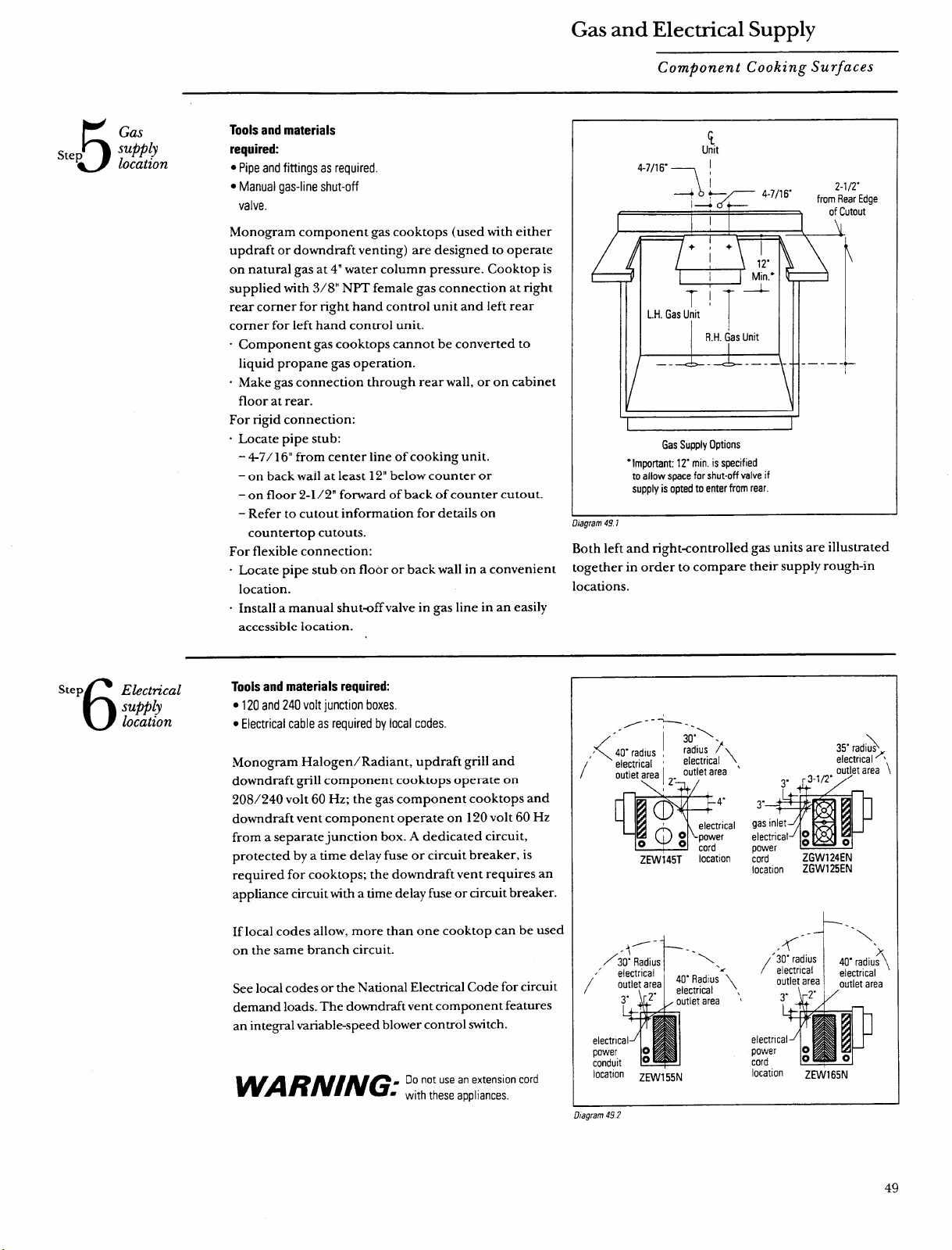
Gas and Electrical Supply
Component Cooking Surfaces
5
Gas
Step
supply
location
Tools and materials
required:
● Pipe and fittings as required.
● Manual gas-line shut-off
valve.
Monogram component gas cooktops (used with either
updraft or downdraft venting) are designed to operate
on natural gas at 4“ water column pressure. Cooktop is
supplied with 3/8” NPT female gas connection at right
rear corner for right hand control unit and left rear
corner for left hand control unit.
. Component gas cooktops cannot be converted to
liquid propane gas operation.
“ Make gas connection through rear wall, or on cabinet
floor at rear.
For rigid connection:
“ Locate pipe stub:
- 47/1 6“ from center line of cooking unit.
– on back wall at least 12” below counter or
– on floor 2-1/2” forward of back of counter cutout.
– Refer to cutout information for details on
ge
Gas Supply Options
‘Important 12- min. is specified
to allow space for shut-off valve if
supply is opted to enter from rear.
.“ .
uiagram 4YI
countertop cutouts.
For flexible connection:
Both left and right-controlled gas units are illustrated
. Locate pipe stub on floor or back wall in a convenient
togetherinordertocomparetheir supply rough-in
location.
locations.
. Install a manual shut-off valve in gas line in an easily
accessible location.
6
Step
Electrical
Tools and materials required:
supply
● 120and 240 volt junction boxes.
location
● Electrical cable as required by local codes.
Monogram Halogen/Radiant, updraft grill and
downdraft grill component cooktops operate on
208/240 volt 60 Hz; the gas component cooktops and
downdraft vent component operate on 120 volt 60 Hz
from a separate junction box. A dedicated circuit,
protected by a time delay fuse or circuit breaker, is
required for cooktops; the downdraft vent requires an
appliance circuit with a time delay fuse or circuit breaker.
If local codes allow, more than one cooktop can be used
on the same branch circuit.
See local codes or the National Electrical Code for circuit
demand loads. The downdraft vent component features
an integral variable-speed blower control switch.
/--?-.
.-
<
~o.\ ,
/zyxwvutsrqponmlkjihgfedcbaZYXWVUTSRQPONMLKJIHGFEDCBA
40”radius ,
/
radius #
[
electrical ‘
electrical
\
outlet area I -. ‘Utlet area ‘
Z17!i$
IL
(p
4“
electrical
~ power
o
cord
zEvvi45T
location
/’
~’\
a’
e
P
c
locat’on ZEW155N
\
35” radius
electrical”,
-1-
Y-- i
-.,,
AR’;;::;;;l~i
outlet area
‘1” \r2” I /out’etarea
electric
power
cord
location
ZEW165N
Dtagram 49 Z
49
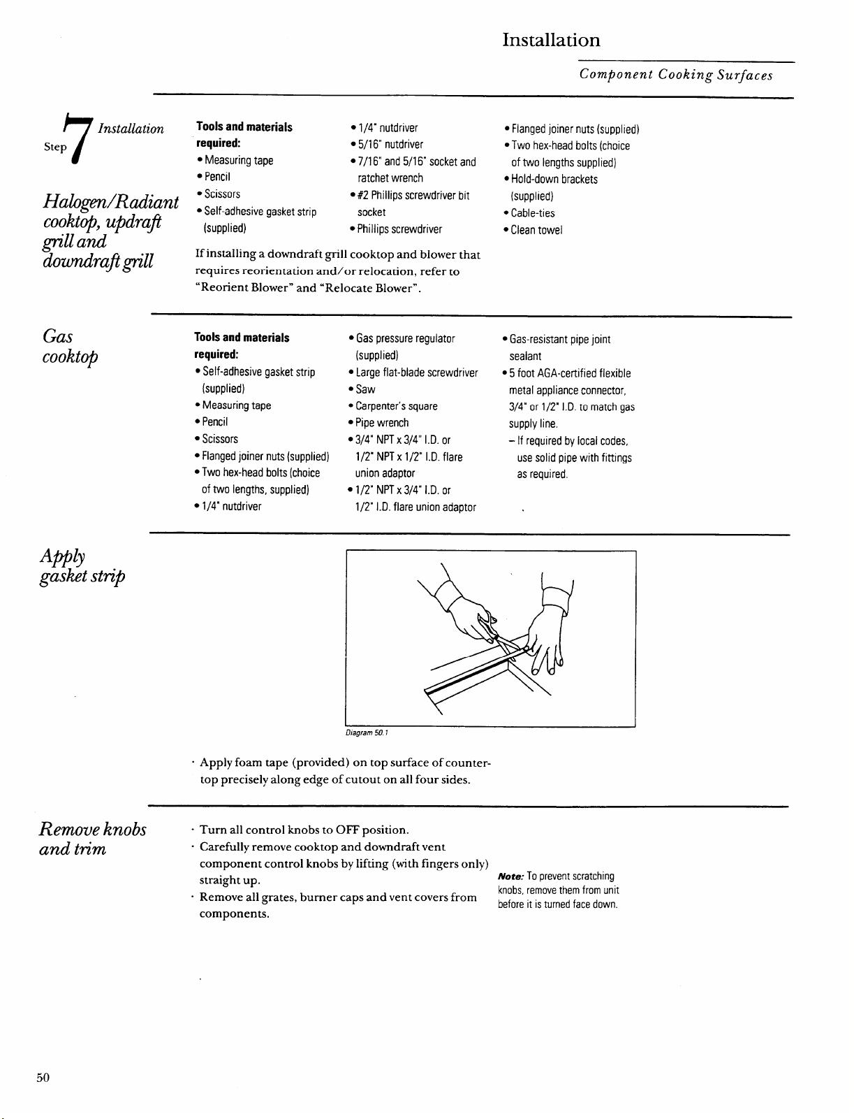
Installation
Component Cooking Surfaces
7
Installation
Tools and materials
● 1/4” nutdriver
● Flanged joiner nurs (supplied)
Step
required:
●5/16° nutdriver QTwo hex-head bolts (choice
● Measuring tape ● 7/16“ and 5/16” socket and
of two lengths supplied)
● Pencil
ratchet wrench
● Hold-down brackets
Halogm/Radiant I$&’~eSivegasketStrip
● #2 Phillips screwdriver bit
(supplied)
cookt+, updra~ -
socket
● Cable-ties
(supplied)
● Philiips screwdriver
● Clean towel
grz”lland
doumdrafip”ll
If installing a downdraft grill cooktop and blower that
requires reorientation and/or relocation, refer to
“ReOtient Blowern and “Relocate Blower”.
Gas
cookt~
Tools and materials
required:
● Self-adhesive gasket strip
(supplied)
● Measuring tape
● Pencil
● Scissors
● Flanged joiner nuts (supplied)
● Two hex-head bolts (choice
of two lengths, supplied)
● 1/4” nutdriver
● Gas pressure regulator
(supplied)
● Largeflat-blade screwdriver
● Saw
● Carpenter’s square
● Pipe wrench
● 3/4” NPT x 3/4” I.D. or
1/2” NPT x 1/2” I.D. flare
union adaptor
● 1/2” NPT x 3/4” I.D. or
1/2” I.D. flare union adaptor
● Gas-resistant pipe joint
sealant
● 5 foot AGA-certified flexible
metal appliance connector,
3/4” or 1/2’ I.D. to match gas
supply line.
- If required by local codes,
use solid pipe with fittings
as required.
A@lj
gasketstrip
Llagfam 501
. Apply foam tape (provided) on top surface of counter-
top precisely along edge of cutout on all four sides.
Remove knobs “
and tm”m
.
.
Turn all control knobs to OFF position.
Carefully remove cooktop and downdraft vent
component control knobs by lifting (with fingers only)
straight up.zyxwvutsrqponmlkjihgfedcbaZYXWVUTSRQPONMLKJIHGFEDCBA
Note: To prevent scratching
Remove all grates, burner caps and vent covers from
knobs, remove them from unit
before it is turned face down.
components,
50
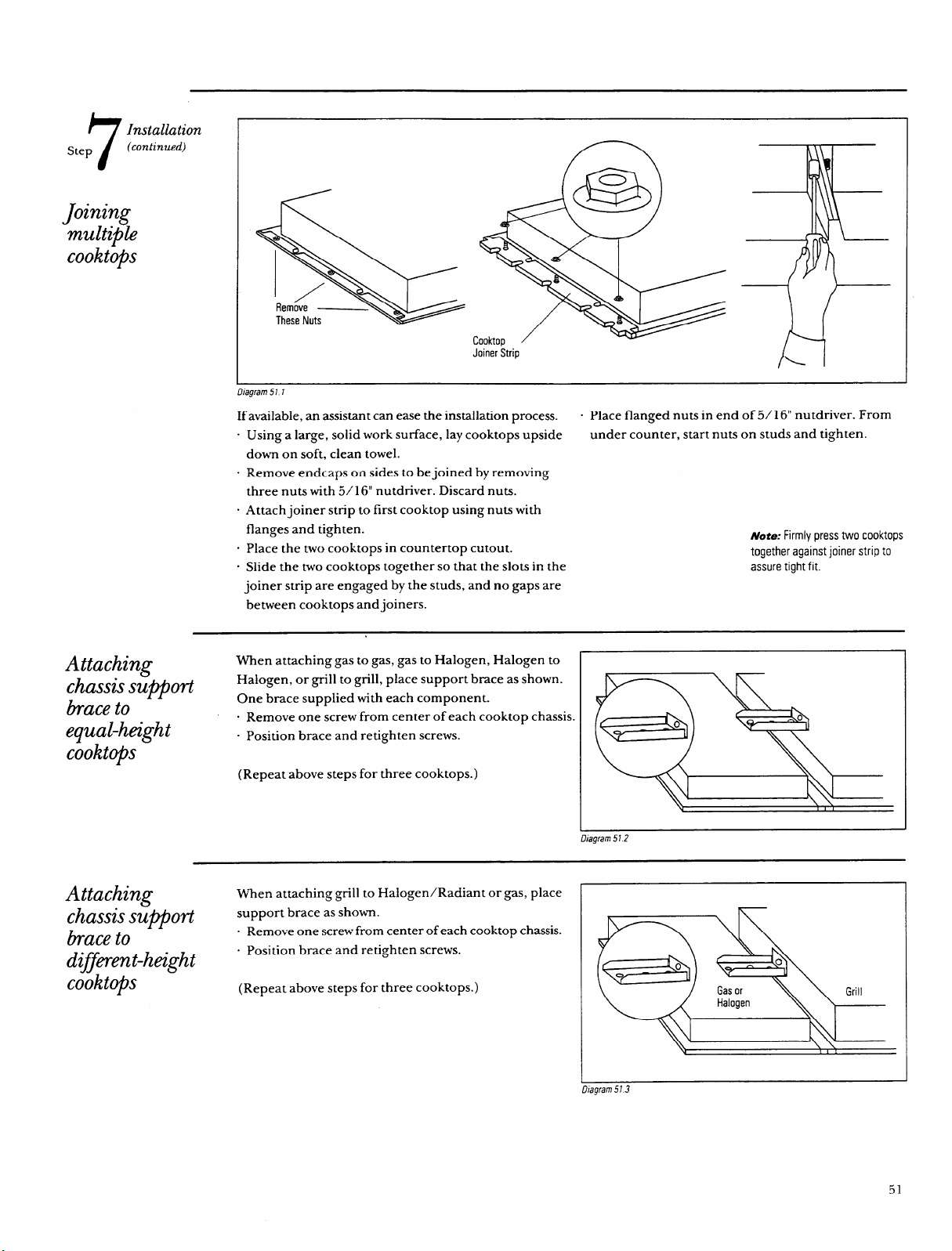
7
Installation
Step
(continued)
Jo~n@
multiple
cooktops
Remove —
These Nuts
Cooktop
Joiner Strip
H
D/agram57 7
If available, an assisrant can ease the installation process.
“ Place flanged nuts in end of 5/16“ nutdriver. From
“ Using a large, solid work surface, lay cooktops upside
under counter, start nuts on studs and tighten.
down on soft, clean towel.
. Remove endcaps on sides to be joined by removing
three nuts with 5/ 16“ nutdriver. Discard nuts.
. Attach joiner strip to first cooktop using nuts with
flanges and tighten.
- Place the two cooktops in countertop cutout.
- Slide the two cooktops together so that the slots in the
joiner strip are engaged by the studs, and no gaps are
between cooktops and joiners.
Note: Firmly press two cooktops
together against joiner strip to
assure tight fit.
Attachin~
When attaching gas to gas, gas to Halogen, Halogen to
chassiss;’oti
Halogen, or grill to grill, place support brace as shown.
braceto
One brace supplied with each component.
. Remove one screw from center of each cooktop chassis.
equal-height
- Position brace and retighten screws.
cookt@s
(Repeat above steps for three cooktops.)
gram 512
Attaching
When attaching grill to Halogen/Radiant or gas, place
chassissu~ort
support brace as shown.
braceto
. Remove one screw from center of each cooktop chassis.
d~jment-height
. Position brace and retighten screws.
cookto@
(Repeat above steps for three cooktops.)
hagrarn573
51
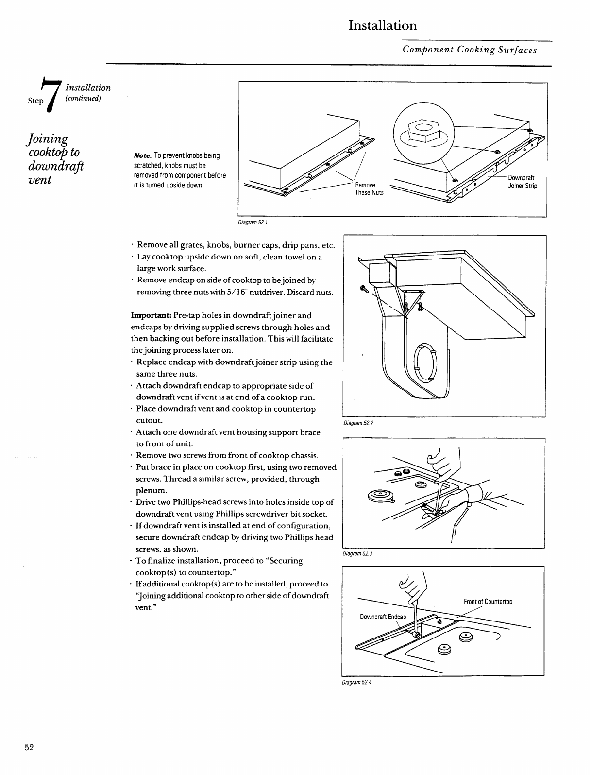
Installation
Component Cooking Surfaces
7
Installation
Step
(continued)
Jo~nW
cooktq ~“zyxwvutsrqponmlkjihgfedcbaZYXWVUTSRQPONMLKJIHGFEDCBA
Note: To prevent knobs being
downdrafi
scratched, knobs must be
vent
removed from component before
it is turned upside down.
D/agram521
. Remove all grates, knobs, burner caps, drip pans, etc.
“ Lay cooktop upside down on soft, clean towel on a
large work surface.
s Remove endcap on side ofcooktop to bejoined by
removing three nuts with 5/ 16“ nutdnver. Discard nuts.
Important: Pre-tap holes in downdraft joiner and
endcaps by driving supplied screws through holes and
then backing out before installation. This will facilitate
the joining process later on.
- Replace endcap with downdraftjoiner strip using the
same three nuts.
“ Attach downdraft endcap to appropriate side of
downdraft vent if vent is at end of a cooktop run.
- Place downdraft vent and cooktop in countertop
%)
i
cutout.
D/agram522
“ Attach one downdraft vent housing support brace
to front of unit.
. Remove two screws from front of cooktop chassis.
. Put brace in place on cooktop first, using two removed
screws. Thread a similar screw, provided, through
plenum.
Q
-
. Drive two Phillips-head screws into holes inside top of
downdraft vent using Phillips screwdriver bit socket.
. If downdraft vent is installed at end of configuration,
secure downdraft endcap by driving two Phillips head
screws, as shown.
Diagram 523
. To finalize installation, proceed to “Securing
cooktop(s) to countertop. ”
- If additional cooktop(s) are to be installed, proceed to
“Joining additional cooktop to other side of downdraft
Front of Countertop
vent. ”
Downdraft Endcap
D:agram524
52
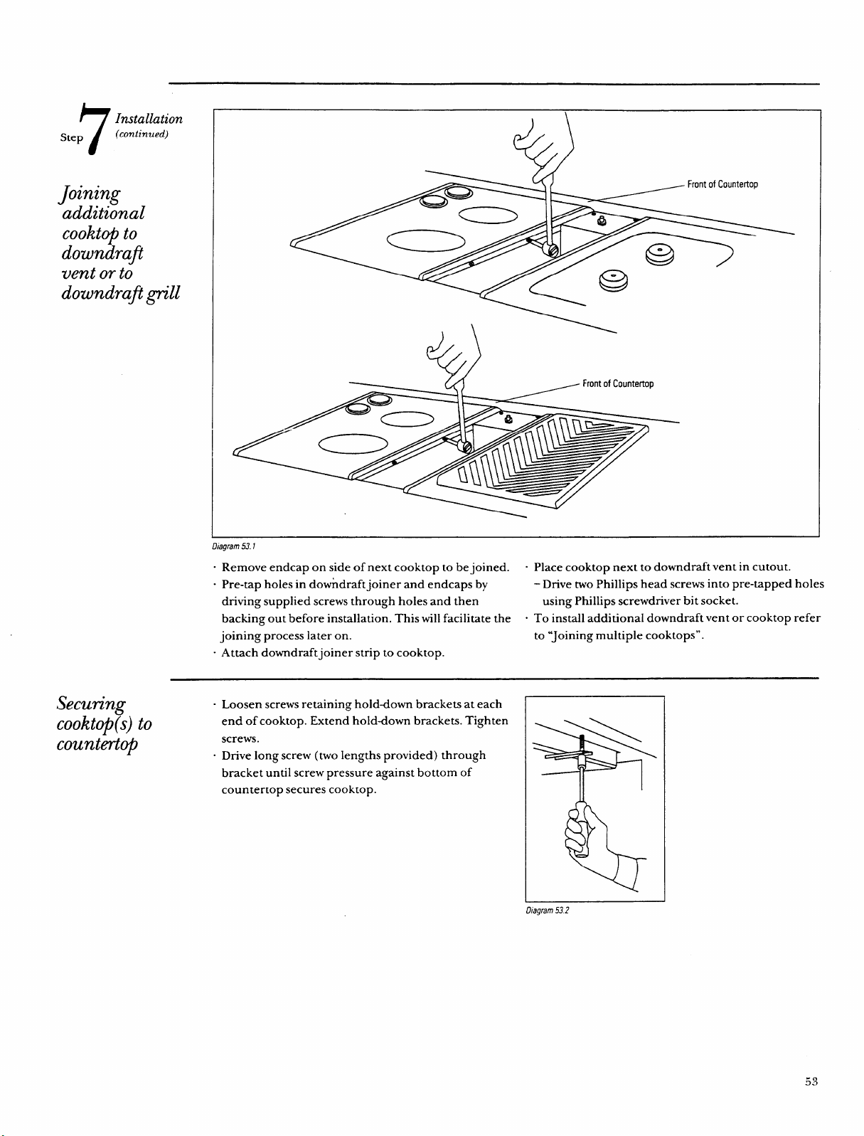
7
Installation
Step
(continued)
Jonung
additional
cooktopto
downdrafi
vent or to
downdrafi~“11
I
Securing
cooktop(s)to
countertop
42)
~ Front of Countertop
Diagram 53.1
“ Remove endcap on side of next cooktop to be joined.
“ Place cooktop next to downdraft vent in cutout.
“ Pre-tap holes in downdraft joiner and endcaps by
- Drive two Phillips head screws into pre-tapped holes
driving supplied screws through holes and then
using Phillips screwdriver bit socket.
backing out before installation. This will facilitate the
“ To install additional downdraft vent or cooktop refer
joining process later on. to “Joining multiple coolitops”.
- Attach downdraftjoiner strip to cooktop.
“ Loosen screws retaining holddown brackets at each
I
end of cooktop. Extend holddown brackets. Tighten
I \\\
screws.
o Drive long screw (two lengths provided) through
bracket until screw pressure against bottom of
=$==
countertop secures cooktop.
Llagram 53.?
53
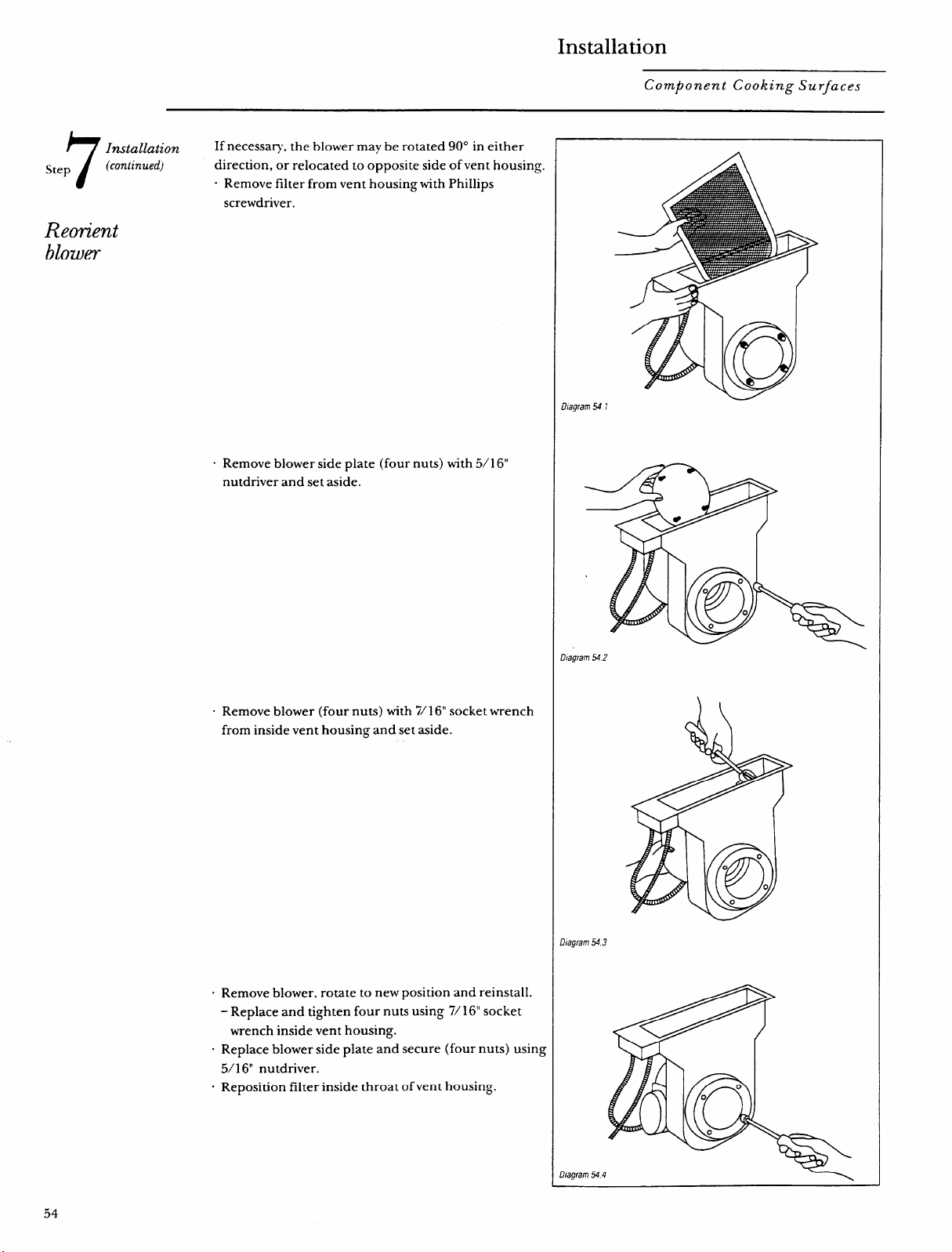
Installation
Component Cooking Surfaces
h
Installation
If necessary, the blower maybe rotated 90° k either
Step
/
(continued)
direction, or relocated to opposite side of vent housing.
“ Remove filter from vent housing with Phillips
screwdriver.
Reorient
blower
o Remove blower side plate
nutdriver and set aside.
(four nuts) with 5/1 6“
. Remove blower (four nuts) with 7/16“ socket wrench
from inside vent housing and set aside.
“ Remove blower, rotate to new position and reinstall.
- Replace and tighten four nuts using 7/ 16“ socket
wrench inside vent housing.
- Replace blower side plate and secure (four nuts) using
5/1 6“ nutdriver.
“ Reposition filter inside throat of vent housing.
D/agram 541
Diagram S42
Dfagram543
!hagram544
54
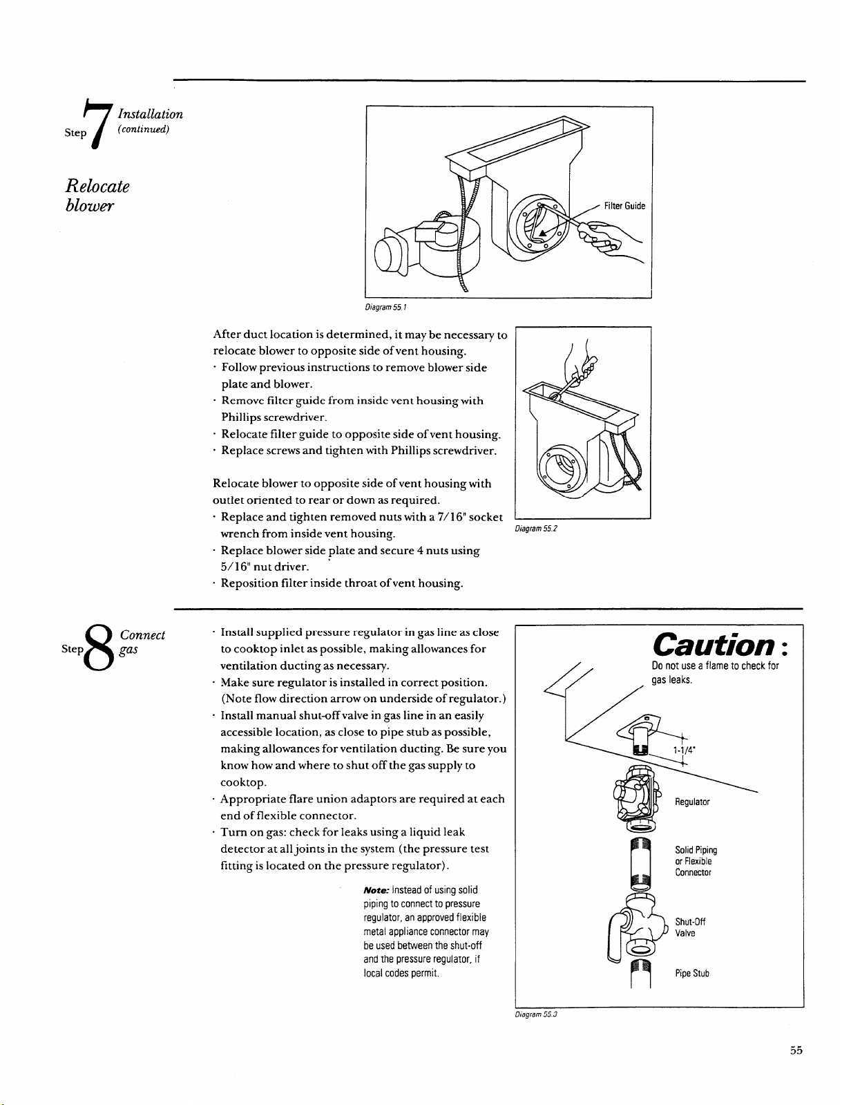
7
Step
Installation
(continued)
Relocate
blowe?-
Dfagram 551
After duct location is determined, it may be necessary to
relocate blower to opposite side of vent housing.
“ Follow previous instructions to remove blower side
plate and blower.
o Remove filter guide from inside vent housing with
Phillips screwdriver.
“ Relocate filter guide to opposite side of vent housing.
. Replace screws and tighten with Phillips screwdriver.
Relocate blower to opposite side of vent housing with
outlet oriented to rear or down as required.
. Replace and tighten removed nuts with a 7/1 6“ socket ~
wrench from inside vent housing.
Diagram 55.?
. Replace blower side plate and secure 4 nuts using
5/1 6“ nut driver. ‘
. Reposition filter inside throat of vent housing.
8
Connect
Step
gas
.
.
.
Install supplied pressure regulator in gas line as close
to cooktop inlet as possible, making allowances for
ventilation ducting as necessary.
Make sure regulator is installed in correct position.
(Note flow direction arrow on underside of regulator.)
Install manual shut-off valve in gas line in an easily
accessible location, as close to pipe stub as possible,
making allowances for ventilation ducting. Be sure you
know how and where to shut off the gas supply to
cooktop.
Appropriate flare union adaptors are required at each
end of flexible connector.
Turn on gas: check for leaks using a liquid leak
detector at all joints in the system (the pressure test
fitting is located on the pressure regulator).zyxwvutsrqponmlkjihgfedcbaZYXWVUTSRQPONMLKJIHGFEDCBA
Note: Instead of using solid
piping to connect to pressure
regulator, an approved flexible
metal appliance connector may
be used between the shut-off
and the pressure regulator, if
local codes permit.
Caution z
/.
Do not use a flame to check for
Y /gas’eaks’
n
Solid Piping
or Flexible
I!!4
Connector
&
@
n
Shut-Off
Valve
Pipe Stub
fagram553
55
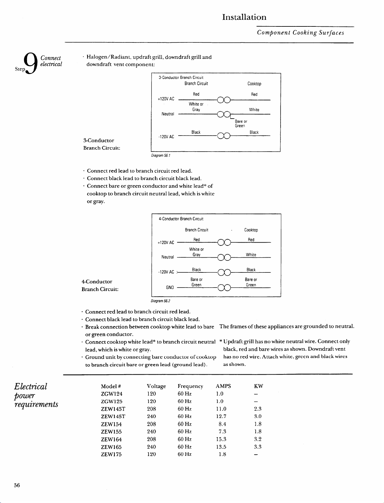
Installation
Component Cooking Surfaces
9
Step
Connect
“ Halogen/Radiant, updraft grill, downdraft grill and
electn”cal
downdraft vent component:
3-Conductor Branch Circu]t
Branch Circuit
Cooktop
Electrical
P
owe?-
requirements
.3-Conductor
Red Red
+120V AC
White or
Gray
White
Neutral
Bare or
Green
Black Black
-120VAC
Branch Circuit:
\
J
Lhagram 56.1
“ Connect red lead to branch circuit red lead.
“ Connect black lead to branch circuit black lead.
o Connect bare or green conductor and white lead* of
cooktop to branch circuit neutral lead, which is white
or gray.
4-Conductor Branch Clrcuh
Branch C[rcuit
Cooktop
Red Red
+120V AC
White or
I
Neutral
Gray
White
-120VAC :
Black
Black
4Conductor
Bare or
Bare or
GND
Green
Green
Branch Circuit:
1
Llagram 56.2
“ Connect red lead to branch circuit red lead.
- Connect black lead to branch circuit black lead.
. Break connection between cooktop white lead to bare
The frames of these appliances are grounded to neutral.
or green conductor.
. Connect cooktop white lead* to branch circuit neutral
* Updraft grill has no white neutral wire. Connect only
lead, which is white or gray.
black, red and bare wires as shown. Downdraft vent
“ Ground unit by connecting bare conductor of cooktop
has no red wire. Attach white, green and black wires
to branch circuit bare or green lead (ground lead).
as shown.
,Model #
ZGW124
ZGW125
ZEW145T
ZEW145T
ZEW154
ZEW155
ZEW164
ZEWI 65
ZEW175
Voltage
120
120
208
240
208
240
208
240
120
Frequency
60 Hz
60 Hz
60 Hz
60 Hz
60 Hz
60 Hz
60 Hz
60 Hz
60 Hz
AMPS
1.0
1.0
11.0
12.7
8.4
7.3
15.3
13.5
1.8
Kw
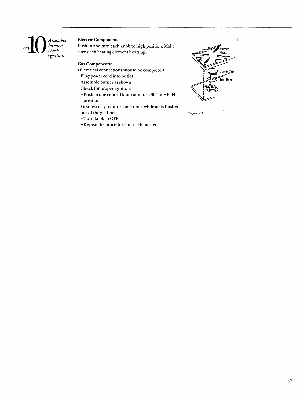
10
Assemble
Step
burners,
ctick
ignition
Electric Components:
Push in and turn each knob to high position. Make
sure each heating element heats up.
Gas Components:
(Electrical connections should be complete.)
“ Plug power cord into outlet.
“ Assemble burner as shown.
“ Check for proper ignition:
- Push in one control knob and turn 90° to HIGH
position.
“ First test may require some time, while air is flushed
out of the gas line:
- Turn knob to OFF.
– Repeat the procedure for each burner.
?Bumer
< W Grate
I
E-’
~Trim Ring
1
Dfagram571
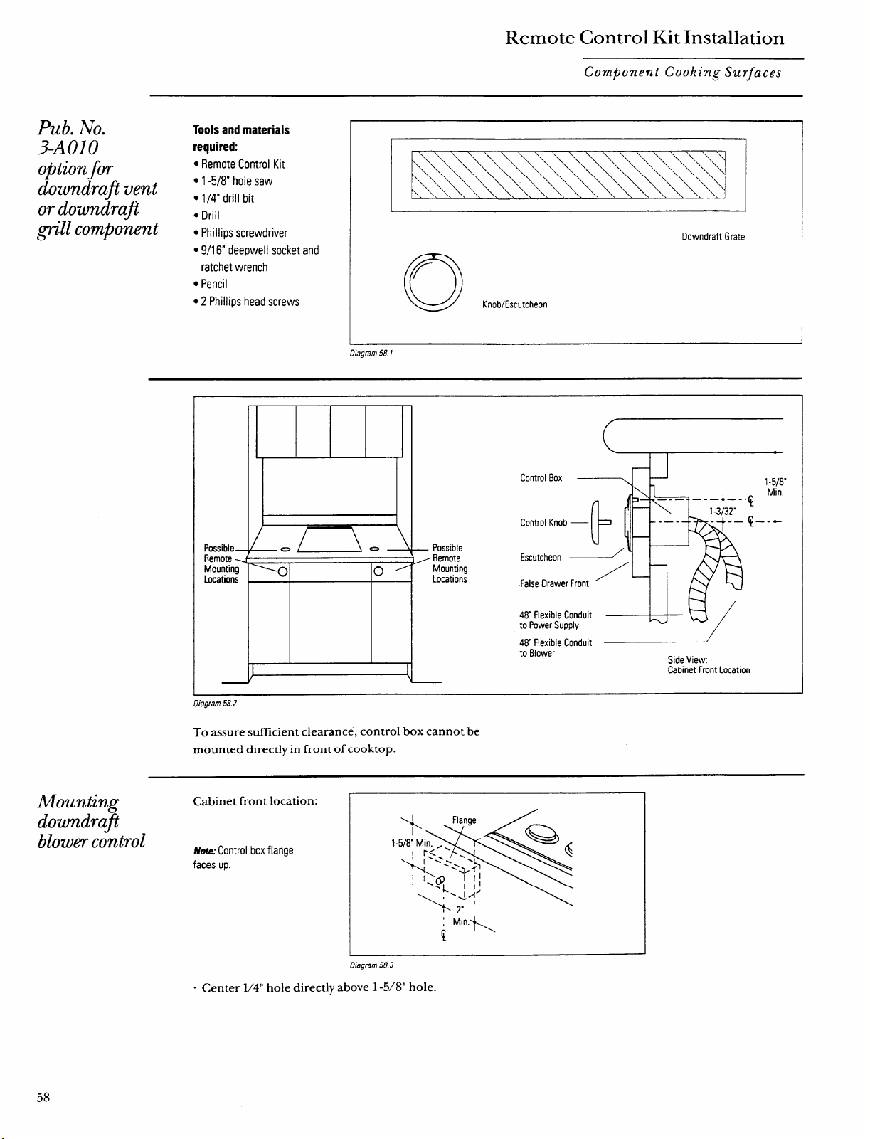
Remote Control Kit Installation
Component Cooking Surfaces
Pub. No.
3-AO1O
Tools and materials
required:
optionfor
. Remote Control Kit
downdrafivent
● 1-5/8” hole saw
● 1/4” drill bit
or downdrafi
. Drill
\
~“11component
cPhillips screwdriver
● 9/16“ deepwell socket and
ratchet wrench
s Pencil
● 2 Phillips head screws
Uagram w 1
Mounting
downdra@
blowercontrol
Downdraft Grate
c1
/-
Knob/Escutcheon
Possible
Remote
Mounting
Locations
Control Box —.
m
Cohtrol Knob
Escutcheon
False Drawer
I
1-5/8”
$
Min.
$–-
IzyxwvutsrqponmlkjihgfedcbaZYXWVUTSRQPONMLKJIHGFEDCBA
48”Flexible Conduit
to Power Supply
--Q-u/
to Blower
Side View:
Cabinet Front Location
-. ---
ulagram Mf.z
To assure sufficient clearance, control box cannot be
mounted directly in front of cooktop.
Cabinet front location:
Note: Control box flange
faces up.
D/agram 58.3
“ Center l/4° hole directly above 1 -5/8” hole.
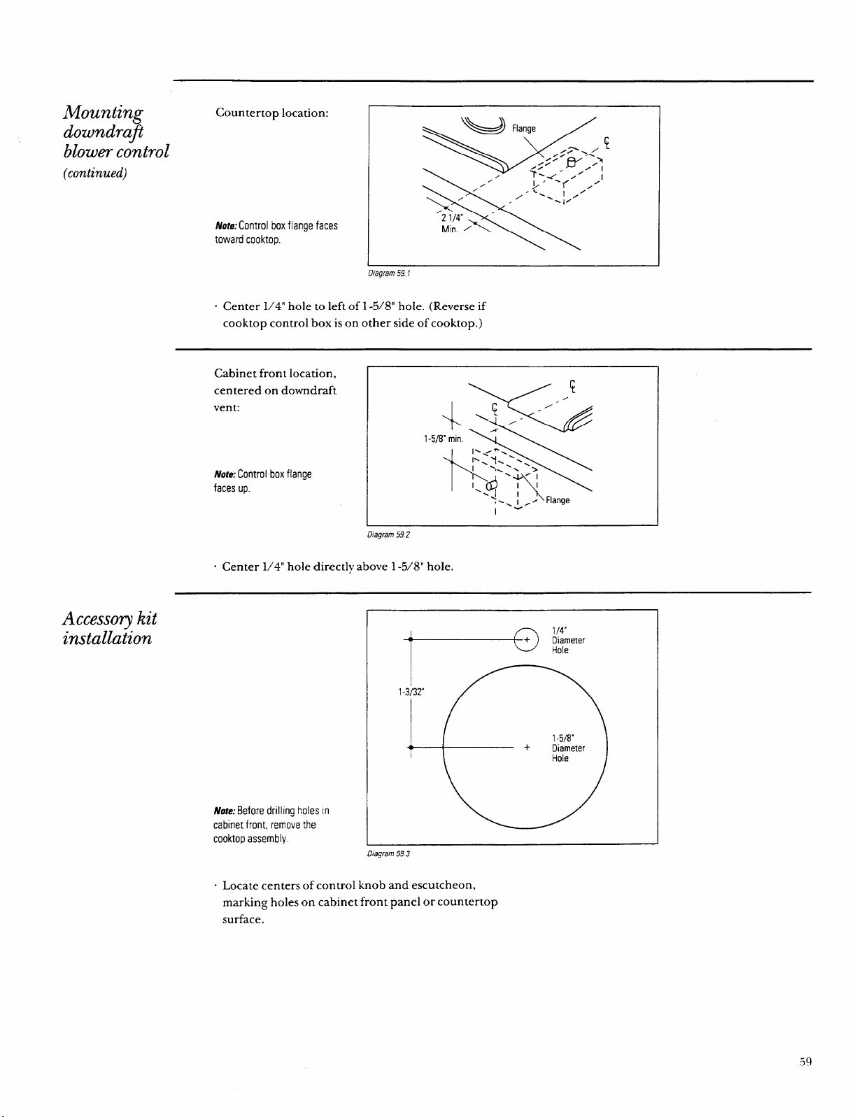
Mounting
downdrafi
blowercontrol
(continued)
Countertop location:
fI/ote: Control box flange faces
toward cooktop.
Diagram 59.1
“ Center 1/4” hole to left of 1-5/8” hole. (Reverse if
cooktop control box is on other side of cooktop. )
Cabinet front location,
centered on downdraft
vent:
Note; Control box flange
faces up.
Diagram 59.2
“ Center 1/4” hole directly above 1 -5/8” hole
Accesso~ kit
installationzyxwvutsrqponmlkjihgfedcbaZYXWVUTSRQPONMLKJIHGFEDCBA
Note:Before drilling holes [n
cabinet front, remove the
cooktop assembly.
I
1-3/32”
4“— —
+
Diameter
Dtagram593
“ Locate centers of control knob and escutcheon,
marking holes on cabinet front panel or countertop
surface.
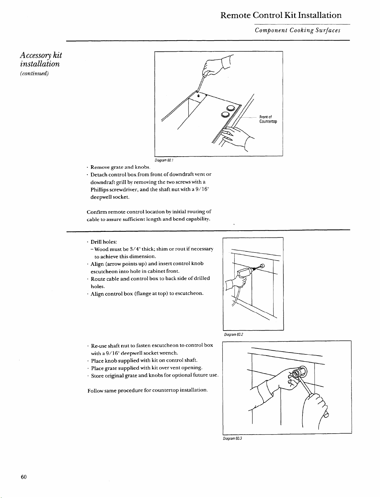
Remote Control Kit Installation
Component Cooking Surfaces
Accessorykit
installation
(continued)
D/agram 601
“ Remove grate and knobs.
“ Detach control box from front of downdraft vent or
downdraft grill by removing the two screws with a
Phillips screwdriver, and the shaft nut with a 9/ 16“
deepwell socket.
Front of
Countertop
Confirm remote control location by initial routing of
cable to assure sufficient length and bend capability.
- Drill holes:
– Wood must be 3/4” thick; shim or rout if necessary
to achieve this dimension.
“ Align (arrow points up) and insert control knob
escutcheon into hole in cabinet front.
- Route cable and control box to back side of drilled
holes.
“ Align control box (flange at top) to escutcheon.
“ Re-use shaft nut to fasten escutcheon to control box
with a 9/16“ deepwell socket wrench.
. Place knob supplied with kit on control shaft.
. Place grate supplied with kit over vent opening.
. Store original grate and knobs for optional future use.
Follow same procedure for countertop installation.
Dtagram 60.2zyxwvutsrqponmlkjihgfedcbaZYXWVUTSRQPONMLKJIHGFEDCBA
1
J
Dtagram 60.3
60

NOTES
61
With the purchase of your new Monogram appliance, receive the assurance that ifyou ever
need information or assistance born GE, we’ll be there. All you have to do is call—toll-free!
I!Home RepairSewicezyxwvutsrqponmlkjihgfedcbaZYXWVUTSRQPONMLKJIHGFEDCBA
801WE#ARES(801M32-2737)
AGE consumer service professional will provide expert repair service,
scheduled at a time that’s convenient for you. Many GE Consumer Service
company~perated locations offer you service today or tomorrow, or at your
convenience (7:00 a.m. to 7:00 p.m. weekdays, 9:00 a.m. to 2:00 p.m. Saturdays).
Our factory-trained technicians know your appliance inside and out–so most
repairs can be handled in just one visit.
GEAnswerCenter@
80/?6262000
Whatever your question about any Monogram major appliance, GE Answer
Center@ information service is available to help. Your call–and your question–
will be answered promptly and courteously. And you can call any time. GE
Answer Center@ service is open 24 hours a day, 7 days a week.
m- A-a
-.—-,..-”- -
--. -. —.. —..
ForCustomersW& SpecialNeeds...
80~62ti2000
Upon request, GE will provide
Braille controls for a variety of
Monogram appliances, and a
brochure to assist in planning a
barrier-free kitchen for persons
with limited mobility. To obtain
these items, free of charge, call
800.626.2000.
Consumers with impaired hearing or speech who have
access to a TDD or a conventional teletypewriter may
call 800-TDD-GEAC (800-833-4322) to request
information or service.
ServiceCbntiac&
80Wi21k2224
You can have the secure feeling that GE Consumer Service will still be there
after your warranty expires. Purchase a GE contract while your warranty is still
in effect and you’ll receive a substantial discount. With a multiple-year contract,
you’re assured of future semice at today’s prices.
PartkandAccessories
801M2&2002
Individuals qualified to service their own appliances
User maintenance instructions contained in this
can have needed partsor accessoriessent directlyto
booklet coverprocedures intended to be performed
theirhome. The GE parts system provides access to over
by any user. Other servicing generallyshould be
47,000
parts... and all GE Genuine Renewal Parts are
referred to qualifled service personnel. Caution
fully warranted. VISA, MasterCard and Discover cards
must be exercised, since improper servicing may
are accepted.
cause unsafe operation.
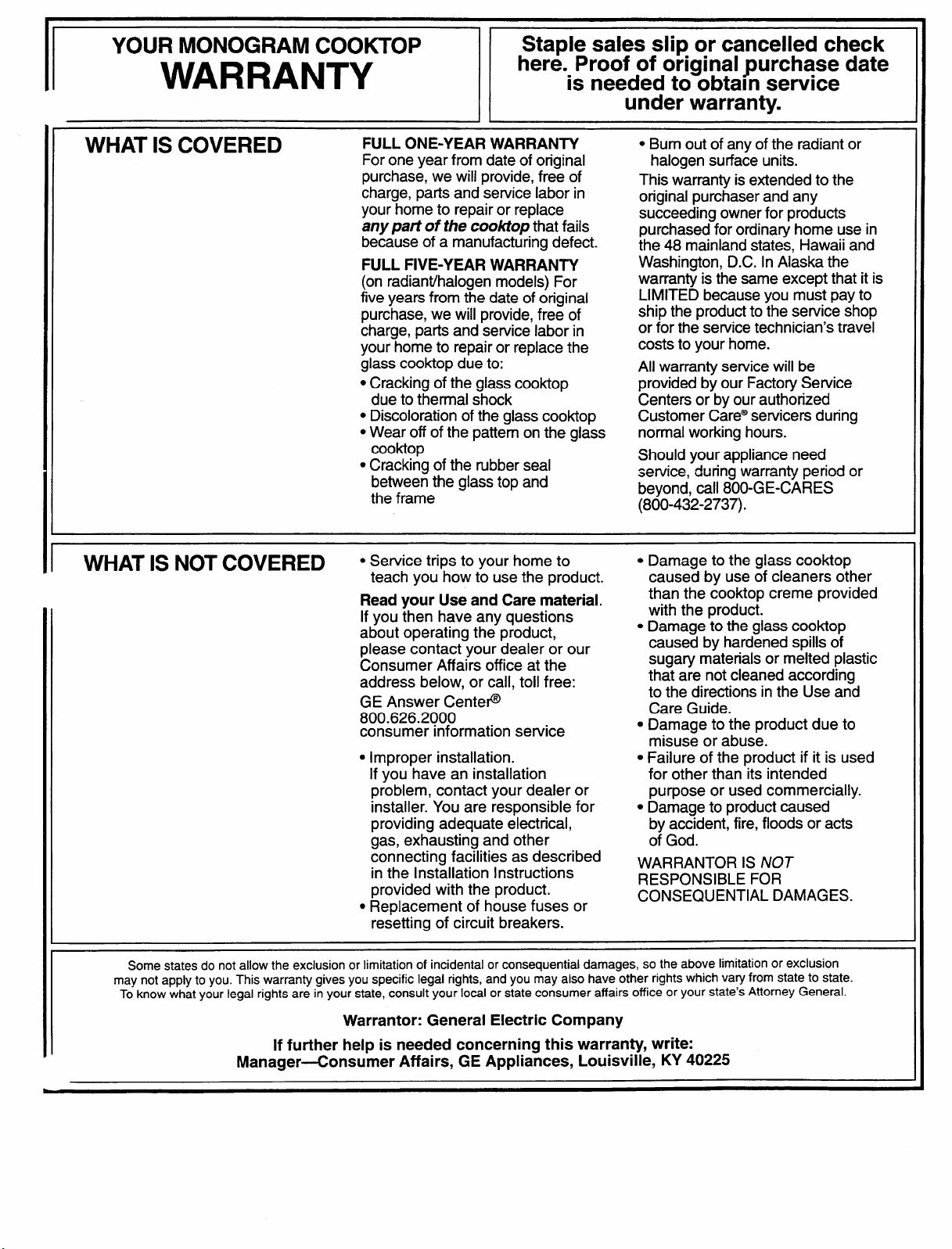
YOUR MONOGRAM COOKTOP
Staple sales slip or cancelled check
WARRANTY
here. Proof of original purchase date
is needed to obtain service
under warranty.
WHAT IS COVERED
FULL ONE-YEAR WARRANTY
For one year from date of original
purchase, we will provide, free of
charge, parts and setvice labor in
your home to repair or replacezyxwvutsrqponmlkjihgfedcbaZYXWVUTSRQPONMLKJIHGFEDCBA
my part of the cooktop that fails
because of a manufacturing defect.
FULL FIVE-YEAR WARRANTY
(on radiantihalogen models) For
five years from the date of original
purchase, we will provide, free of
charge, parts and service labor in
your home to repair or replace the
glass cooktop due to:
. Cracking of the glass cooktop
due to thermal shock
● Discoloration of the glass cooktop
. Wear off of the pattern on the glass
Cooktop
● Cracking of the rubber seal
between the glass top and
the frame
● Bum out of any of the radiant or
halogen surface units.
This warranty is extended to the
original purchaser and any
succeeding owner for products
purchased for ordinaty home use in
the 48 mainland states, Hawaii and
Washington, D.C. In Alaska the
warranty is the same except that it is
LIMITED because you must pay to
ship the product to the service shop
or for the sewice technician’s travel
costs to your home.
All warranty service will be
provided by our Factory Service
Centers or by our authorized
Customer Care@sewicers during
normal working hours.
Should your appliance need
sewice, during warranty period or
beyond, call 800-GE-CARES
(800-432-2737).
WHAT IS NOT COVERED
● Service trips to your home to
teach you how to use the product.
Read your Use and Care material.
If you then have any questions
about operating the product,
please contact your dealer or our
Consumer Affairs office at the
address below, or call, toll free:
GE Answer Center@
800.626.2000
consumer information service
c Improper installation.
If you have an installation
problem, contact your dealer or
installer. You are responsible for
providing adequate electrical,
gas, exhausting and other
connecting facilities as described
in the Installation Instructions
provided with the product.
s Replacement of house fuses or
resetting of circuit breakers.
● Damage to the glass cooktop
caused by use of cleaners other
than the cooktop creme provided
with the product.
c Damage to the glass cooktop
caused by hardened spills of
sugary materials or melted plastic
that are not cleaned according
to the directions in the Use and
Care Guide.
● Damage to the product due to
misuse or abuse.
● Failure of the product if it is used
for other than its intended
purpose or used commercially.
● Damage to product caused
by accident, fire, floods or acts
of God.
WARRANTOR IS NOT
RESPONSIBLE FOR
CONSEQUENTIAL DAMAGES.
Some states do not allow the exclusion or limitation of incidental or consequential damages, so the above limitation or exclusion
may not apply to you. This warranty gives you specific legal rights, and you may also have other rights which vary from state to state.
To know what your legal rights are in your state, consult your local or state consumer affairs office or your state’s Attorney General.
Warrantor: General Electric Company
If further help is needed concerning this warranty, write:
Manager-Consumer Affairs, GE Appliances, Louisville, KY 40225

-.
Pub. S(). 49-8487
Part So. 164D!?966POI 6
D-953-4994
6-94 cczyxwvutsrqponmlkjihgfedcbaZYXWVUTSRQPONMLKJIHGFEDCBA
Generel Electric Company
Louisville, KY 4%?25

