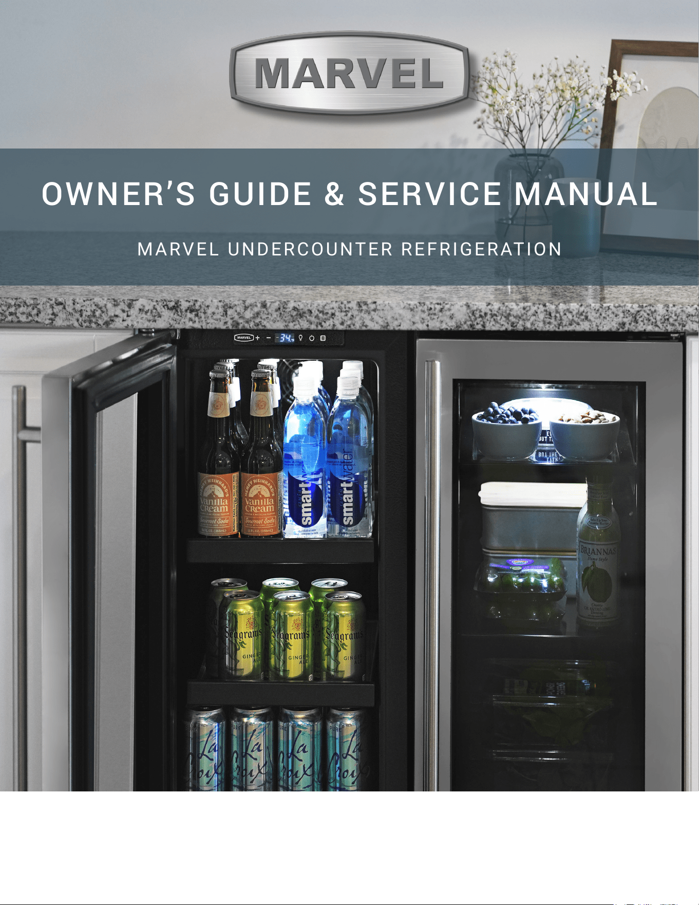
OWNER’S GUIDE & SERVICE MANUAL
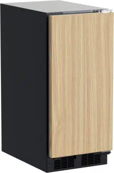
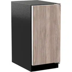
MARVEL UNDERCOUNTER REFRIGERATION
Model: MLCP215-SS81A
WELCOME
Welcome to the Marvel Experience!
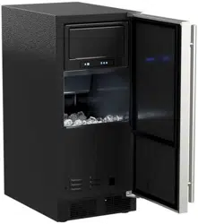
Congratulations on your purchase of the industry’s quietest
clear ice machine with the best ice clarity and purity. Your
new investment is protected by a limited warranty for the
rst year, and hermetically sealed refrigeration system parts
are covered for an additional 4 years.
Here’s your guide to the operation and maintenance of your
Marvel Clear Ice Machine to ensure years of enjoyment. If
you have any questions, please contact Marvel Customer
Service or Tech Support at:
Phone: (616) 754-5601
Email:
Got a Marvelous Design?
We would love to see how your Marvel product looks in its
new home. You can send us photos of your installed
might feature your Marvel home design on our website and
social media!
Warranty Registration
It is important you register your product warranty after
taking delivery of your appliance. You can register online at
www.marvelrefrigeration.com.
The following information will be
required when registering your
appliance:
Serial Number
Date of Purchase
Dealer’s name and address
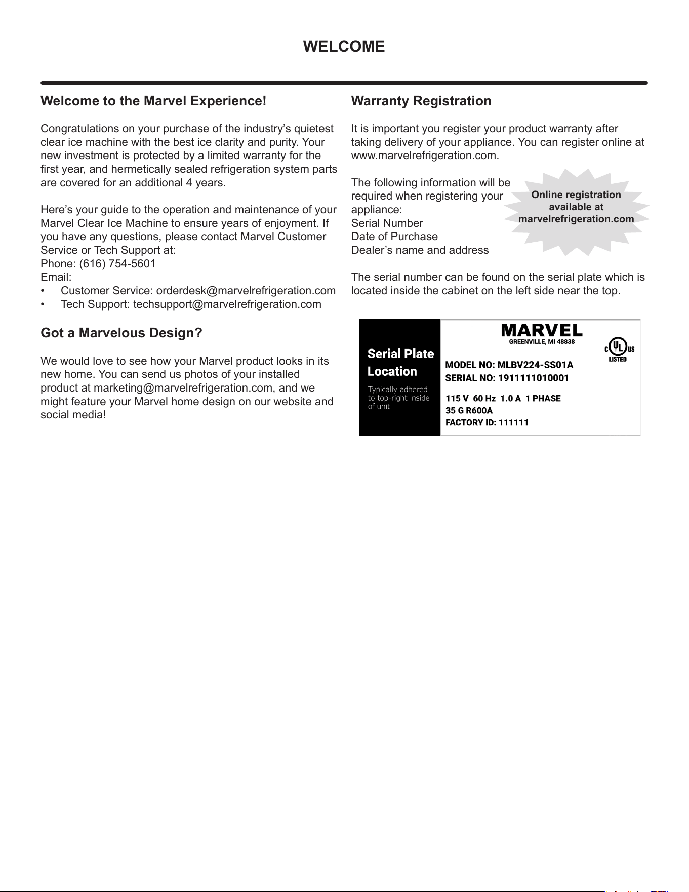
The serial number can be found on the serial plate which is
located inside the cabinet on the left side near the top.
Online registration
available at
marvelrefrigeration.com

TABLE OF CONTENTS
Tip: Click on any section below to jum
p directly there
Safety
Important Safety Instructions
Installation
Unpacking Your Appliance
Electrical
Cutout & Product Dimensions
Side-by-Side & Stacking Installations
Door Reversal
Installing The Water Supply
Maintenance
Care and Cleaning
Long-Term Storage/Winterization
Operating Instructions
Using Your Electronic Control
Ice Maker Operation
Service
Obtaining Service
Troubleshooting
Wire Diagram
Warranty Claims
Parts List
Ordering Replacement Parts
System Diagnosis Guide
Compressor Specifications
Control Operation - Service
Thermistor
Warranty
3
IMPORTANT SAFETY INSTRUCTIONS
Important Safety Instructions
Warnings and safety instructions appearing in this guide
are not meant to cover all possible conditions and
situations that may occur. Common sense, caution and
care must be exercised when installing, maintaining or
operating this appliance.
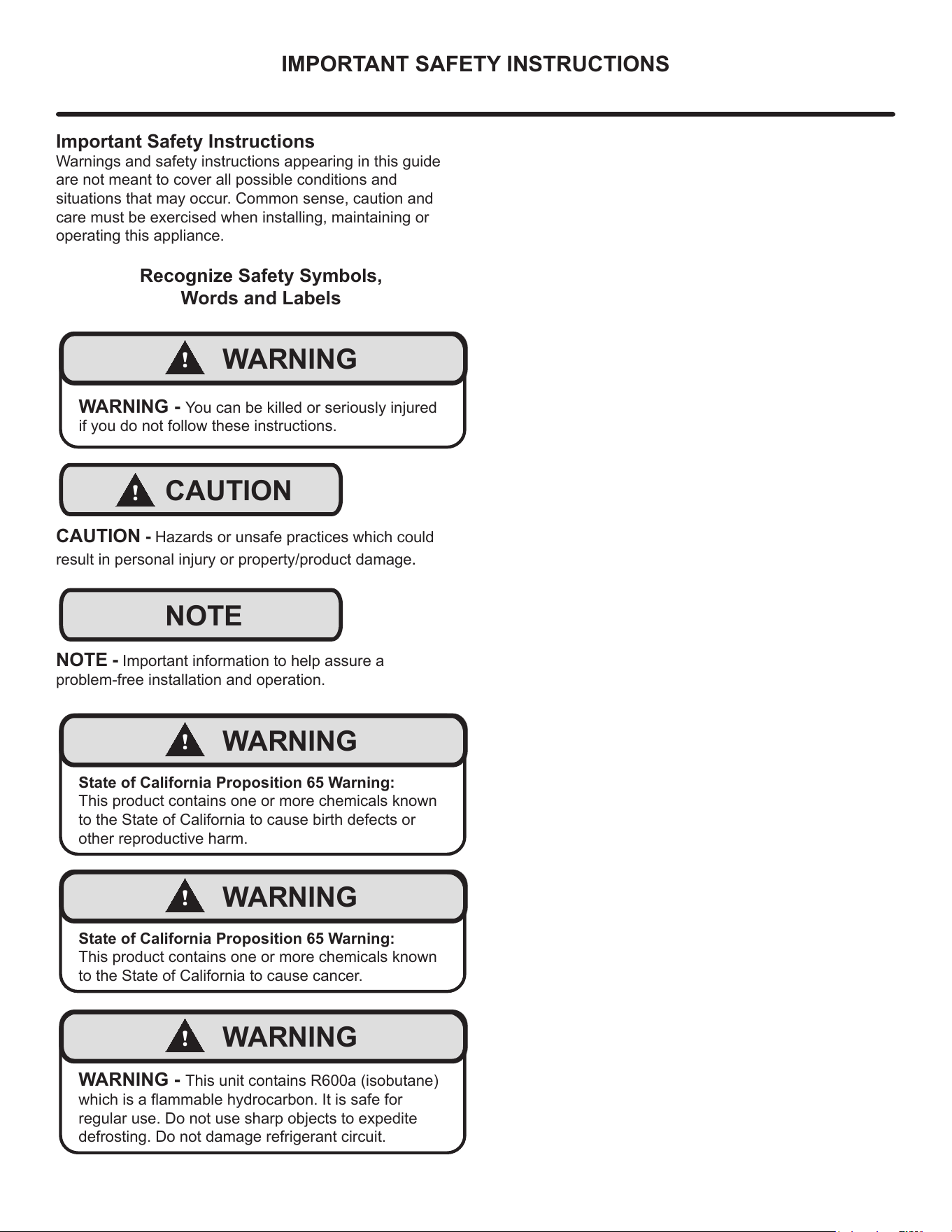
Recognize Safety Symbols,
Words and Labels
!
WARNING
WARNING - You can be killed or seriously injured
if you do not follow these instructions.
!
CAUTION
CAUTION - Hazards or unsafe practices which could
result in personal injury or property/product damage.
NOTE
NOTE - Important information to help assure a
problem-free installation and operation.
!
WARNING
State of California Proposition 65 Warning:
This product contains one or more chemicals known
to the State of California to cause birth defects or
other reproductive harm.
!
WARNING
State of California Proposition 65 Warning:
This product contains one or more chemicals known
to the State of California to cause cancer.
!
WARNING
WARNING - This unit contains R600a (isobutane)
which is a ammable hydrocarbon. It is safe for
regular use. Do not use sharp objects to expedite
defrosting. Do not damage refrigerant circuit.
4
UNPACKING YOUR APPLIANCE
!
WARNING
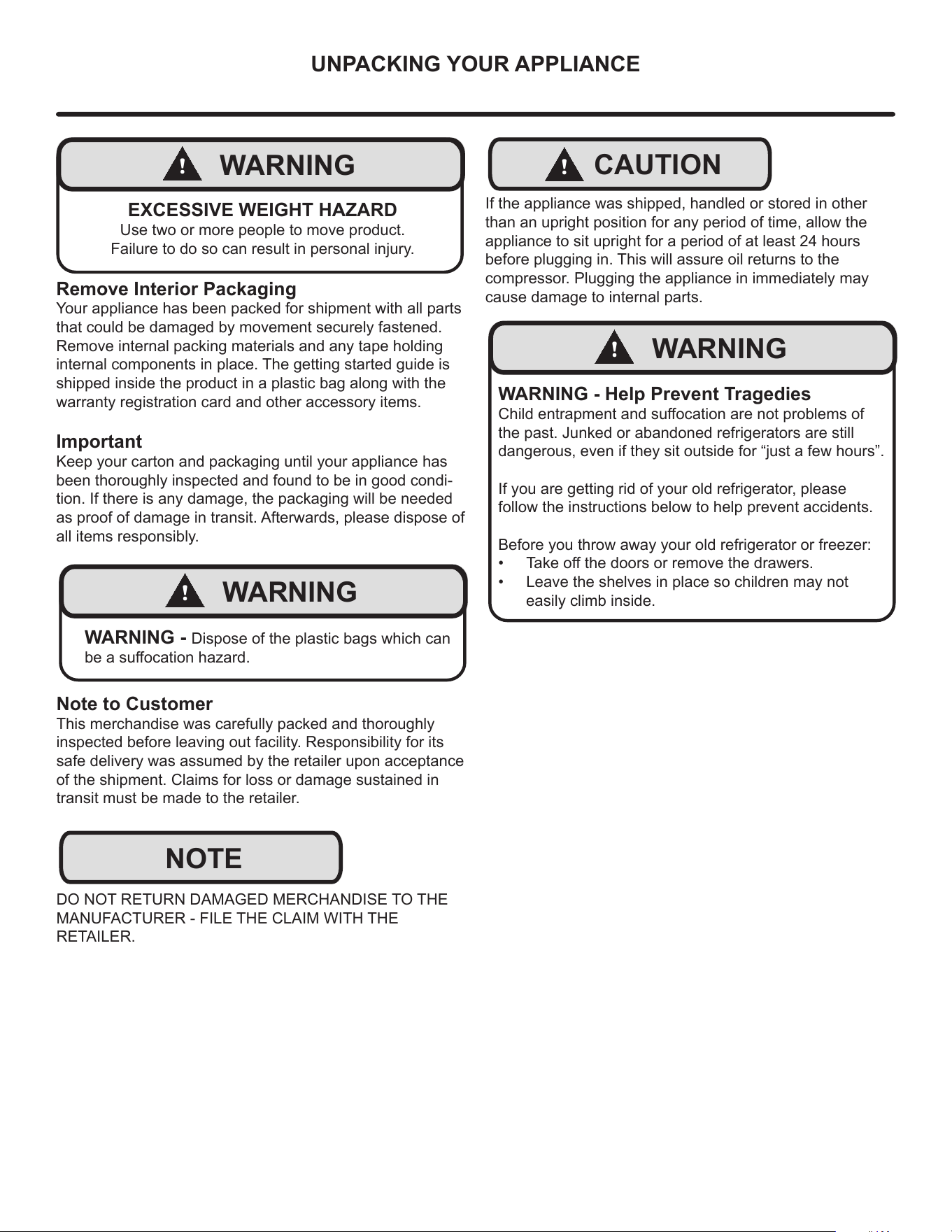
EXCESSIVE WEIGHT HAZARD
Use two or more people to move product.
Failure to do so can result in personal injury.
Remove Interior Packaging
Your appliance has been packed for shipment with all parts
that could be damaged by movement securely fastened.
Remove internal packing materials and any tape holding
internal components in place. The getting started guide is
shipped inside the product in a plastic bag along with the
warranty registration card and other accessory items.
Important
Keep your carton and packaging until your appliance has
been thoroughly inspected and found to be in good condi-
tion. If there is any damage, the packaging will be needed
as proof of damage in transit. Afterwards, please dispose of
all items responsibly.
!
WARNING
WARNING - Dispose of the plastic bags which can
be a suocation hazard.
Note to Customer
This merchandise was carefully packed and thoroughly
inspected before leaving out facility. Responsibility for its
safe delivery was assumed by the retailer upon acceptance
of the shipment. Claims for loss or damage sustained in
transit must be made to the retailer.
DO NOT RETURN DAMAGED MERCHANDISE TO THE
MANUFACTURER - FILE THE CLAIM WITH THE
RETAILER.
NOTE
!
CAUTION
If the appliance was shipped, handled or stored in other
than an upright position for any period of time, allow the
appliance to sit upright for a period of at least 24 hours
before plugging in. This will assure oil returns to the
compressor. Plugging the appliance in immediately may
cause damage to internal parts.
!
WARNING
WARNING - Help Prevent Tragedies
Child entrapment and suocation are not problems of
the past. Junked or abandoned refrigerators are still
dangerous, even if they sit outside for “just a few hours”.
If you are getting rid of your old refrigerator, please
follow the instructions below to help prevent accidents.
Before you throw away your old refrigerator or freezer:
• Take o the doors or remove the drawers.
• Leave the shelves in place so children may not
easily climb inside.
5
ELECTRICAL
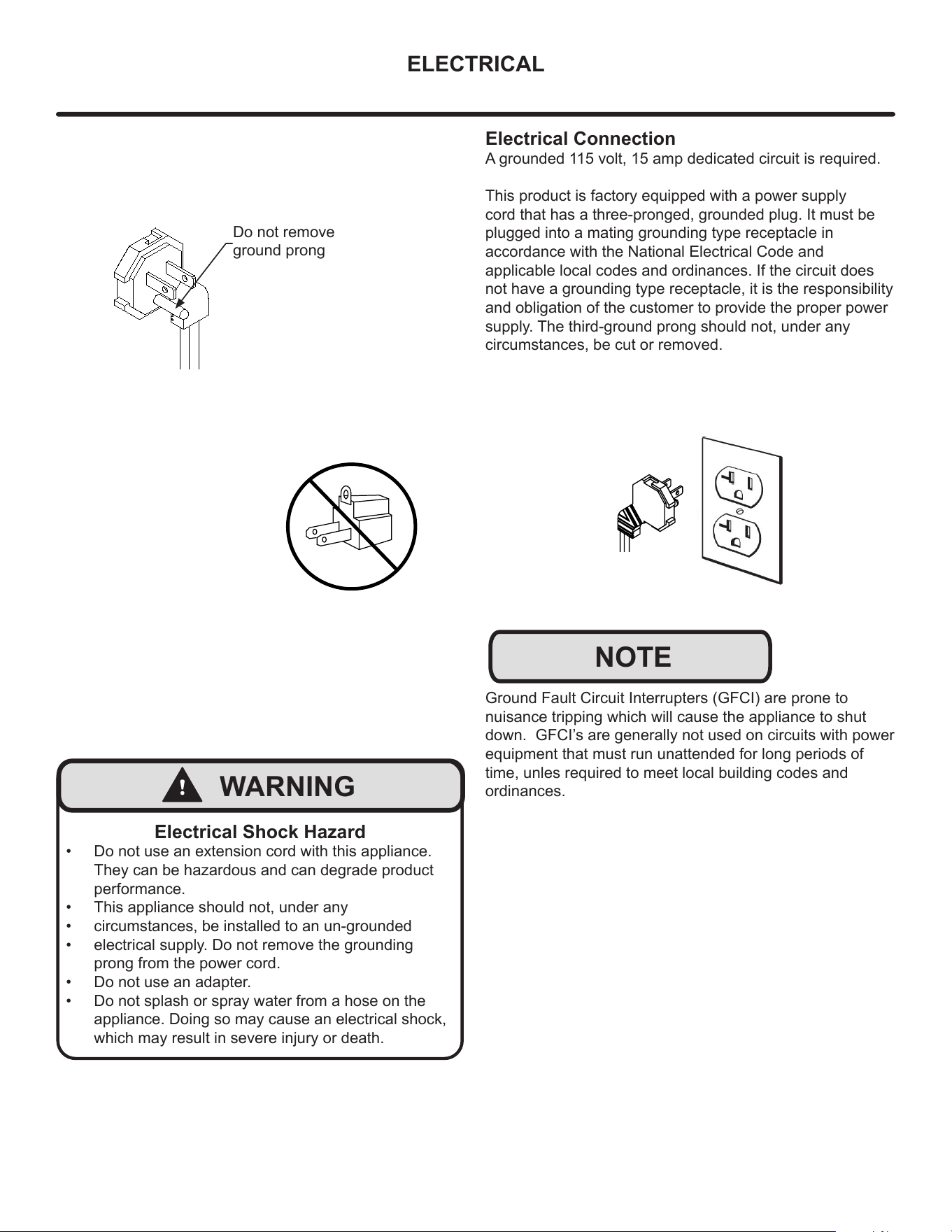
Do not remove
ground prong
!
WARNING
Electrical Shock Hazard
• Do not use an extension cord with this appliance.
They can be hazardous and can degrade product
performance.
• This appliance should not, under any
• circumstances, be installed to an un-grounded
• electrical supply. Do not remove the grounding
prong from the power cord.
• Do not use an adapter.
• Do not splash or spray water from a hose on the
appliance. Doing so may cause an electrical shock,
which may result in severe injury or death.
Electrical Connection
A grounded 115 volt, 15 amp dedicated circuit is required.
This product is factory equipped with a power supply
cord that has a three-pronged, grounded plug. It must be
plugged into a mating grounding type receptacle in
accordance with the National Electrical Code and
applicable local codes and ordinances. If the circuit does
not have a grounding type receptacle, it is the responsibility
and obligation of the customer to provide the proper power
supply. The third-ground prong should not, under any
circumstances, be cut or removed.
NOTE
Ground Fault Circuit Interrupters (GFCI) are prone to
nuisance tripping which will cause the appliance to shut
down. GFCI’s are generally not used on circuits with power
equipment that must run unattended for long periods of
time, unles required to meet local building codes and
ordinances.
6
CUTOUT AND PRODUCT DIMENSIONS
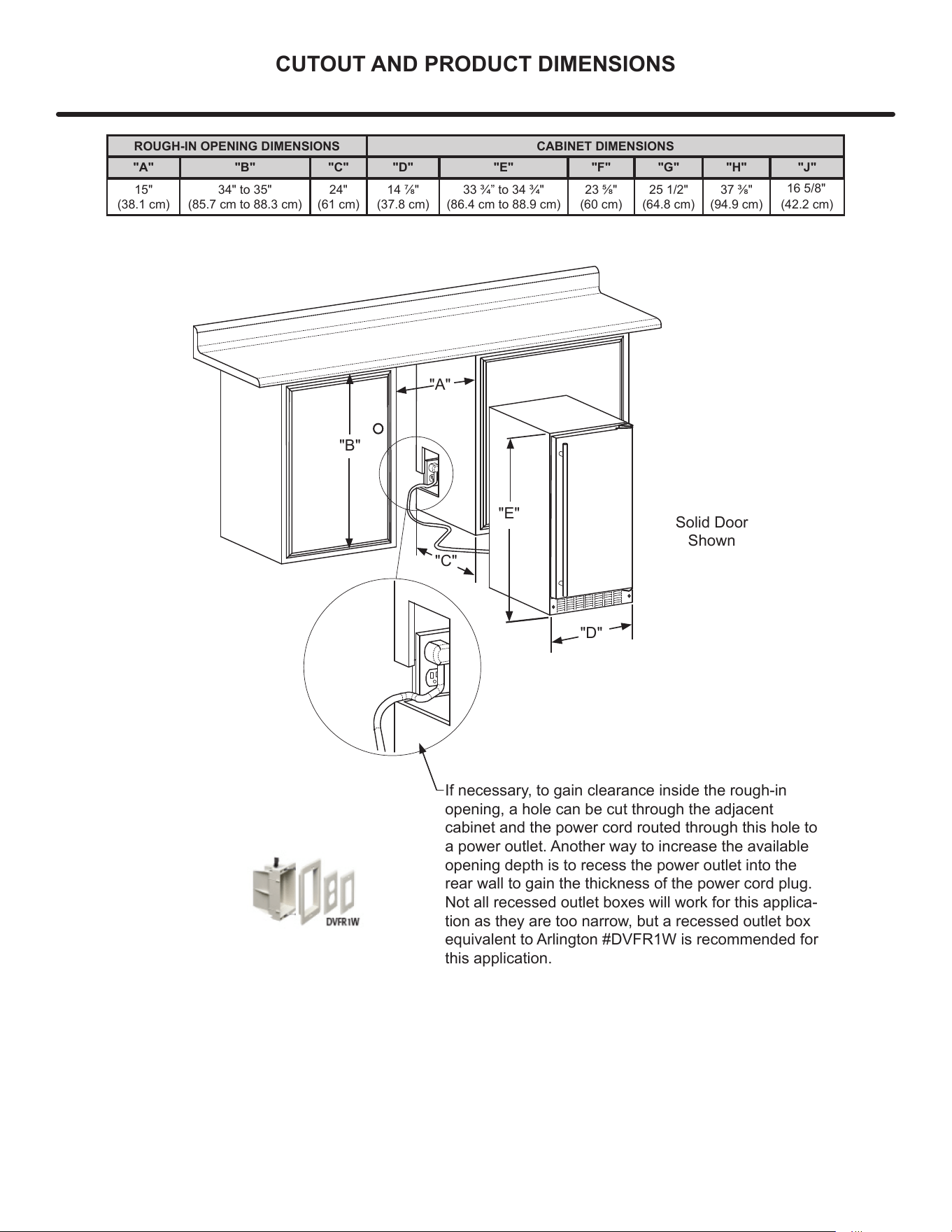
ROUGH-IN OPENING DIMENSIONS CABINET DIMENSIONS
"A" "B" "C" "D" "E" "F" "G" "H" "J"
15"
(38.1 cm)
34" to 35"
(85.7 cm to 88.3 cm)
24"
(61 cm)
14 7/8"
(37.8 cm)
33 3/4” to 34 3/4"
(86.4 cm to 88.9 cm)
23 5/8"
(60 cm)
25 1/2"
(64.8 cm)
37 3/8"
(94.9 cm)
16 5/8"
(42.2 cm)
Solid Door
Shown
"A"
"B"
"C"
"D"
"E"
If necessary, to gain clearance inside the rough-in
opening, a hole can be cut through the adjacent
cabinet and the power cord routed through this hole to
a power outlet. Another way to increase the available
opening depth is to recess the power outlet into the
rear wall to gain the thickness of the power cord plug.
Not all recessed outlet boxes will work for this applica-
tion as they are too narrow, but a recessed outlet box
equivalent to Arlington #DVFR1W is recommended for
this application.
7
CUTOUT AND PRODUCT DIMENSIONS
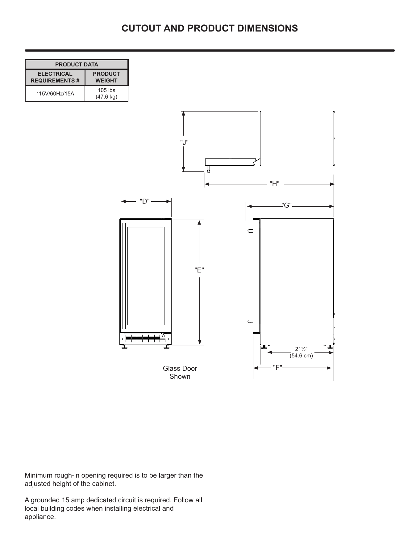
PRODUCT DATA
ELECTRICAL
REQUIREMENTS #
PRODUCT
WEIGHT
115V/60Hz/15A
105 lbs
(47.6 kg)
Minimum rough-in opening required is to be larger than the
adjusted height of the cabinet.
A grounded 15 amp dedicated circuit is required. Follow all
local building codes when installing electrical and
appliance.
Glass Door
Shown
"F"
21
1
/2"
(54.6 cm)
"D"
"E"
"H"
"J"
"G"
8
SIDE-BY-SIDE AND STACKING INSTALLATIONS
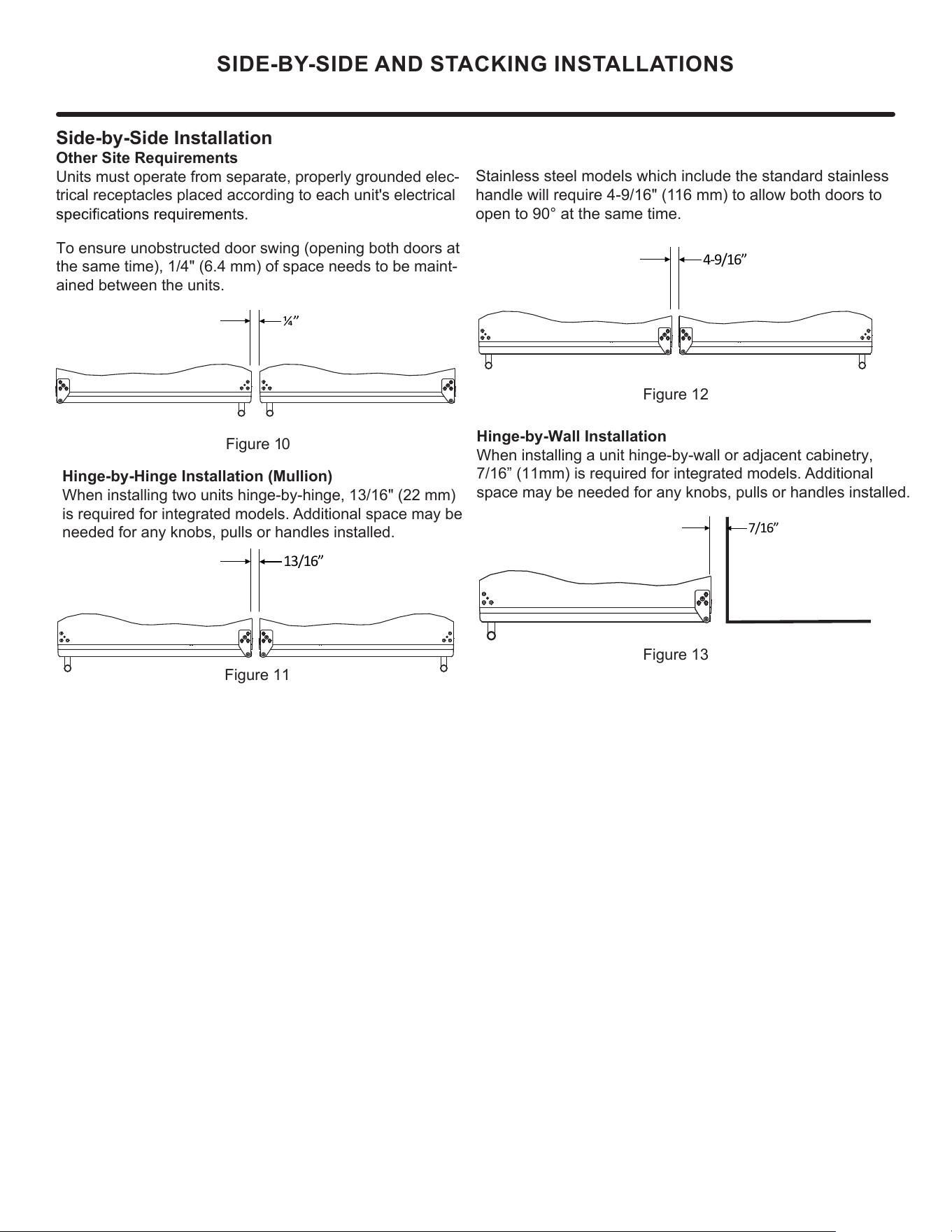
Side-by-Side Installation
Other Site Requirements
Units must operate from separate, properly grounded elec-
trical receptacles placed according to each unit's electrical
To ensure unobstructed door swing (opening both doors at
the same time), 1/4" (6.4 mm) of space needs to be maint-
ained between the units.
Hinge-by-Hinge Installation (Mullion)
When installing two units hinge-by-hinge, 13/16" (22 mm)
is required for integrated models. Additional space may be
needed for any knobs, pulls or handles installed.
Stainless steel models which include the standard stainless
handle will require 4-9/16" (116 mm) to allow both doors to
open to 90° at the same time.
Figure 10
Figure 11
Figure 12
Figure 13
Hinge-by-Wall Installation
When installing a unit hinge-by-wall or adjacent cabinetry,
7/16” (11mm) is required for integrated models. Additional
space may be needed for any knobs, pulls or handles installed.
¼”
13/16”
7/16”
4-9/16”
9
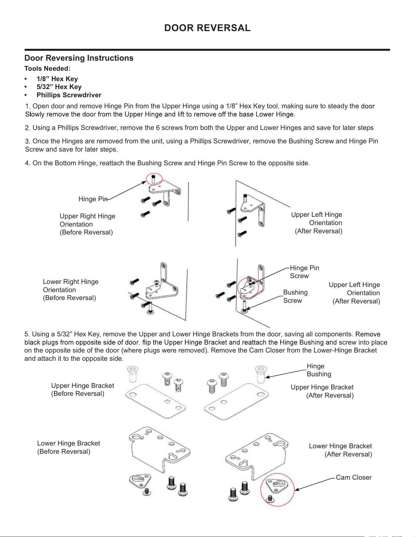
Door Reversing Instructions
Tools Needed:
• 1/8” Hex Key
• 5/32” Hex Key
• Phillips Screwdriver
Open door and remove Hinge Pin from the Upper Hinge using a 1/8” Hex Key tool making sure to steady the
Using a Phillips Screwdriver, remove the 6 screws from both the Upper and Lower Hinges and save for later steps
Once the Hinges are removed from the unit, using a Phillips Screwdriver, remove the Bushing Screw and Hinge Pin
Screw and save for later steps
On the Bottom Hinge, reattach the Bushing Screw and Hinge Pin Screw to the opposite side
Lower Hinge Bracket
(Before Reversal)
Upper Hinge Bracket
(After Reversal)
Lower Hinge Bracket
(After Reversal)
5. Using a 5/32” Hex Key, remove the Upper and Lower Hinge Brackets from the door saving all components.
screw into place
on the opposite side of the door (where plugs were removed). Remove the Cam Closer from the Lower-Hinge Bracket
and attach it to the opposite side
DOOR REVERSAL
Hinge Pin
Upper Right Hinge
Orientation
(Before Reversal)
Hinge Pin
Screw
Bushing
Screw
Lower Right Hinge
Orientation
(Before Reversal)
pper Left Hinge
Orientation
(After Reversal)
Upper Left Hinge
Orientation
(After Reversal)
Hinge
Bushing
Cam Closer
Upper Hinge Bracket
(Before Reversal)
10
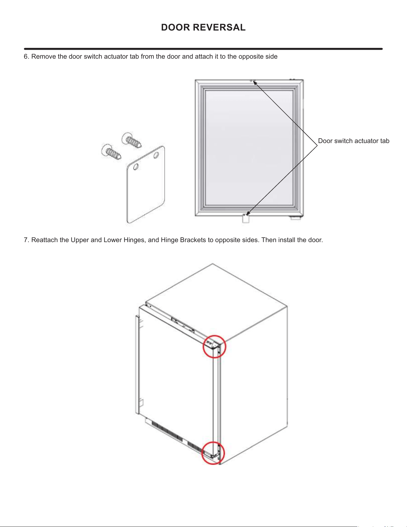
6. Remove the door switch actuator tab from the door and attach it to the opposite side
DOOR REVERSAL
Door switch actuator tab
7. Reattach the Upper and Lower Hinges, and Hinge Brackets to opposite sides. Then install the door.
11
USING YOUR ELECTRONIC CONTROLS
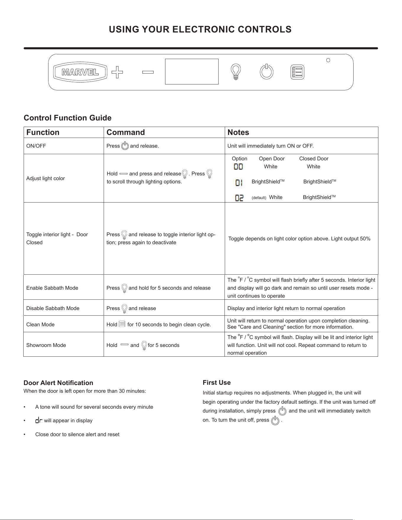
Control Function Guide
Function Command Notes
ON/OFF Press and release. Unit will immediately turn ON or OFF.
Adjust light color
Option Open Door Closed Door
White White
Toggle interior light - Door
Closed
Press and release to toggle interior light op-
tion; press again to deactivate
Toggle depends on light color option above./LJKWRXWSXW
Enable Sabbath Mode Press and hold for 5 seconds and release
The
o
F /
o
C symbol will flash briefly after 5 seconds. Interior light
and display will go dark and remain so until user resets mode -
unit continues to operate
Disable Sabbath Mode Press and release Display and interior light return to normal operation
Clean Mode
Hold for 10 seconds to begin clean cycle.
Showroom Mode Hold and for 5 seconds
The
º
F /
º
C symbol will flash. Display will be lit and interior light
will function. Unit will not cool. Repeat command to return to
normal operation
Door Alert Notification
When the door is left open for more than 30 minutes:
• A tone will sound for several seconds every minute
• will appear in display
• Close door to silence alert and reset
Hold and press and release . Press
to scroll through lighting options.
BrightShield
TM
BrightShield
TM
(default) White BrightShield
TM
Unit will return to normal operation upon completion cleaning.
See "Care and Cleaning" section for more information.
First Use
Initial startup requires no adjustments. When plugged in, the unit will
begin operating under the factory default settings. If the unit was turned off
during installation, simply press and the unit will immediately switch
on. To turn the unit off, press
.
12

BrightShield™
7KLVPRGHOLQFOXGHV%ULJKW6KLHOGZLWK9\Y$QWLPLFURELDO/LJKW7HFKQRORJ\
%ULJKW6KLHOG
.LOOVDQGSUHYHQWVWKHJURZWKRIYLUXVHVEDFWHULDIXQJL\HDVWVPROGDQGPLOGHZ
3URYLGHVFRQWLQXRXVDQWLPLFURELDODFWLRQWRNHHSVXUIDFHVFOHDQ
,VDSSURYHGIRUFRQWLQXRXVXVHDURXQGSHRSOHSHWVSODQWV
5HGXFHVRGRUVFDXVHGE\EDFWHULDIXQJL\HDVWVPROGDQGPLOGHZ
&UHDWHVDFOHDQHUHQYLURQPHQWIRUIRRGEHYHUDJHVLFH
%ULJKW6KLHOGLVPRVWHIIHFWLYHZKHQXVHGFRQWLQXRXVO\<RXUXQLWLVIDFWRU\VHWWRXVH%ULJKW6KLHOGOLJKWLQJZKHQHYHU
WKHGRRULVFORVHGDQGVWDQGDUGEULJKWZKLWHZKHQWKHGRRULVRSHQ6HH&RQWURO2SHUDWLRQVVHFWLRQVIRUGHWDLOVDQGRWKHU
RSWLRQV
)RUPRUHLQIRUPDWLRQDERXW%ULJKW6KLHOGYLVLWZZZPDUYHOUHIULJHUDWLRQFRP
)RUPRUHLQIRUPDWLRQDERXW9\Y$QWLPLFURELDO/LJKW7HFKQRORJ\YLVLWZZZY\YWHFK
7HVWLQJRQDQRQHQYHORSHGYLUXV06EDFWHULRSKDJHVKRZHGDUHGXFWLRQLQFRQWUROOHGODERUDWRU\WHVWLQJLQ
KRXUVRQKDUGVXUIDFHV7HVWLQJRQ6$56&R9HQYHORSHGYLUXVVKRZHGDUHGXFWLRQLQFRQWUROOHGODERUDWRU\
WHVWLQJLQKRXUVRQKDUGVXUIDFHV7HVWLQJRQ056$(FROLVKRZHGUHGXFWLRQLQFRQWUROOHGODERUDWRU\WHVWLQJLQ
KRXUVRQKDUGVXUIDFHV5HVXOWVPD\YDU\GHSHQGLQJRQWKHDPRXQWRIOLJKWWKDWLVUHDFKLQJWKHVXUIDFHVLQWKHVSDFH
USING YOUR
ELECTRONIC CONTROLS
13
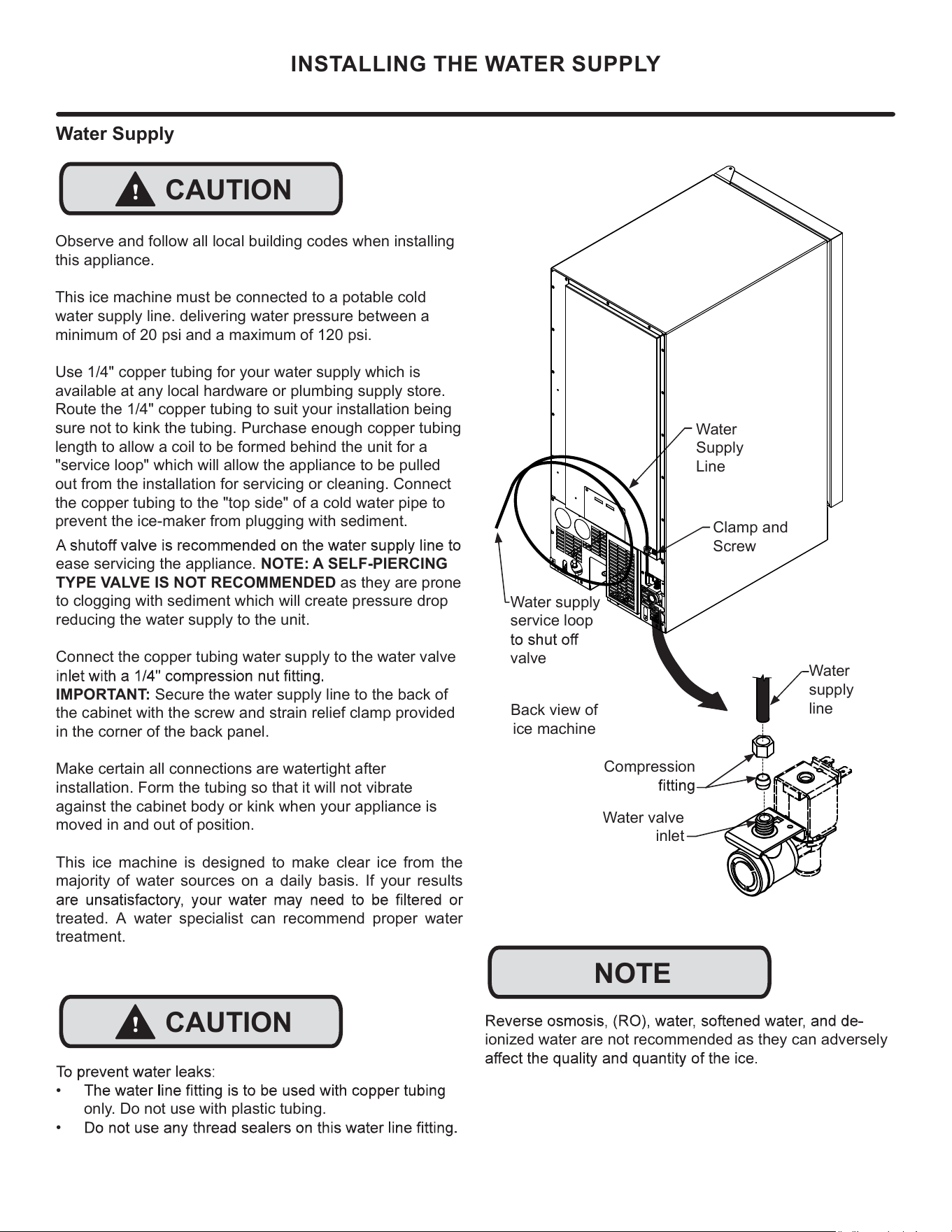
ionized water are not recommended as they can adversely
Water
Supply
Line
Clamp and
Screw
Back view of
ice machine
NOTE
!
CAUTION
INSTALLING THE WATER SUPPLY
Compression
Water
supply
line
Water supply
service loop
valve
Water valve
inlet
Water Supply
Observe and follow all local building codes when installing
this appliance.
This ice machine must be connected to a potable cold
water supply line. delivering water pressure between a
minimum of 20 psi and a maximum of 120 psi.
Use 1/4" copper tubing for your water supply which is
available at any local hardware or plumbing supply store.
Route the 1/4" copper tubing to suit your installation being
sure not to kink the tubing. Purchase enough copper tubing
length to allow a coil to be formed behind the unit for a
"service loop" which will allow the appliance to be pulled
out from the installation for servicing or cleaning. Connect
the copper tubing to the "top side" of a cold water pipe to
prevent the ice-maker from plugging with sediment.
ease servicing the appliance. NOTE: A SELF-PIERCING
TYPE VALVE IS NOT RECOMMENDED as they are prone
to clogging with sediment which will create pressure drop
reducing the water supply to the unit.
Connect the copper tubing water supply to the water valve
IMPORTANT: Secure the water supply line to the back of
the cabinet with the screw and strain relief clamp provided
in the corner of the back panel.
Make certain all connections are watertight after
installation. Form the tubing so that it will not vibrate
against the cabinet body or kink when your appliance is
moved in and out of position.
This ice machine is designed to make clear ice from the
majority of water sources on a daily basis. If your results
treated. A water specialist can recommend proper water
treatment.
!
CAUTION
•
only. Do not use with plastic tubing.
•
14
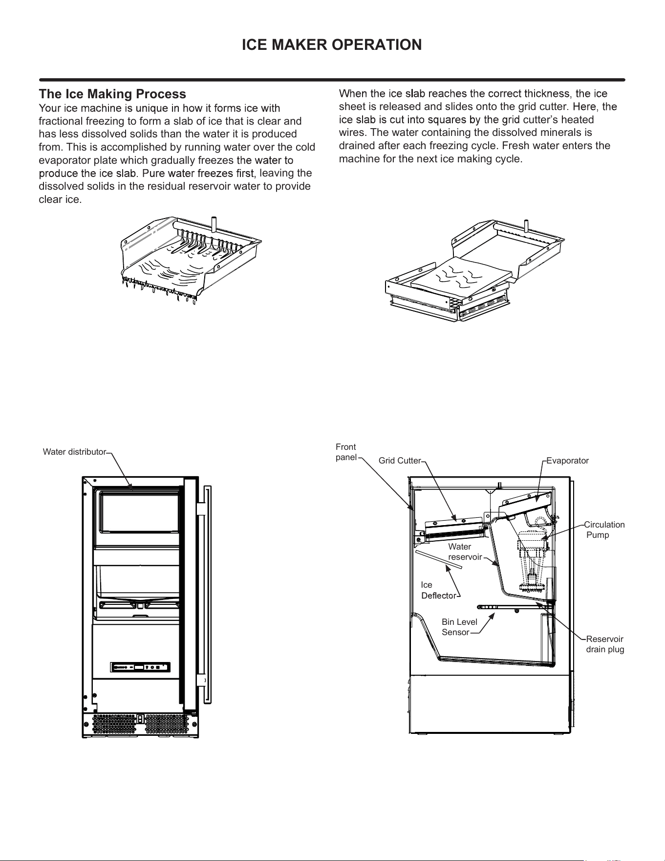
The Ice Making Process
fractional freezing to form a slab of ice that is clear and
has less dissolved solids than the water it is produced
from. This is accomplished by running water over the cold
evaporator plate which gradually freezes
leaving the
dissolved solids in the residual reservoir water to provide
clear ice.
sheet is released and slides onto the grid cutter
cutter’s heated
wires. The water containing the dissolved minerals is
drained after each freezing cycle. Fresh water enters the
machine for the next ice making cycle.
Water distributor
Water
reservoir
Evaporator
Circulation
Pump
Reservoir
drain plug
Front
panel
Bin Level
Sensor
Ice
Grid Cutter
ICE MAKER OPERATION
15
when the ice supply is low or full and starts or stops the ice
making process accordingly.
power to the unit.
New Sounds
your household refrigerator. Because these sounds are
new to you they may be of a concern but are most likely
normal. The ice production process will make noises that
valves opening and closing. Following are some of the
A buzzing sound will be heard when the water valve
water line.
evaporator plate and into the water reservoir.
A "thud" when the ice slab is released from the
evaporator plate and slides onto the grid cutter.
"Clicks" when the cubes fall into the ice storage bin.
machine.
An air noise from the condenser fan.
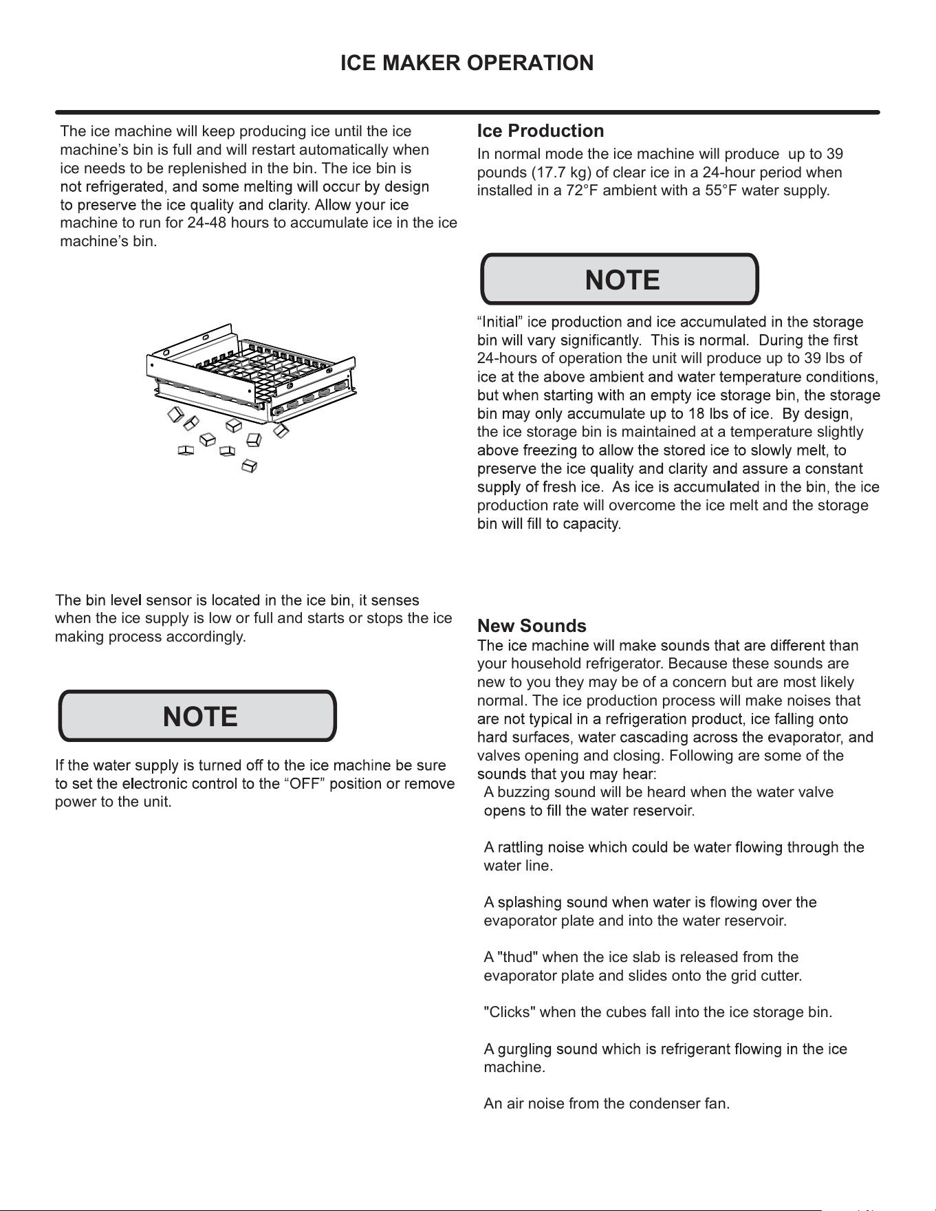
Ice Production
In normal mode the ice machine will produce up to 39
pounds (17.7 kg) of clear ice in a 24-hour period when
installed in a 72°F ambient with a 55°F water supply.
24-hours of operation the unit will produce up to 39 lbs of
the ice storage bin is maintained at a temperature slightly
production rate will overcome the ice melt and the storage
NOTE
NOTE
The ice machine will keep producing ice until the ice
machine’s bin is full and will restart automatically when
ice needs to be replenished in the bin. The ice bin is
machine to run for 24-48 hours to accumulate ice in the ice
machine’s bin.
ICE MAKER OPERATION
16
!
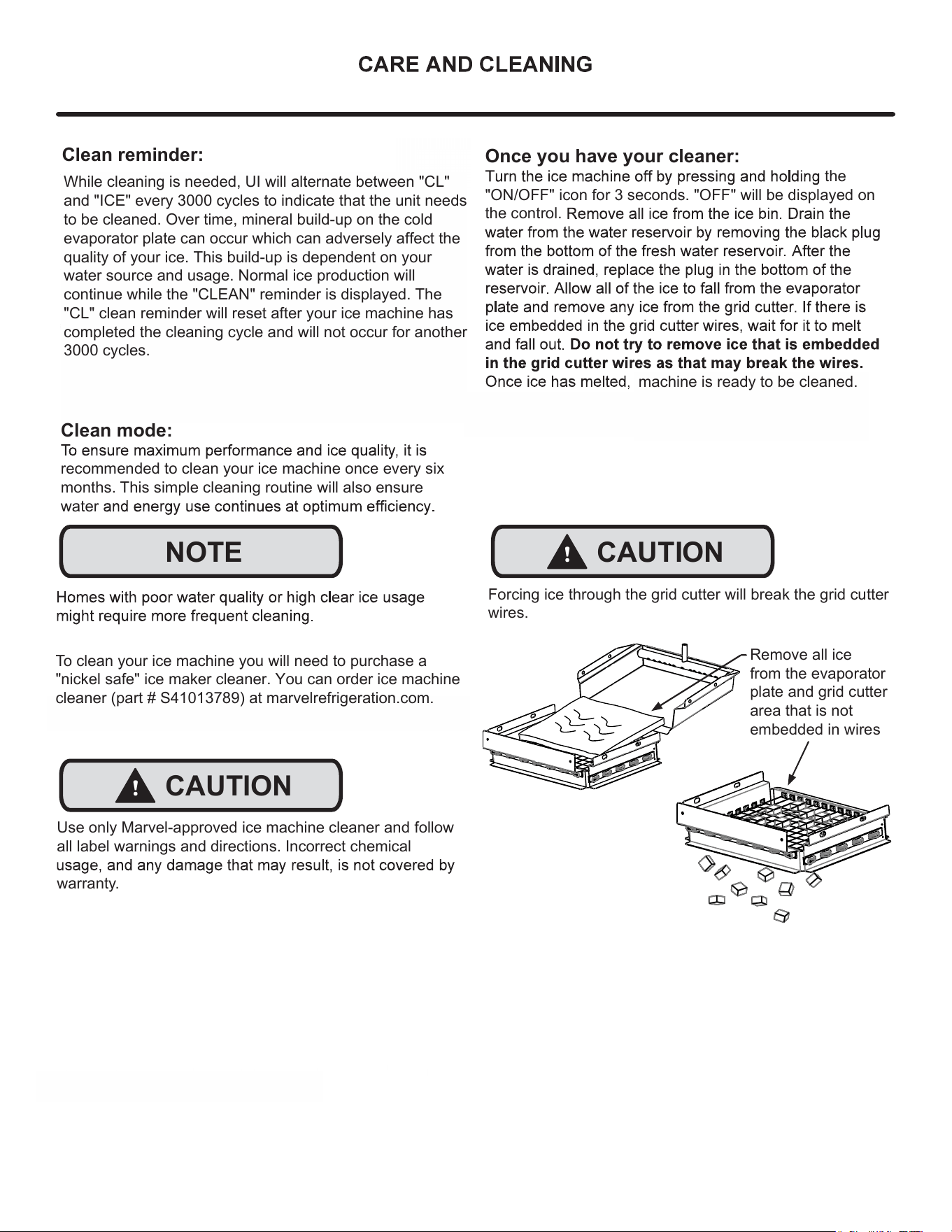
CAUTION
Forcing ice through the grid cutter will break the grid cutter
wires.
!
CAUTION
Remove all ice
from the evaporator
plate and grid cutter
area that is not
embedded in wires
Clean reminder:
CLEAN
NOTE
OFF
dependent on
your water source and usage. Normal ice production will
continue while the "CLEAN" reminder is displayed.
When
another
. If you choose to clean the appliance at
Clean mode:
recommended to clean your ice machine once every six
months. This simple cleaning routine will also ensure
water
Once you have your cleaner:
the
"ON/OFF" icon for 3 seconds. "OFF" will be displayed on
the control.
Use only Marvel-approved ice machine cleaner and follow
all label warnings and directions. Incorrect chemical
warranty.
To clean your ice machine you will need to purchase a
"nickel safe" ice maker cleaner. You can order ice machine
cleaner (part # S41013789) at marvelrefrigeration.com.
machine is ready to be cleaned.
While cleaning is needed, UI will alternate between "CL"
and "ICE" every 3000 cycles to indicate that the unit needs
to be cleaned. Over time, mineral build-up on the cold
evaporator plate can occur which can adversely affect the
quality of your ice. This build-up is dependent on your
water source and usage. Normal ice production will
continue while the "CLEAN" reminder is displayed. The
"CL" clean reminder will reset after your ice machine has
completed the cleaning cycle and will not occur for another
3000 cycles.
17
CARE AND CLEANING
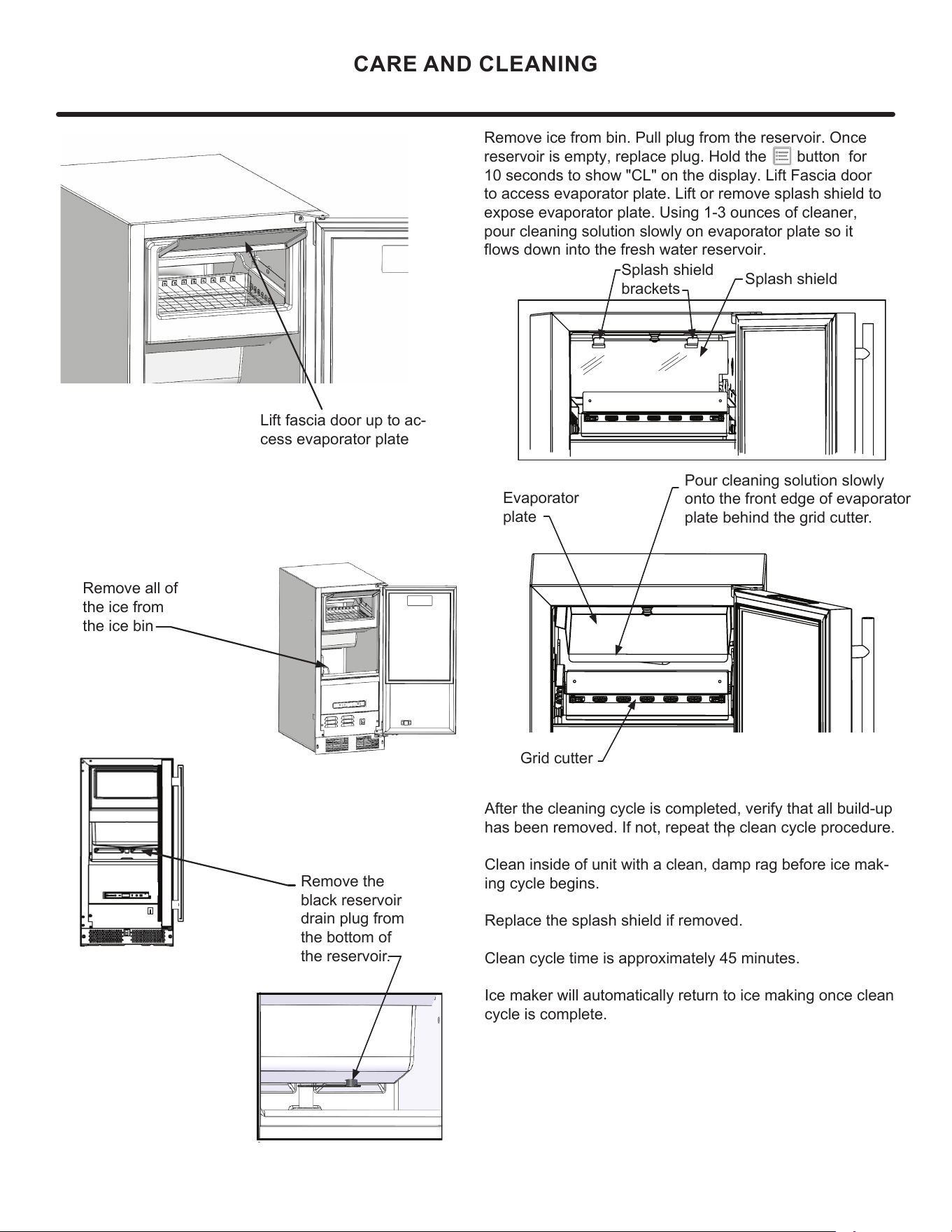
Remove all of
the ice from
the ice bin
Remove the
black reservoir
drain plug from
the bottom of
the reservoir.
Splash shield
brackets
After the cleaning cycle is completed, verify that all build-up
has been removed. If not, repeat the clean cycle procedure.
Clean inside of unit with a clean, damp rag before ice mak-
ing cycle begins.
Replace the splash shield if removed.
Clean cycle time is approximately 45 minutes.
Ice maker will automatically return to ice making once clean
cycle is complete.
Pour cleaning solution slowly
onto the front edge of evaporator
plate behind the grid cutter.
Evaporator
plate
Grid cutter
Splash shield
Lift fascia door up to ac-
cess evaporator plate
Remove ice from bin. Pull plug from the reservoir. Once
reservoir is empty, replace plug. Hold the button for
10 seconds to show "CL" on the display. Lift Fascia door
to access evaporator plate. Lift or remove splash shield to
expose evaporator plate. Using 1-3 ounces of cleaner,
pour cleaning solution slowly on evaporator plate so it
flows down into the fresh water reservoir.
18
19
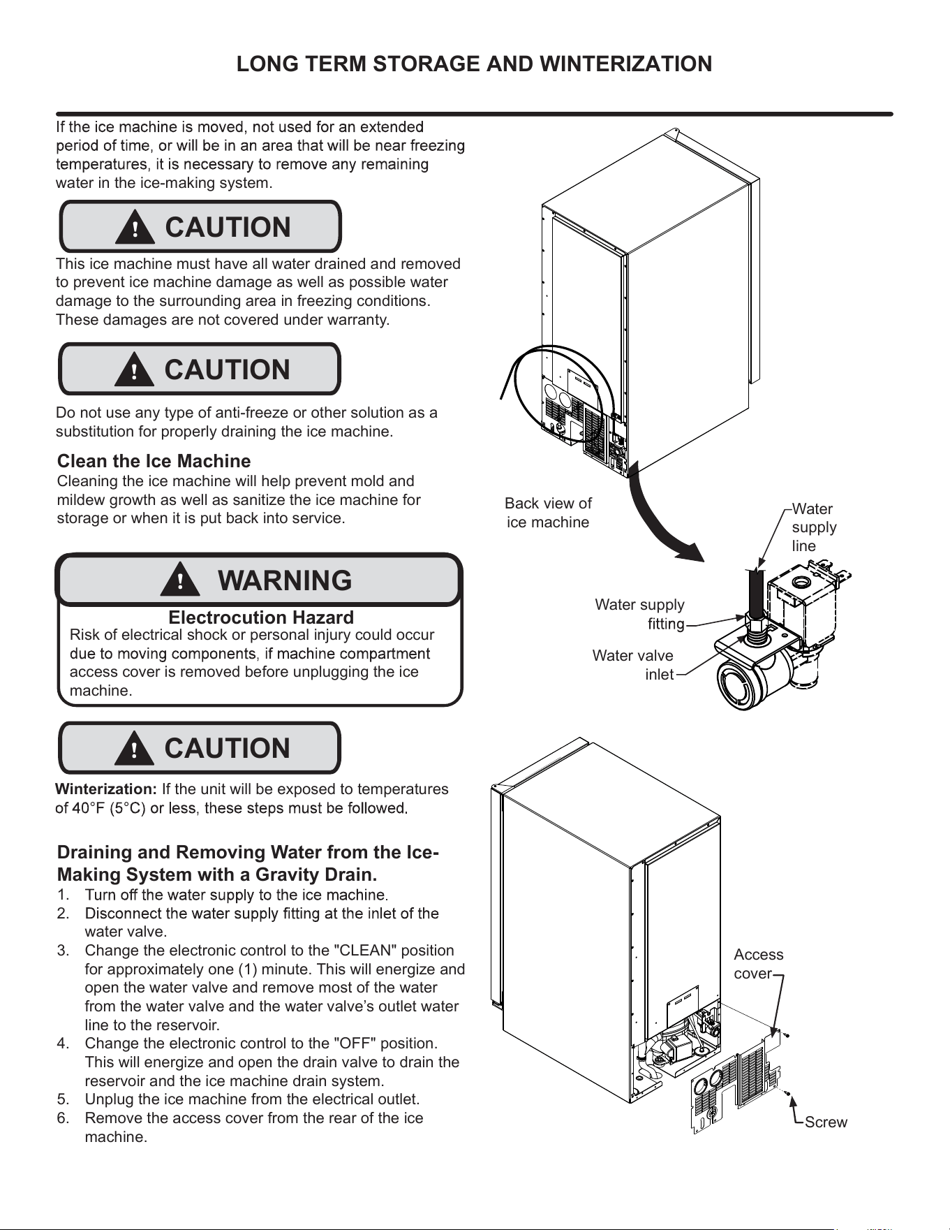
Draining and Removing Water from the Ice-
Making System with a Gravity Drain.
1.
2.
3.
water valve.
Change the electronic control to the "CLEAN" position
for approximately one (1) minute. This will energize and
open the water valve and remove most of the water
from the water valve and the water valve’s outlet water
line to the reservoir.
4. Change the electronic control to the "OFF" position.
This will energize and open the drain valve to drain the
reservoir and the ice machine drain system.
5. Unplug the ice machine from the electrical outlet.
6. Remove the access cover from the rear of the ice
machine.
water in the ice-making system.
This ice machine must have all water drained and removed
to prevent ice machine damage as well as possible water
damage to the surrounding area in freezing conditions.
These damages are not covered under warranty.
Do not use any type of anti-freeze or other solution as a
substitution for properly draining the ice machine.
Clean the Ice Machine
Cleaning the ice machine will help prevent mold and
mildew growth as well as sanitize the ice machine for
storage or when it is put back into service.
!
CAUTION
!
CAUTION
Risk of electrical shock or personal injury could occur
access cover is removed before unplugging the ice
machine.
!
WARNING
Electrocution Hazard
Back view of
ice machine
Water supply
Water
supply
line
Water valve
inlet
Access
cover
Screw
!
CAUTION
Winterization: If the unit will be exposed to temperatures
LONG TERM STORAGE AND WINTERIZATION
20
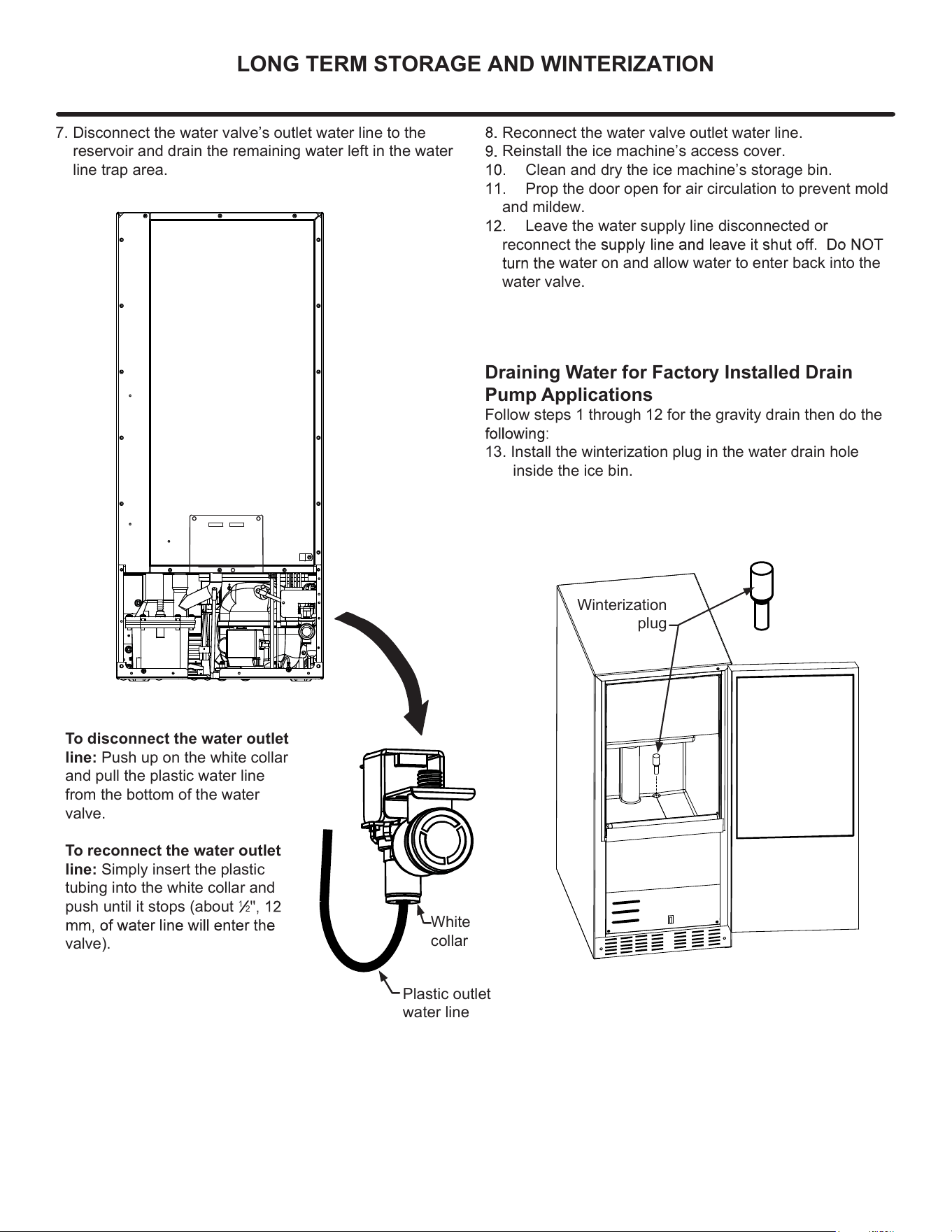
Reconnect the water valve outlet water line.
Reinstall the ice machine’s access cover.
Clean and dry the ice machine’s storage bin.
Prop the door open for air circulation to prevent mold
and mildew.
Leave the water supply line disconnected or
reconnect
water on and allow water to enter back into the
water valve.
White
collar
Plastic outlet
water line
7. Disconnect the water valve’s outlet water line to the
reservoir and drain the remaining water left in the water
line trap area.
To disconnect the water outlet
line: Push up on the white collar
and pull the plastic water line
from the bottom of the water
valve.
To reconnect the water outlet
line: Simply insert the plastic
tubing into the white collar and
push until it stops (about
1
2
valve).
Draining Water for Factory Installed Drain
Pump Applications
Follow steps 1 through 12 for the gravity drain then do the
13. Install the winterization plug in the water drain hole
inside the ice bin.
Winterization
plug
LONG TERM STORAGE AND WINTERIZATION
21
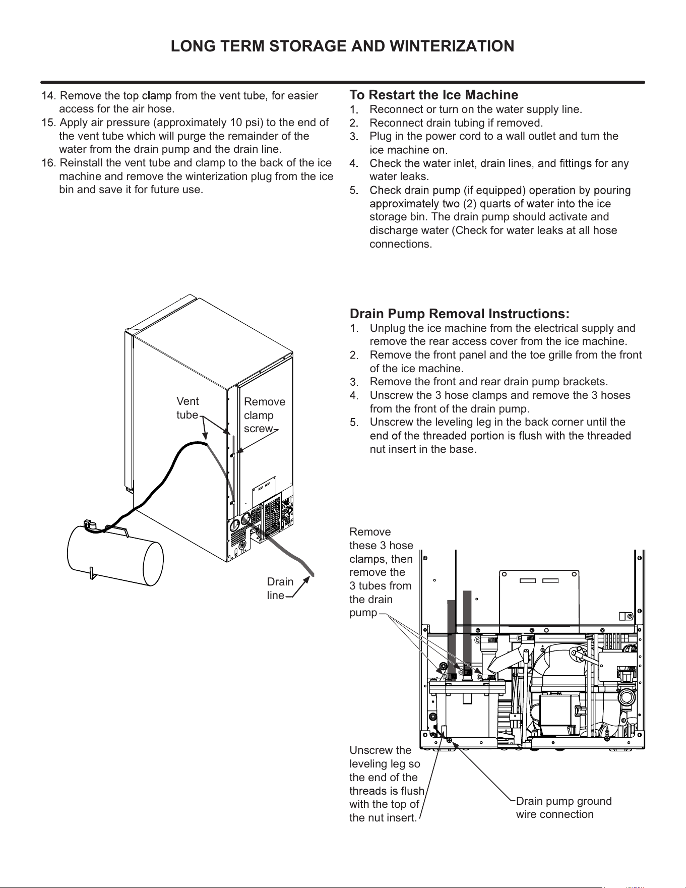
Drain Pump Removal Instructions:
Unplug the ice machine from the electrical supply and
remove the rear access cover from the ice machine.
Remove the front panel and the toe grille from the front
of the ice machine.
Remove the front and rear drain pump brackets.
Unscrew the 3 hose clamps and remove the 3 hoses
from the front of the drain pump.
Unscrew the leveling leg in the back corner until the
nut insert in the base.
To Restart the Ice Machine
Reconnect or turn on the water supply line.
Reconnect drain tubing if removed.
Plug in the power cord to a wall outlet and turn the
water leaks.
storage bin. The drain pump should activate and
discharge water (Check for water leaks at all hose
connections.
access for the air hose.
Apply air pressure (approximately 10 psi) to the end of
the vent tube which will purge the remainder of the
water from the drain pump and the drain line.
Reinstall the vent tube and clamp to the back of the ice
machine and remove the winterization plug from the ice
bin and save it for future use.
Vent
tube
Remove
clamp
screw
Drain
line
LONG TERM STORAGE AND WINTERIZATION
Unscrew the
leveling leg so
the end of the
with the top of
the nut insert.
Remove
these 3 hose
remove the
3 tubes from
the drain
pump
Drain pump ground
wire connection
22
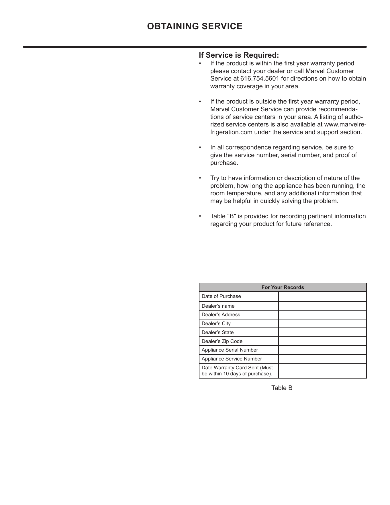
If Service is Required:
• If the product is within the rst year warranty period
please contact your dealer or call Marvel Customer
Service at 616.754.5601 for directions on how to obtain
warranty coverage in your area.
• If the product is outside the rst year warranty period,
Marvel Customer Service can provide recommenda-
tions of service centers in your area. A listing of autho-
rized service centers is also available at www.marvelre-
frigeration.com under the service and support section.
• In all correspondence regarding service, be sure to
give the service number, serial number, and proof of
purchase.
• Try to have information or description of nature of the
problem, how long the appliance has been running, the
room temperature, and any additional information that
may be helpful in quickly solving the problem.
• Table "B" is provided for recording pertinent information
regarding your product for future reference.
For Your Records
Date of Purchase
Dealer’s name
Dealer’s Address
Dealer’s City
Dealer’s State
Dealer’s Zip Code
Appliance Serial Number
Appliance Service Number
Date Warranty Card Sent (Must
be within 10 days of purchase).
Table B
OBTAINING SERVICE
23
• Never attempt to repair or perform maintenance on
the appliance until the main electrical power has been
disconnected. Turning the appliance control "OFF"
does not remove electrical power from the unit's wiring.
• Replace all parts and panels before operating.
!
WARNING
Electrocution Hazard
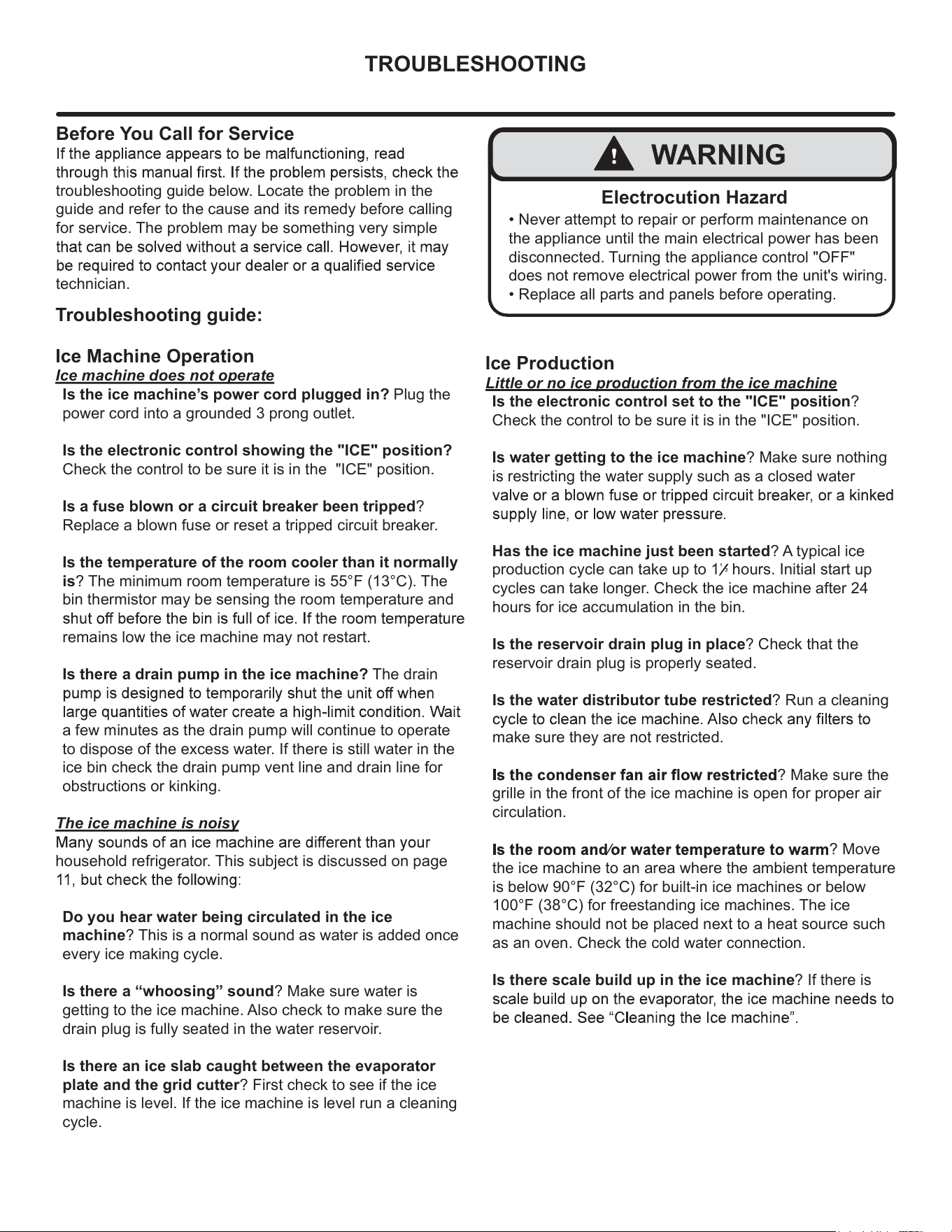
TROUBLESHOOTING
Before You Call for Service
troubleshooting guide below. Locate the problem in the
guide and refer to the cause and its remedy before calling
for service. The problem may be something very simple
technician.
Troubleshooting guide:
Ice Machine Operation
Ice machine does not operate
Is the ice machine’s power cord plugged in? Plug the
power cord into a grounded 3 prong outlet.
Is the electronic control showing the "ICE" position?
Check the control to be sure it is in the "ICE" position.
Is a fuse blown or a circuit breaker been tripped?
Replace a blown fuse or reset a tripped circuit breaker.
Is the temperature of the room cooler than it normally
is? The minimum room temperature is 55°F (13°C). The
bin thermistor may be sensing the room temperature and
remains low the ice machine may not restart.
Is there a drain pump in the ice machine? The drain
a few minutes as the drain pump will continue to operate
to dispose of the excess water. If there is still water in the
ice bin check the drain pump vent line and drain line for
obstructions or kinking.
The ice machine is noisy
household refrigerator. This subject is discussed on page
Do you hear water being circulated in the ice
machine? This is a normal sound as water is added once
every ice making cycle.
Is there a “whoosing” sound? Make sure water is
getting to the ice machine. Also check to make sure the
drain plug is fully seated in the water reservoir.
Is there an ice slab caught between the evaporator
plate and the grid cutter? First check to see if the ice
machine is level. If the ice machine is level run a cleaning
cycle.
Ice Production
Little or no ice production from the ice machine
Is the electronic control set to the "ICE" position?
Check the control to be sure it is in the "ICE" position.
Is water getting to the ice machine? Make sure nothing
is restricting the water supply such as a closed water
Has the ice machine just been started? A typical ice
production cycle can take up to 1
¹
²
hours. Initial start up
cycles can take longer. Check the ice machine after 24
hours for ice accumulation in the bin.
Is the reservoir drain plug in place? Check that the
reservoir drain plug is properly seated.
Is the water distributor tube restricted? Run a cleaning
make sure they are not restricted.
? Make sure the
grille in the front of the ice machine is open for proper air
circulation.
? Move
the ice machine to an area where the ambient temperature
is below 90°F (32°C) for built-in ice machines or below
100°F (38°C) for freestanding ice machines. The ice
machine should not be placed next to a heat source such
as an oven. Check the cold water connection.
Is there scale build up in the ice machine? If there is
24
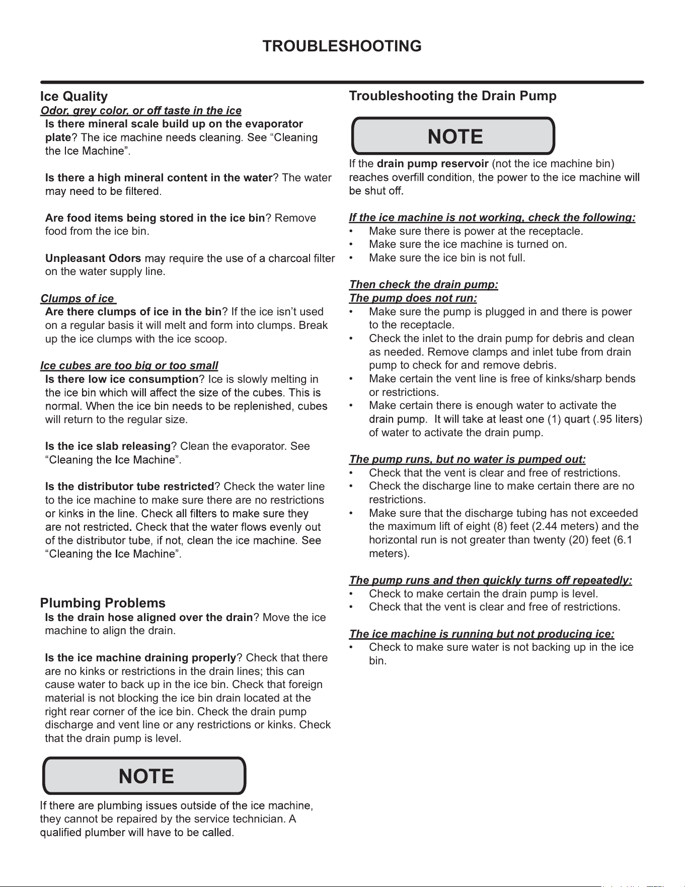
TROUBLESHOOTING
Plumbing Problems
Is the drain hose aligned over the drain? Move the ice
machine to align the drain.
Is the ice machine draining properly? Check that there
are no kinks or restrictions in the drain lines; this can
cause water to back up in the ice bin. Check that foreign
material is not blocking the ice bin drain located at the
right rear corner of the ice bin. Check the drain pump
discharge and vent line or any restrictions or kinks. Check
that the drain pump is level.
they cannot be repaired by the service technician. A
Ice Quality
Is there mineral scale build up on the evaporator
plate
Is there a high mineral content in the water? The water
Are food items being stored in the ice bin? Remove
food from the ice bin.
Unpleasant Odors
on the water supply line.
Clumps of ice
Are there clumps of ice in the bin? If the ice isn’t used
on a regular basis it will melt and form into clumps. Break
up the ice clumps with the ice scoop.
Ice cubes are too big or too small
Is there low ice consumption? Ice is slowly melting in
will return to the regular size.
Is the ice slab releasing? Clean the evaporator. See
Is the distributor tube restricted? Check the water line
to the ice machine to make sure there are no restrictions
Troubleshooting the Drain Pump
If the drain pump reservoir (not the ice machine bin)
If the ice machine is not working, check the following:
• Make sure there is power at the receptacle.
• Make sure the ice machine is turned on.
• Make sure the ice bin is not full.
Then check the drain pump:
The pump does not run:
• Make sure the pump is plugged in and there is power
to the receptacle.
• Check the inlet to the drain pump for debris and clean
as needed. Remove clamps and inlet tube from drain
pump to check for and remove debris.
• Make certain the vent line is free of kinks/sharp bends
or restrictions.
• Make certain there is enough water to activate the
of water to activate the drain pump.
The pump runs, but no water is pumped out:
• Check that the vent is clear and free of restrictions.
• Check the discharge line to make certain there are no
restrictions.
• Make sure that the discharge tubing has not exceeded
the maximum lift of eight (8) feet (2.44 meters) and the
horizontal run is not greater than twenty (20) feet (6.1
meters).
• Check to make certain the drain pump is level.
• Check that the vent is clear and free of restrictions.
The ice machine is running but not producing ice:
• Check to make sure water is not backing up in the ice
bin.
NOTE
NOTE
25
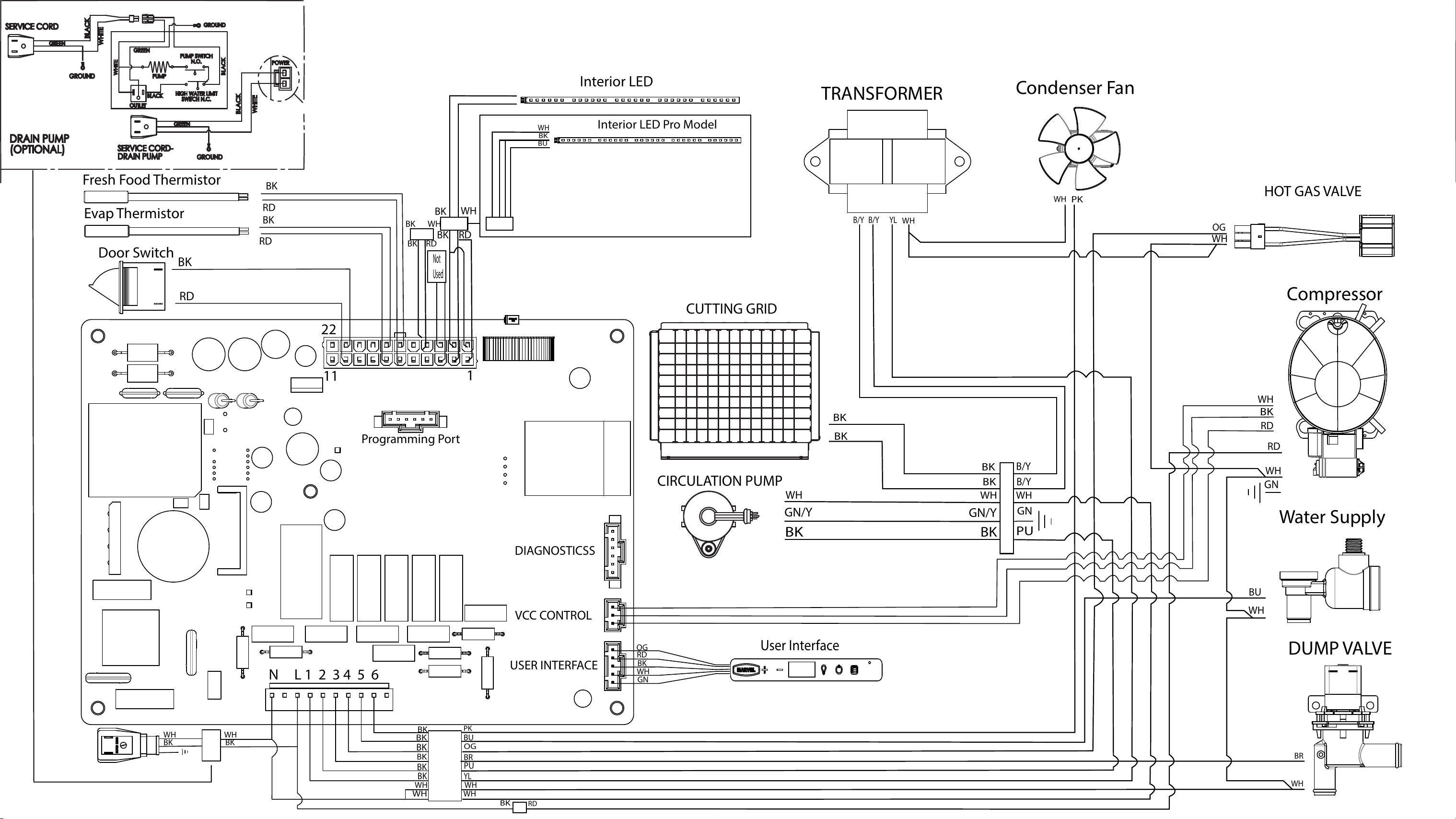
Condenser Fan
User Interface
Door Switch
Water Supply
Evap Thermistor
Fresh Food Thermistor
BK
WH
RD
BK
BK
RD
BK
RD
RD
BK
WH WH
BK
BK
BK
BK
BK
BK
BK
BK
WH
WH
WH
BU
PU
PK
BR
Programming Port
DIAGNOSTICSS
USER INTERFACE
VCC CONTROL
Interior LED
OG
RD
BK
WH
GN
WH
Not
Used
BK
WH
RD
BK
Interior LED Pro Model
BK
WH
BU
BK
RD
WH
Compressor
GN
RD
OG
OG
YL
WH
CUTTING GRID
CIRCULATION PUMP
HOT GAS VALVE
TRANSFORMER
DUMP VALVE
BU
PK
BR
PU
YL
WH
WH
GN
B/Y B/Y
B/Y
B/Y
WH
WH
WH
BK
GN/Y
BK
BK
BK
BK
WH
WH
GN/Y
BK
WHITE
GREEN
PUMP
PUMP SWITCH
N.O.
HIGH WATER LIMIT
SWITCH N.C.
OUTLET
BLACK
BLACK
SERVICE CORD-
DRAIN PUMP
GROUND
GROUND
GREEN
GREEN
GROUND
BLACK
BLACK
WHITE
WHITE
POWER
DRAIN PUMP
(OPTIONAL)
SERVICE CORD
RD
WH
BK
N L 1 2 3 4 5 6
1
22
11
26
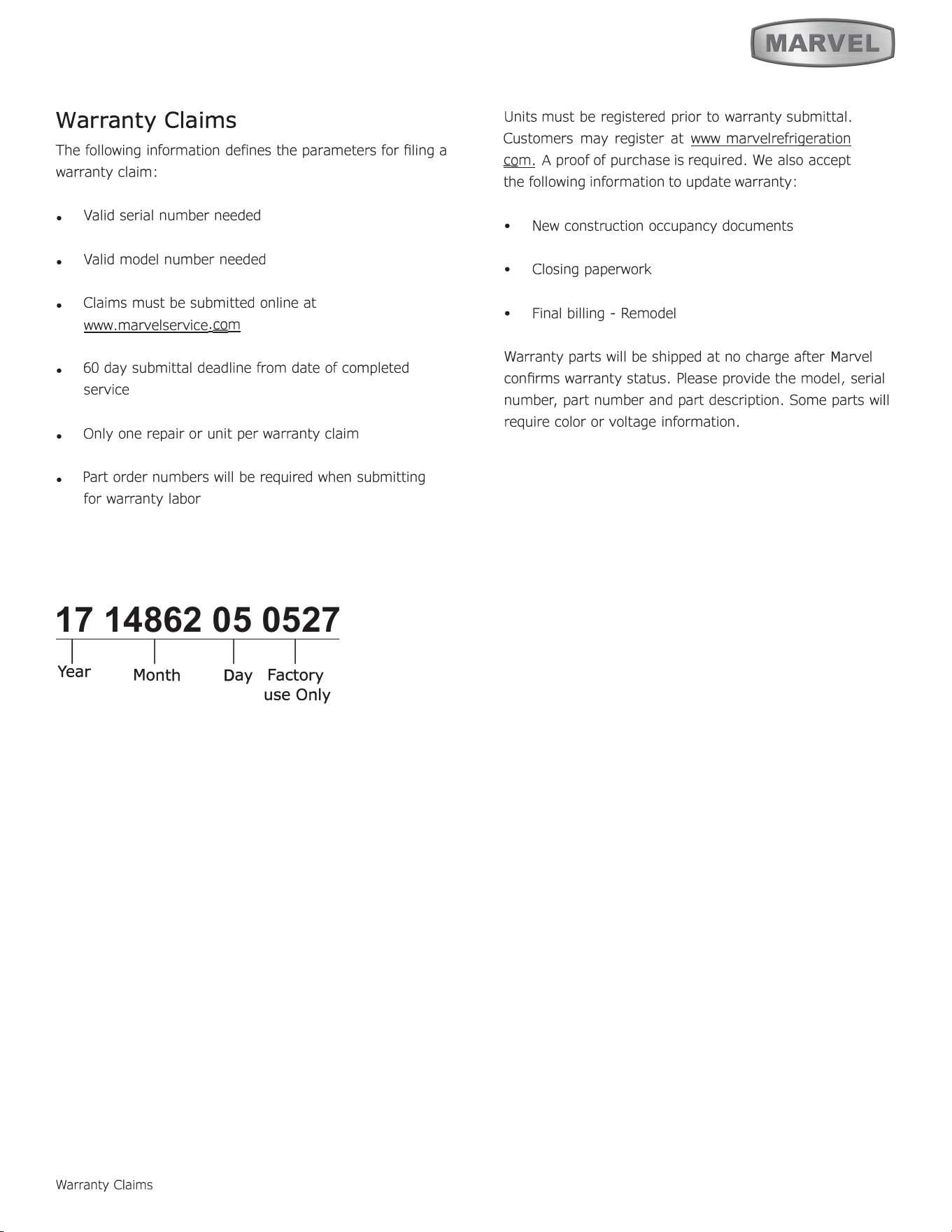
Warranty Claims
The following inrmation defines the parameters for ling a
warranty claim:
• Valid serial number needed
• Valid model number needed
• Claims must be submitted online at
www. marvelservice
.
m
• 60 day submittal deadline from date of completed
service
• Only one repair or unit per warranty claim
• Part order numbers will be required when submitting
for warranty labor
17 14862 05 0527
1
I I I
Year
Warranty Claims
D
ay
Factory
use O
nly
Units must be registered prior to warranty submittal.
Customers may register at www marvelrefrigeration
com. A proof of purchase is required. We also accept
the following information to update warranty:
•
New construction occupancy documents
•
Closing paperwork
•
Final billing - Remodel
Warranty parts will be shipped at no charge aer
M
arvel
conrms warranty status. Please provide the model, serial
number, part number and part description. Some parts will
require color or voltage information.
Month
27
27
29
21
28
14
30
4 26 19 15
20
23
6
7
22 3 5 17 16 18
13
2
8
1
12
11
31
10
9
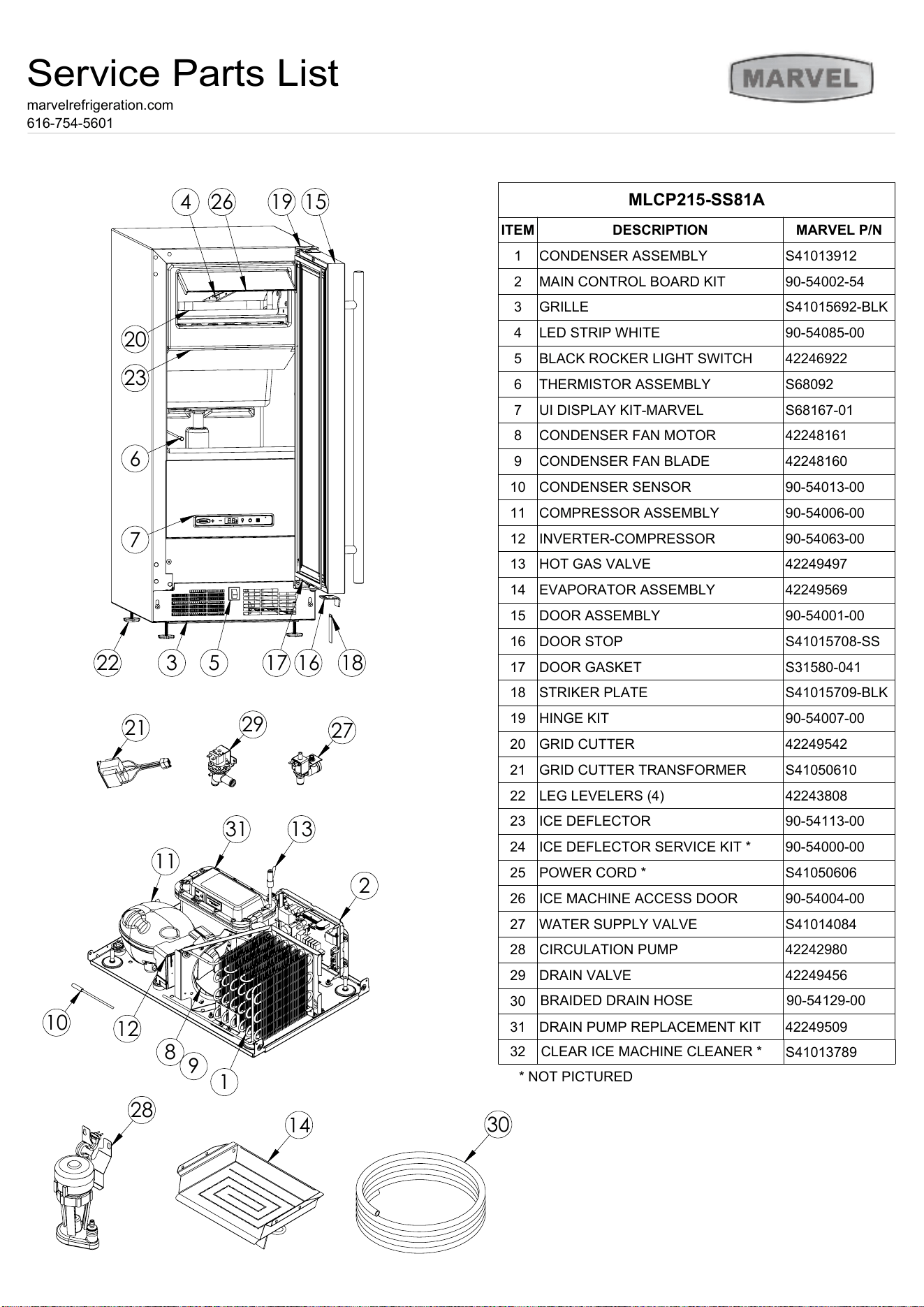
MLCP215-SS81A
ITEM
DESCRIPTION
MARVEL P/N
1
CONDENSER ASSEMBLY
S41013912
2
MAIN CONTROL BOARD KIT
90-54002-54
3
GRILLE
S41015692-BLK
4
LED STRIP WHITE
90-54085-00
5
BLACK ROCKER LIGHT SWITCH
42246922
6
THERMISTOR ASSEMBLY
S68092
7
UI DISPLAY KIT-MARVEL
S68167-01
8
CONDENSER FAN MOTOR
42248161
9
CONDENSER FAN BLADE
42248160
10
CONDENSER SENSOR
90-54013-00
11
COMPRESSOR ASSEMBLY
90-54006-00
12
INVERTER-COMPRESSOR
90-54063-00
13
HOT GAS VALVE
42249497
14
EVAPORATOR ASSEMBLY
42249569
15
DOOR ASSEMBLY
90-54001-00
16
DOOR STOP
S41015708-SS
17
DOOR GASKET
S31580-041
18
STRIKER PLATE
S41015709-BLK
19
HINGE KIT
90-54007-00
20
GRID CUTTER
42249542
21
GRID CUTTER TRANSFORMER
S41050610
22
LEG LEVELERS (4)
42243808
23
ICE DEFLECTOR
90-54113-00
24
ICE DEFLECTOR SERVICE KIT *
90-54000-00
25
POWER CORD *
S41050606
26
ICE MACHINE ACCESS DOOR
90-54004-00
27
WATER SUPPLY VALVE
S41014084
28
CIRCULATION PUMP
42242980
29
DRAIN VALVE
42249456
30
31
DRAIN PUMP REPLACEMENT KIT
42249509
Service Parts List
marvelrefrigeration.com
616-754-5601
32
CLEAR ICE MACHINE CLEANER *
S41013789
* NOT PICTURED
BRAIDED DRAIN HOSE
90-54129-00
28
Ordering Replacement Parts
Parts may be ordered online at
partsformarvel.com
O
r contact:
www.marvelrefrigeration.com
(Servicers choose
"
Login
"
for
service account).
Phone Number: (
6
1
6
) 754-5
6
01
NOTICE
Use only genuine
M
arvel replacement parts. The
use of non-
M
arvel parts can reduce performance,
damage the unit, and void the warranty.
Warranty parts will be shipped at no charge after
M
arvel
confirms warranty status. Please provide the model, serial
number, part number and part description. Some parts will
require color or voltage information.
M
arvel requires the return of original parts, we will inform
you when the parts order is taken. This requirement will
be noted on your packing list. A prepaid shipping label will
be emailed to you. Please enclose a copy of the parts
packing list and be sure the model and serial numbers are
legible on the paperwork. Tag the part with the reported
defect.
Customers and non-authorized servicers may order non
warranty parts at www.partsformarvel.com. Authorized
servicers with a servicer login may order non-warranty
parts at www.marvelrefrigeration.m.
Ordering Replacement Parts
29
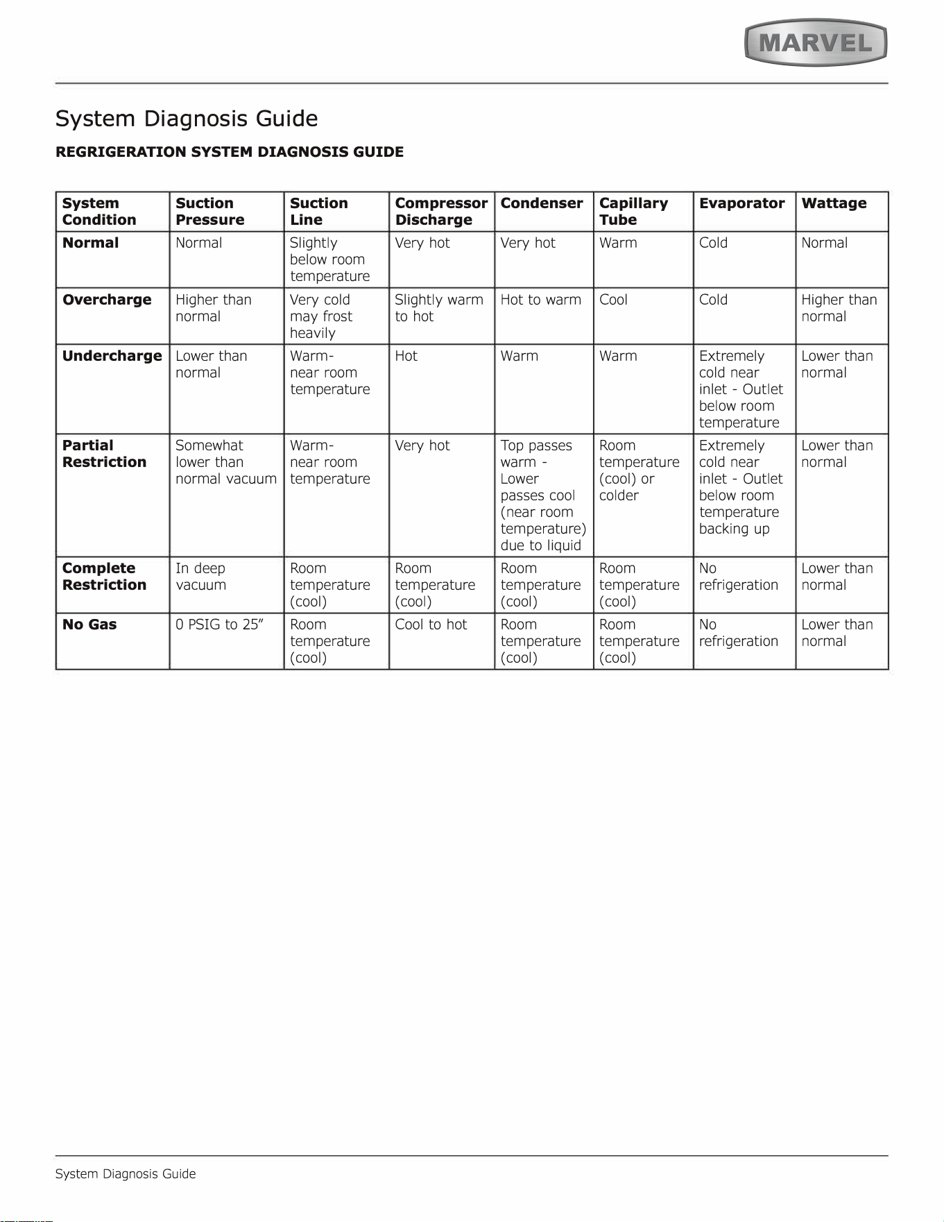
System Diagnosis Guide
REGRIGERATION SYSTEM DIAGNOSIS GUIDE
System
Suction Suction
Compressor
Condition
Pressure
Line
Discharge
Normal Normal Slightly
Very hot
below room
temperature
Overcharge
Higher than
Very cold
Slightly warm
normal
may frost
to hot
heavily
Undercharge
Lower than
Warm- Hot
normal near room
temperature
Partial
Somewhat Warm-
Very hot
Restriction
lower than
near room
normal vacuum
temperature
Complete
In deep
Room Room
Restriction
vacuum
temperature temperature
(cool) (cool)
No Gas
0 PSIG to 25" Room
Cool to hot
temperature
(cool)
System Diagnosis Guide
Condenser
Capillary
Evaporator
Wattage
Tube
Very hot
Warm Cold Normal
Hot to warm
Cool
Cold
Higher than
normal
Warm Warm
Extremely Lower than
cold near
normal
inlet - Outlet
below room
temperature
Top passes
Room
Extremely Lower than
warm -
temperature
cold near
normal
Lower
(cool) or
inlet - Outlet
passes cool
colder
below room
(near room
temperature
temperature)
backing up
due to liquid
Room Room No
Lower than
temperature temperature refrigeration
normal
( cool) (cool)
Room Room No
Lower than
temperature temperature refrigeration
normal
( cool) (cool)
30
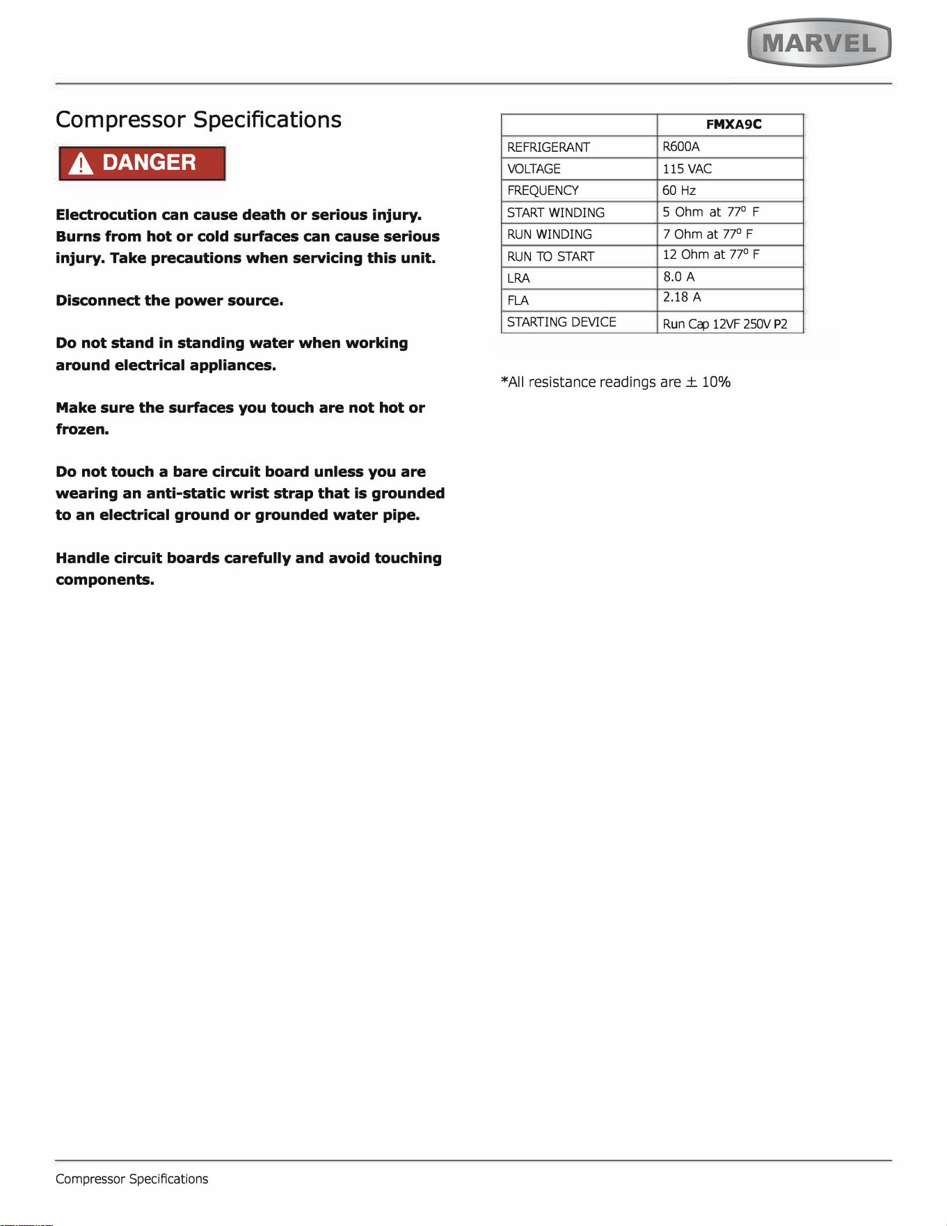
Compressor Specifications
A DANGER
Electrocution can cause death or serious injury.
Burns from hot or cold surfaces can cause serious
injury. Take precautions when seicing this unit.
Disconnect the power source.
Do not stand in standing water when working
around electrical appliances.
Make sure the surfaces you touch are not hot or
frozen.
Do not touch a bare circuit board unless you are
wearing an anti-static wrist strap that is grounded
to an electrical ground or grounded water pipe.
Handle circuit boards carefully and avoid touching
components.
Compressor SpeciAcations
F
MX
A9
C
REFRIGERANT
VOGE
FREQUENCY
START WINDING
R600A
115 VAC
60 Hz
5 Ohm at 77
°
F
RUN WINDING
RUN TO STA
LRA
FLA
SING DEVICE
7
Ohm at 77
°
F
12 Ohm at 77
°
F
8
.0 A
2.18
A
Run c� 12VF 250V P2
*All resistance readings are± 10%
31
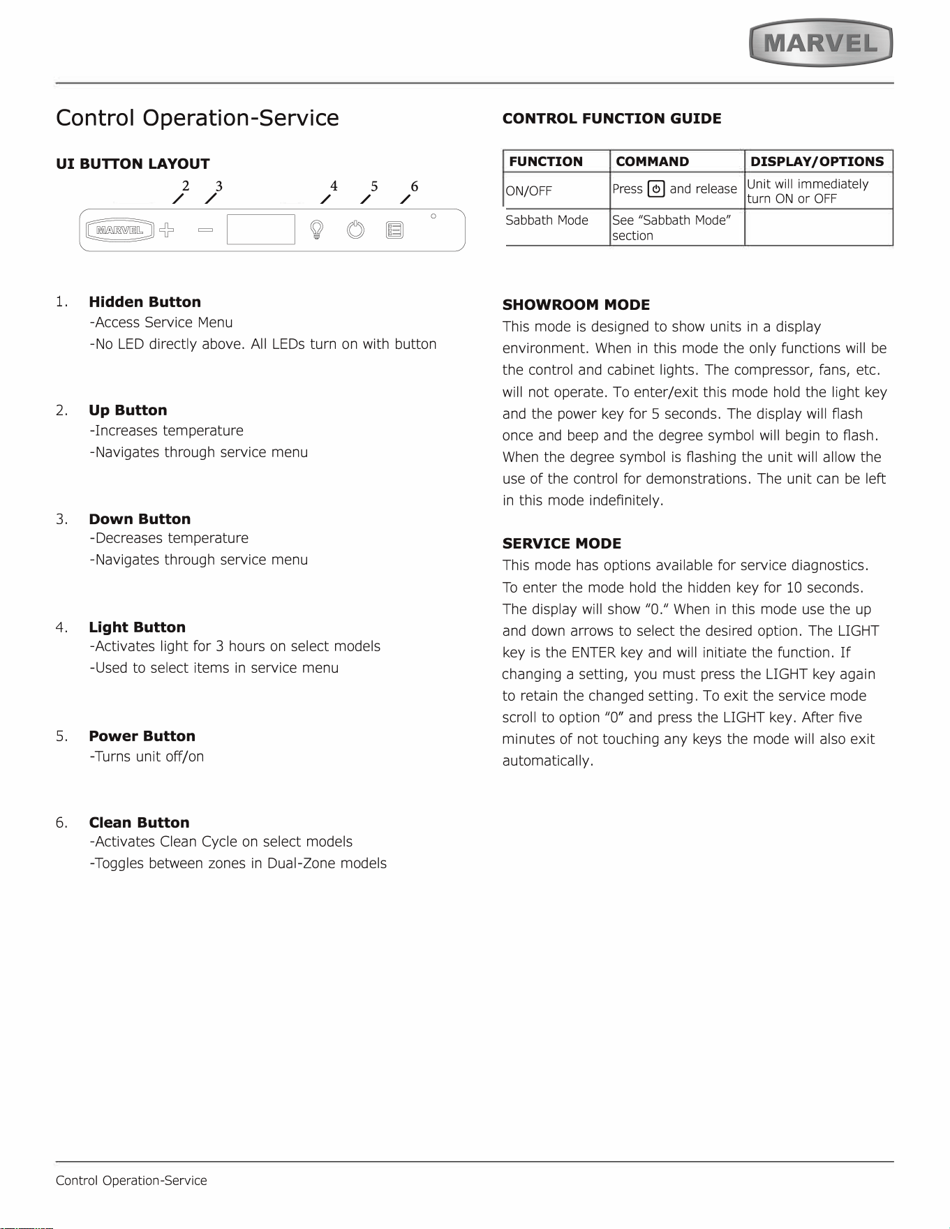
Control Operation-Service
UI BUON LAYOUT
2
3
/ /
1.
Hidden Button
-Access Service Menu
4
5 6
/ / /
-No LED directly above. All LEDs turn on with button
2. Up Button
-Increases temperature
-Navigates through service menu
3.
Down Button
-Decreases temperature
-Navigates through service menu
4. Light Button
-Activates light r 3 hours on select models
-Used to select items in service menu
5.
Power Button
-Turns unit o/on
6.
Clean Button
-Activates Clean Cycle on select models
-Toggles between zones in Dual-Zone models
Control Operation-Service
CONTROL FUNCTION GUIDE
FUNCTION COMMAND
DISPLAY/ OPTIONS
ON/OFF
Press � and release
Unit will immediately
turn ON or OFF
Sabbath Mode See "Sabbath Mode"
section
SHOWROOM MODE
This mode is designed to show units in a display
environment. When in this mode the only functions will be
the control and cabinet lights. The compressor, fans, etc.
will not operate. To enter/exit this mode hold the light key
and the power key for 5 seconds. The display will f1ash
once and beep and the degree symbol will begin to ash.
When the degree symbol is ashing the unit will allow the
use of the control for demonstrations. The unit can be le�
in this mode indefinitely.
SERVICE MODE
This mode has options available for service diagnostics.
To enter the mode hold the hidden key for 10 seconds.
The display will show "O." When in this mode use the up
and down arrows to select the desired option. The LIGHT
key is the ENTER key and will initiate the function. If
changing a setting, you must press the LIGHT key again
to retain the changed setting. To exit the service mode
scroll to option "O" and press the LIGHT key. After Ave
minutes of not touching any keys the mode will also exit
automatically.
32
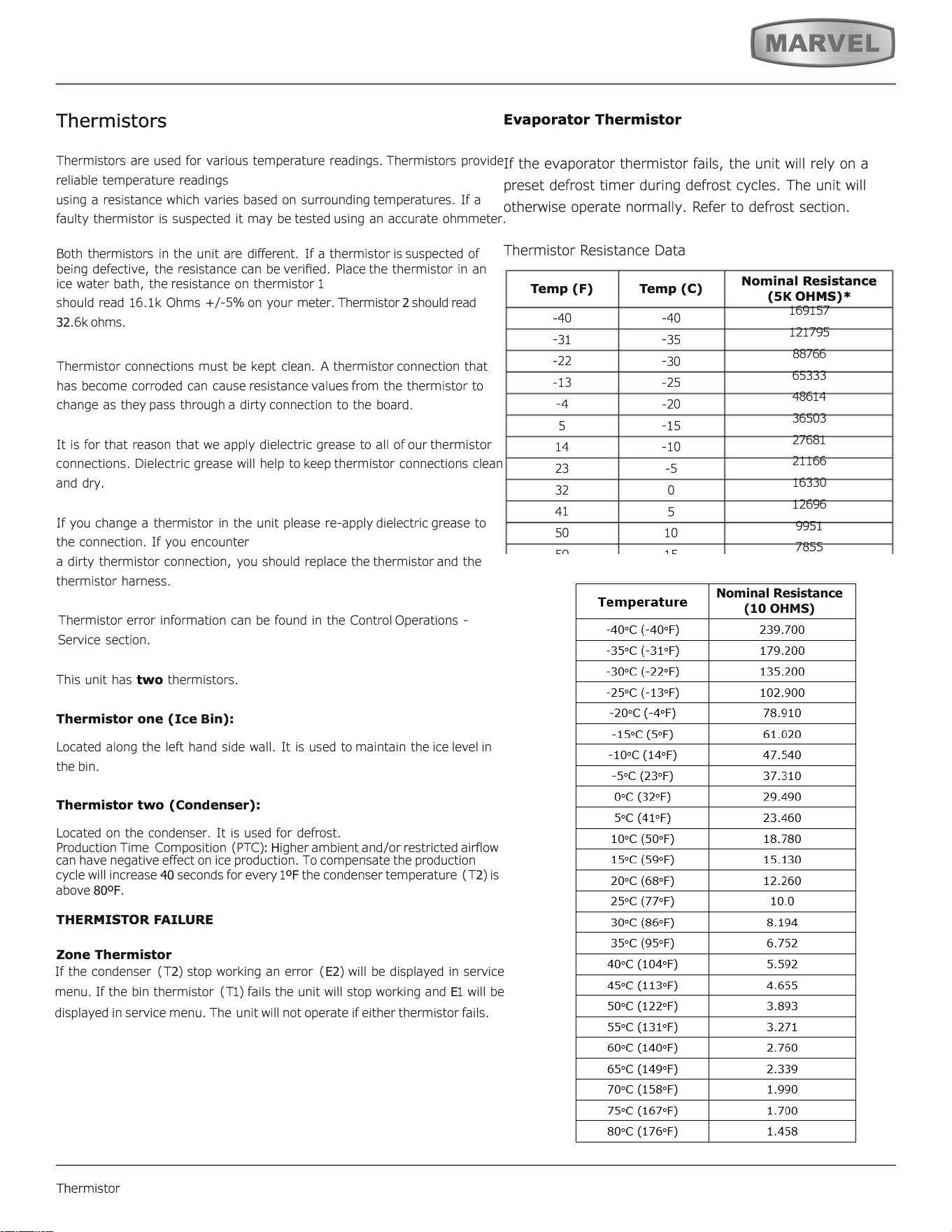
Thermistors
Thermistors ar
e used for various temperature readings. Thermistors provide
reliable temperature readings
using a resistance which varies based on surrounding temperatures.
If a
faulty thermistor is suspected it may be tested using an accurate ohmmeter.
Both thermistors in the unit are different. If a thermistor is suspected of
being defective, the resistance can be veried. Place the thermistor in an
ice water bath, the resistance on thermistor 1
should read 16.lk Ohms +/-5% on your meter. Thermistor
2
should read
32
.6k ohms.
Thermistor connections must be kept clean. A thermistor connection that
has become corroded can cause resistance values from the thermistor to
change as they pass through a dirty connection to the board.
It is for that reason that we apply dielectric grease to all of our thermistor
connections. Dielectric grease will help to keep thermistor connections clean
and dry.
If you change a thermistor in the unit please re-apply dielectric grease to
the connection. If you encounter
a dirty thermistor connection, you should replace the thermistor and the
thermistor harness.
Thermistor error information can be found in the Control Operations -
Service section.
This unit has two thermistors.
Thermistor one (I
c
e
B
in):
Located along the left hand side wall. It is used to maintain the ice level in
the bin.
Thermistor two (
C
on
d
enser):
Located on the condenser. It is used for defrost.
Production Time Composition (PTC)
:
H
igher ambient and/or restricted airflow
can have negative effect on ice production. To compensate the production
cycle will increase
40
seconds for every 1
ºF
the condenser temperature (T
2
) is
above
80ºF
.
THERMISTOR FAILURE
Zone Thermistor
If the condenser (T
2
) stop working an error (
E2
) will be displayed in service
menu. If the bin thermistor (T1) fails the unit will stop working and
E
1 will be
displayed in service menu. The unit will not operate if either thermistor fails.
Thermistor
Evaporator Thermistor
If the evaporator thermistor fails, the unit will rely on a
preset defrost timer during defrost cycles. The unit will
otherwise operate normally. Refer to defrost section.
Thermistor Resistance Data
Temp (F)
Temp (C)
-
40
-
40
-
31
-
35
-
22
-
30
-
13
-
25
-
4
-
20
5
-
15
14
-
10
23
-
5
32
0
41
5
50
10
59
15
68
20
77
25
86 30
95
35
104
40
113
45
122
50
131
55
140
60
149
65
158
70
167
75
176
80
Nominal Resistance
(
5K
OHMS)*
169157
121795
88766
65333
48614
36503
27681
21166
16330
12696
9951
7855
6246
5000
4029
3266
2665
2186
1803
1495
1247
1044
879
743
631
Nominal Resistance
(10 OHMS)
33
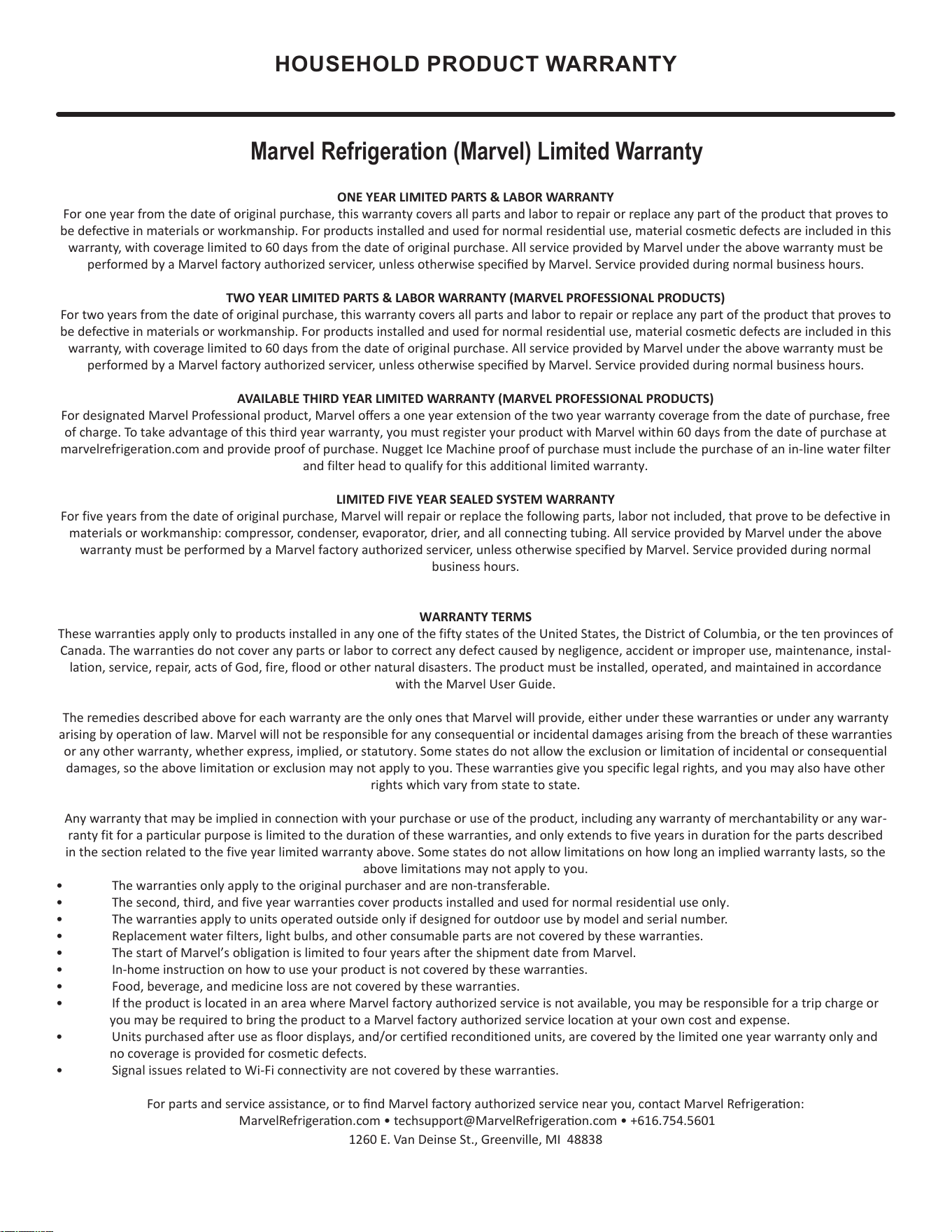
HOUSEHOLD PRODUCT WARRANTY
Marvel Refrigeration (Marvel) Limited Warranty
ONE YEAR LIMITED PARTS & LABOR WARRANTY
For one year from the date of original purchase, this warranty covers all parts and labor to repair or replace any part of the product that proves to
be defecve in materials or workmanship. For products installed and used for normal residenal use, material cosmec defects are included in this
warranty, with coverage limited to 60 days from the date of original purchase. All service provided by Marvel under the above warranty must be
performed by a Marvel factory authorized servicer, unless otherwise specied by Marvel. Service provided during normal business hours.
TWO YEAR LIMITED PARTS & LABOR WARRANTY (MARVEL PROFESSIONAL PRODUCTS)
For two years from the date of original purchase, this warranty covers all parts and labor to repair or replace any part of the product that proves to
be defecve in materials or workmanship. For products installed and used for normal residenal use, material cosmec defects are included in this
warranty, with coverage limited to 60 days from the date of original purchase. All service provided by Marvel under the above warranty must be
performed by a Marvel factory authorized servicer, unless otherwise specied by Marvel. Service provided during normal business hours.
AVAILABLE THIRD YEAR LIMITED WARRANTY (MARVEL PROFESSIONAL PRODUCTS)
For designated Marvel Professional product, Marvel oers a one year extension of the two year warranty coverage from the date of purchase, free
of charge. To take advantage of this third year warranty, you must register your product with Marvel within 60 days from the date of purchase at
marvelrefrigeration.com and provide proof of purchase. Nugget Ice Machine proof of purchase must include the purchase of an in-line water filter
and filter head to qualify for this additional limited warranty.
LIMITED FIVE YEAR SEALED SYSTEM WARRANTY
For five years from the date of original purchase, Marvel will repair or replace the following parts, labor not included, that prove to be defective in
materials or workmanship: compressor, condenser, evaporator, drier, and all connecting tubing. All service provided by Marvel under the above
warranty must be performed by a Marvel factory authorized servicer, unless otherwise specified by Marvel. Service provided during normal
business hours.
WARRANTY TERMS
These warranties apply only to products installed in any one of the fifty states of the United States, the District of Columbia, or the ten provinces of
Canada. The warranties do not cover any parts or labor to correct any defect caused by negligence, accident or improper use, maintenance, instal-
lation, service, repair, acts of God, fire, flood or other natural disasters. The product must be installed, operated, and maintained in accordance
with the Marvel User Guide.
The remedies described above for each warranty are the only ones that Marvel will provide, either under these warranties or under any warranty
arising by operation of law. Marvel will not be responsible for any consequential or incidental damages arising from the breach of these warranties
or any other warranty, whether express, implied, or statutory. Some states do not allow the exclusion or limitation of incidental or consequential
damages, so the above limitation or exclusion may not apply to you. These warranties give you specific legal rights, and you may also have other
rights which vary from state to state.
Any warranty that may be implied in connection with your purchase or use of the product, including any warranty of merchantability or any war-
ranty fit for a particular purpose is limited to the duration of these warranties, and only extends to five years in duration for the parts described
in the section related to the five year limited warranty above. Some states do not allow limitations on how long an implied warranty lasts, so the
above limitations may not apply to you.
• The warranties only apply to the original purchaser and are non-transferable.
• The second, third, and five year warranties cover products installed and used for normal residential use only.
• The warranties apply to units operated outside only if designed for outdoor use by model and serial number.
• Replacement water filters, light bulbs, and other consumable parts are not covered by these warranties.
• The start of Marvel’s obligation is limited to four years after the shipment date from Marvel.
• In-home instruction on how to use your product is not covered by these warranties.
• Food, beverage, and medicine loss are not covered by these warranties.
• If the product is located in an area where Marvel factory authorized service is not available, you may be responsible for a trip charge or
you may be required to bring the product to a Marvel factory authorized service location at your own cost and expense.
• Units purchased after use as floor displays, and/or certified reconditioned units, are covered by the limited one year warranty only and
no
coverage is provided for cosmetic defects.
• Signal issues related to Wi-Fi connectivity are not covered by these warranties.
For parts and service assistance, or to nd Marvel factory authorized service near you, contact Marvel Refrigeraon:
MarvelRefrigeraon.com • techsupport@MarvelRefrigeraon.com • +616.754.5601
1260 E. Van Deinse St., Greenville, MI 48838
34
All specications and product designs subject to change without notice. Such revisions do not entitle
the buyer to corresponding changes, improvements, additions, replacements or compensation for
previously purchased products.
www.marvelrefrigeration.com
Marvel Refrigeration
1260 E. Van Deinse St.
Greenville MI 48838
616.754.5601
35