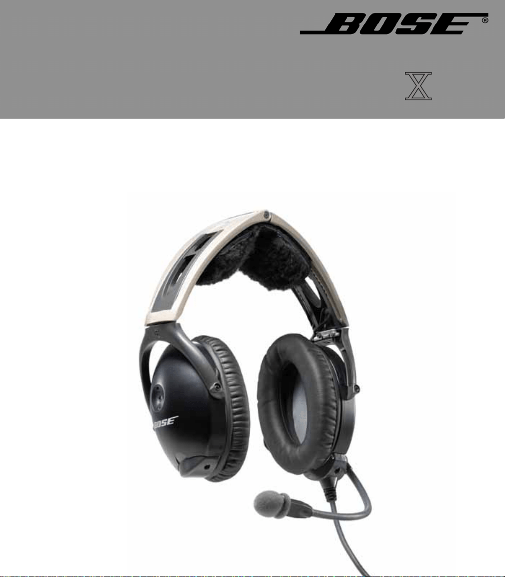
AVIATION HEADSET
©2009 Bose Corporation, The Mountain,
Framingham, MA 01701-9168 USA
AM325239 Rev.00
Owner’s Guide
DECLARATION OF CONFORMITY
We, the offerer:
Bose Corporation,
The Mountain, Framingham, MA 01701-9168 USA
Acknowledge our sole responsibility, that the product:
Kind of equipment: Bose
®
Aviation Headset
Type Designation: AHX-32-0# and AHX-34-0#
In accordance with EMC Directive 89/336/EEC
and Article 10(1) of the Directive,
is in compliance with the following
norm(s) or documents(s)
Technical regulations:EN55013, EN55020
Accredited by:
Bose Corporation, The Mountain, Framingham, MA
01701-9168 USA
Bose Products B.V. Vice President, Europe
Nijverheidstraat 8, 1135 GE Edam Manufacturer’s authorized
The Netherlands EU representative
15 June 2003 Nic Merks
2
00_AM270261-01_HeadsetXII.book Page 2 Tuesday, August 11, 2009 2:27 PM
3
CAUTIONS AND ADVISORIES
Operational advisory
The Bose
®
Aviation Headset is an active noise reducing (ANR)
headset. As with any complex electronic device, it
is possible for this
headset to fail during operation. Symptoms of failure may include
loud tones, distortion, and loss of communications signal in the
headset when used in the ANR mode.
Note: Th
e headset includes redundant circuitry to reduce the effects of such
failures and allow for continued use of the headset in the
ANR mode.
If you experience loud tones and the related loss of communications,
tur
n off the power switch. The headset will continue to provide com-
munications in the passive noise-reducing mode.
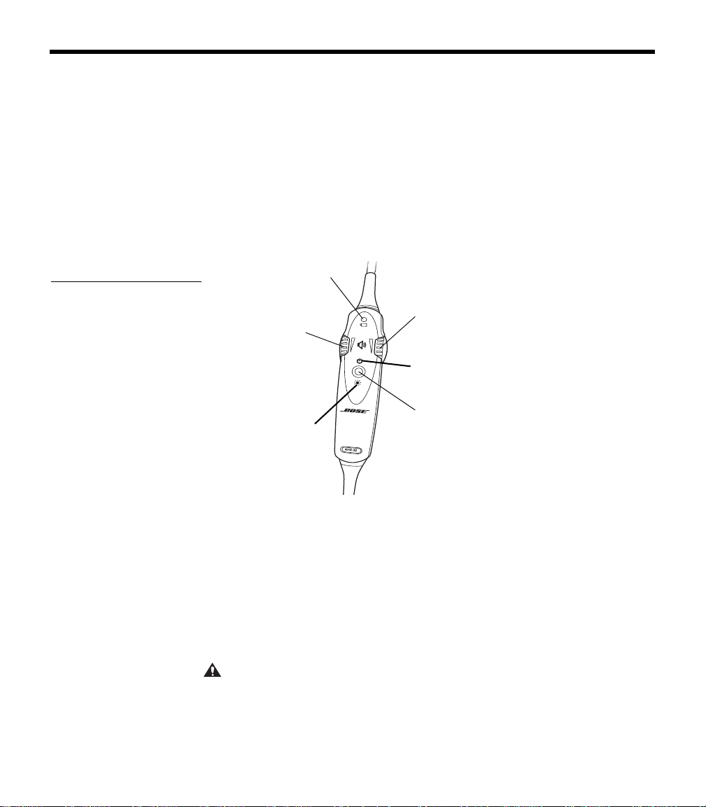
ANR mode is active when the headset control module power switch
is
set to ON (Figure 1) or when the battery power indicator is lit. The
headset is in the passive mode when the
power switch is set to OFF,
or when the battery power indicator is unlit.
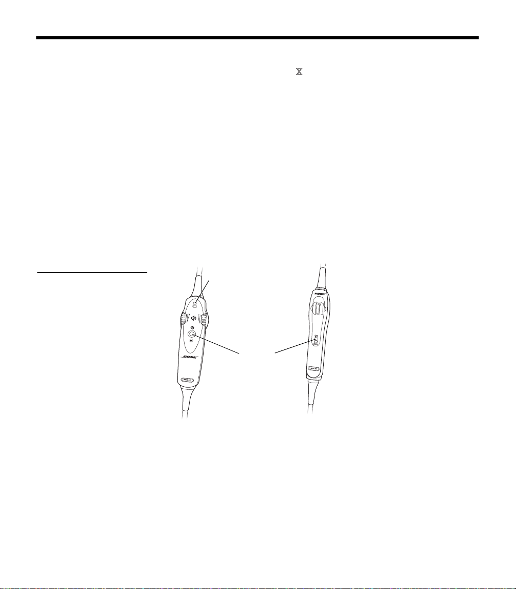
Figure 1
On/Off switch on (a) the
battery powered headset
and (b) the aircraft powered
headset
(b)
(a)
Battery power
indicator
Power
switch
Power source
Your headset is one of two types: battery powered, or aircraft
powered.
If your headset is battery powered, make sure it is connected only to
bat
tery power. If your headset is aircraft powered, connect the head-
set to the aircraft power sources only as described in this guide.
An aircraft powered headset will not operate
properly if used with a
Bose Series II Aviation Headset battery pack or with any commercial
battery pack.
00_AM270261-01_HeadsetXII.book Page 3 Tuesday, August 11, 2009 2:27 PM

4
C
AUTIONS AND ADVISORIES
How use of the headset affects hearing safety
The headset is intended for use with ANR turned on. Noise reduction
and communications performance are reduced with ANR turned off.
Volume control
Make sure your aircraft communications system volume control is
easily accessible. This control affects the strength of the communi-
cations signal coming into the headset, whether ANR is on or off.
As pilot in command, you must be sure you can understand critical
co
mmunications even with ANR off. In this case, you may need to
turn up the aircraft communications system volume.
Avoid setting the volume controls at levels
high enough to impair
your hearing during extended periods of headset use.
Listening to the sounds of your aircraft
With the headset’s active and passive noise reduction, typical aircraft
sounds (from engines, propellers, warning alarms, and other sound
sources) may not sound familiar. We strongly advise you to make
sure you can hear and recognize these sounds when using the Bose
®
Aviation Headset
while operating any aircraft.
Using entertainment audio sources
When listening to in-flight entertainment or a home audio source
through a Bose Aviation Headset
, be sure to limit the volume to
safe levels that do not interfer
e with your ability to hear informational
sounds and warning alarms, such as stall warnings or gear up, while
piloting.
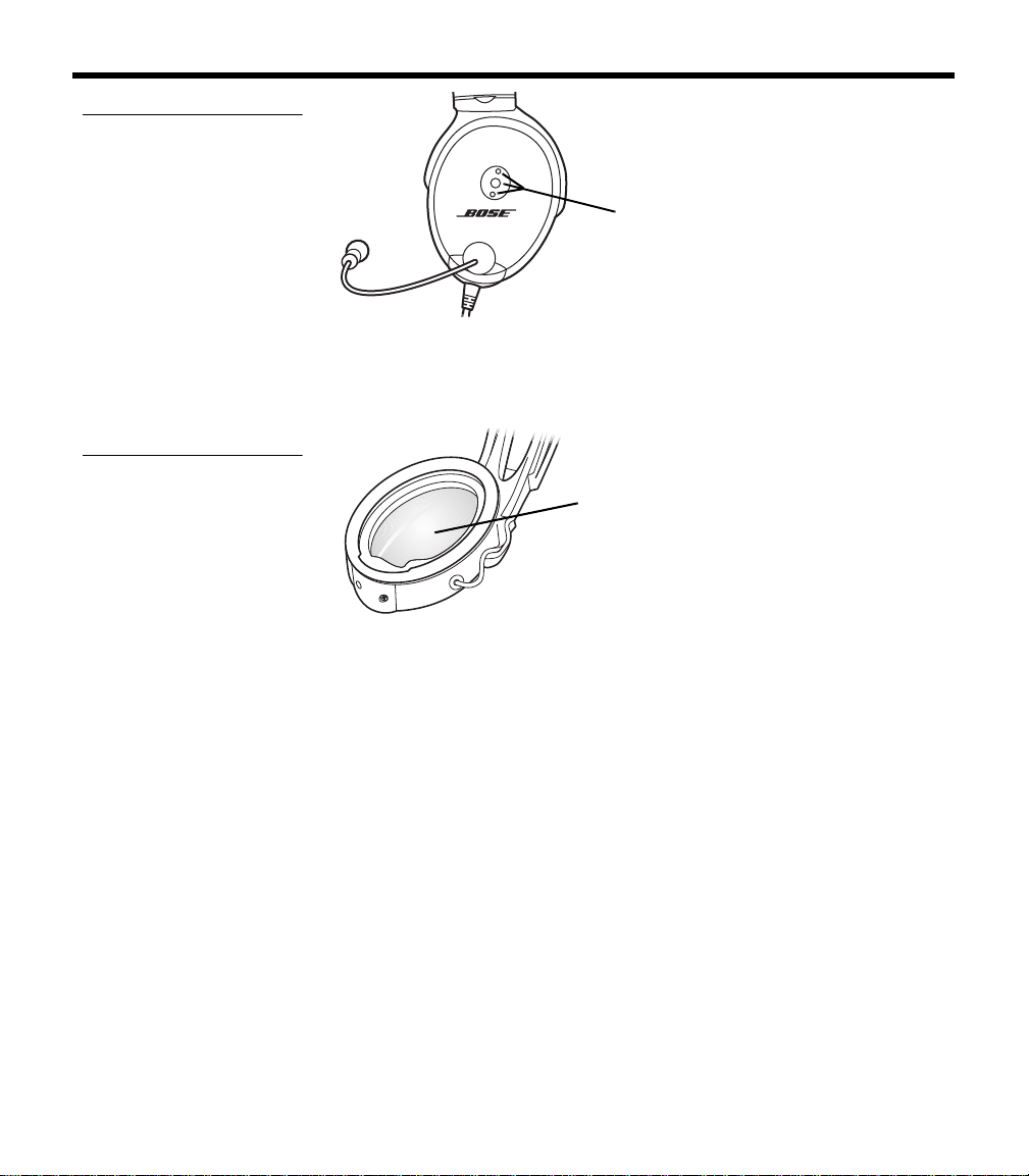
Other cautions
TriPort
®
headset earcup requirements
Proper headset operation requires that the TriPort headset openings
on the earcup are kept free of debris. The TriPort headset openings
(Figure 2 on page 5) are located on the outside of each earcup and
are comprised of two holes and a screen.
00_AM270261-01_HeadsetXII.book Page 4 Tuesday, August 11, 2009 2:27 PM
5
C
AUTIONS AND ADVISORIES
Figure 2
TriPort
®
headset openings
TriPort
headset
openings
Earcup inner screen
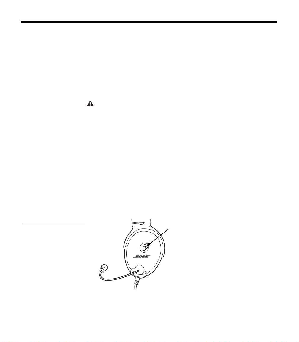
The protective inner screen is critical to the headset’s ability to
reduce noise (Figure 3).
Figure 3
Protective inner screen
inside the earcup
Earcup
inner screen
Do not attempt to remove, replace, or repair this screen. If operating
problems indicate the need for screen replacement, contact the
Bose
®
Aviation Headset Department. Refer to “Contact information”
on page 34.
If the screen gets wet or any foreign objects become lodged
on or adjacent to it, follow the ins
tructions in “Headset Care and
Maintenance” on page 25.
Storage
Do not store the headset in an unventilated area or in direct sunlight.
If your headset is battery powered, remove the batteries before
storing the headset for extended periods.
00_AM270261-01_HeadsetXII.book Page 5 Tuesday, August 11, 2009 2:27 PM

6
CONTENTS
Cautions and Advisories . . . . . . . . . . . . . . . . . . . . . . . . . . . . . . . . . . . . . . 3
Operational advisory . . . . . . . . . . . . . . . . . . . . . . . . . . . . . . . . . . . . . . 3
Power source . . . . . . . . . . . . . . . . . . . . . . . . . . . . . . . . . . . . . . . . . 3
How use of the headset affects hearing safety . . . . . . . . . . . . . . . . . . 4
Volume control . . . . . . . . . . . . . . . . . . . . . . . . . . . . . . . . . . . . . . . . 4
Listening to the sounds of your aircraft . . . . . . . . . . . . . . . . . . . . . 4
Using entertainment audio sources . . . . . . . . . . . . . . . . . . . . . . . . 4
Other cautions . . . . . . . . . . . . . . . . . . . . . . . . . . . . . . . . . . . . . . . . . . . 4
TriPort
®
headset earcup requirements . . . . . . . . . . . . . . . . . . . . . . 4
Earcup inner screen . . . . . . . . . . . . . . . . . . . . . . . . . . . . . . . . . . . . 5
Storage . . . . . . . . . . . . . . . . . . . . . . . . . . . . . . . . . . . . . . . . . . . . . . 5
Contents . . . . . . . . . . . . . . . . . . . . . . . . . . . . . . . . . . . . . . . . . . . . . . . . . . . 6
Introduction . . . . . . . . . . . . . . . . . . . . . . . . . . . . . . . . . . . . . . . . . . . . . . . . 8
We appreciate your choice . . . . . . . . . . . . . . . . . . . . . . . . . . . . . . . . . . 8
Headset and cable variations . . . . . . . . . . . . . . . . . . . . . . . . . . . . 8
Getting Your Headset Ready for Use . . . . . . . . . . . . . . . . . . . . . . . . . . . 10
Locate the serial number for your product registration card . . . . . . . 10
Date of manufacture . . . . . . . . . . . . . . . . . . . . . . . . . . . . . . . . . . 10
Decide where you want the boom microphone . . . . . . . . . . . . . . 10
Removing an attached boom microphone cable . . . . . . . . . . . . . 11
Attaching the boom microphone cable . . . . . . . . . . . . . . . . . . . . 11
Clothing clip . . . . . . . . . . . . . . . . . . . . . . . . . . . . . . . . . . . . . . . . . 12
Preparing to use battery power . . . . . . . . . . . . . . . . . . . . . . . . . . . . . 13
Changing the optional operation switches . . . . . . . . . . . . . . . . . 13
Inserting batteries . . . . . . . . . . . . . . . . . . . . . . . . . . . . . . . . . . . . 14
Preparing the aircraft powered headset for use . . . . . . . . . . . . . . . . . 14
Attaching and removing the cable . . . . . . . . . . . . . . . . . . . . . . . . 14
Mounting the connector . . . . . . . . . . . . . . . . . . . . . . . . . . . . . . . . 15
Details on making the connections . . . . . . . . . . . . . . . . . . . . . . . 16
Use proper adhesives . . . . . . . . . . . . . . . . . . . . . . . . . . . . . . 17
Mono, stereo, and helicopter connection diagrams . . . . . . . 18
Using Your Headset. . . . . . . . . . . . . . . . . . . . . . . . . . . . . . . . . . . . . . . . . 19
Wearing it properly . . . . . . . . . . . . . . . . . . . . . . . . . . . . . . . . . . . . . . . 19
Conditions related to fit . . . . . . . . . . . . . . . . . . . . . . . . . . . . . . . . 19
Microphone placement . . . . . . . . . . . . . . . . . . . . . . . . . . . . . . . . 20
Operating the battery powered headset . . . . . . . . . . . . . . . . . . . . . . 20
Power button . . . . . . . . . . . . . . . . . . . . . . . . . . . . . . . . . . . . . . . . 21
Volume control . . . . . . . . . . . . . . . . . . . . . . . . . . . . . . . . . . . . . . . 21
Notice the individual earcup controls . . . . . . . . . . . . . . . . . . 21
Controlling the volume of a single battery powered headset 22
Volume control using multiple headsets . . . . . . . . . . . . . . . . 22
Battery power indicator . . . . . . . . . . . . . . . . . . . . . . . . . . . . . . . . 22
00_AM270261-01_HeadsetXII.book Page 6 Tuesday, August 11, 2009 2:27 PM

7
C
ONTENTS
Operating the aircraft powered headset . . . . . . . . . . . . . . . . . . . . . . . 23
Power switch . . . . . . . . . . . . . . . . . . . . . . . . . . . . . . . . . . . . . . . . 23
Volume control . . . . . . . . . . . . . . . . . . . . . . . . . . . . . . . . . . . . . . . 23
Notice the individual earcup controls . . . . . . . . . . . . . . . . . . 24
Controlling the volume of a single aircraft powered headset 24
Volume control using multiple headsets . . . . . . . . . . . . . . . . 24
Headset Care and Maintenance . . . . . . . . . . . . . . . . . . . . . . . . . . . . . . . 25
Instructions for continued airworthiness . . . . . . . . . . . . . . . . . . . . . . 25
Cleaning the headset . . . . . . . . . . . . . . . . . . . . . . . . . . . . . . . . . . . . . 25
General cleaning . . . . . . . . . . . . . . . . . . . . . . . . . . . . . . . . . . . . . 25
Earcup TriPort
®
headset openings . . . . . . . . . . . . . . . . . . . . . . . . 25
Ear cushions . . . . . . . . . . . . . . . . . . . . . . . . . . . . . . . . . . . . . . . . 26
Microphone windscreen . . . . . . . . . . . . . . . . . . . . . . . . . . . . . . . 26
Earcup inner screen . . . . . . . . . . . . . . . . . . . . . . . . . . . . . . . . . . . 26
Replacement parts . . . . . . . . . . . . . . . . . . . . . . . . . . . . . . . . 26
Headband cushion . . . . . . . . . . . . . . . . . . . . . . . . . . . . . . . . . . . . 27
Removing environmental moisture . . . . . . . . . . . . . . . . . . . . 27
Replacing parts . . . . . . . . . . . . . . . . . . . . . . . . . . . . . . . . . . . . . . . . . 27
Microphone windscreen replacement . . . . . . . . . . . . . . . . . . . . . 27
Ear cushion replacement . . . . . . . . . . . . . . . . . . . . . . . . . . . . . . . 27
Battery replacement . . . . . . . . . . . . . . . . . . . . . . . . . . . . . . . . . . . 28
Battery door replacement . . . . . . . . . . . . . . . . . . . . . . . . . . . . . . 29
Headband cushion replacement . . . . . . . . . . . . . . . . . . . . . . . . . 29
Boom microphone cable
or connector access cover replacement . . . . . . . . . . . . 29
Troubleshooting . . . . . . . . . . . . . . . . . . . . . . . . . . . . . . . . . . . . . . . . . . . . 30
In case of difficulty . . . . . . . . . . . . . . . . . . . . . . . . . . . . . . . . . . . . . . . 30
Technical Information . . . . . . . . . . . . . . . . . . . . . . . . . . . . . . . . . . . . . . . . 32
FAA Technical Standards Order . . . . . . . . . . . . . . . . . . . . . . . . . . . . . 33
Service & Warranty Information . . . . . . . . . . . . . . . . . . . . . . . . . . . . . . . . 34
Warranty period . . . . . . . . . . . . . . . . . . . . . . . . . . . . . . . . . . . . . . . . . 34
Service . . . . . . . . . . . . . . . . . . . . . . . . . . . . . . . . . . . . . . . . . . . . . . . . 34
To return your headset to Bose for repair . . . . . . . . . . . . . . . . . . 34
Contact information . . . . . . . . . . . . . . . . . . . . . . . . . . . . . . . . . . . . . . 34
Ordering parts and accessories . . . . . . . . . . . . . . . . . . . . . . . . . . . . . 35
00_AM270261-01_HeadsetXII.book Page 7 Tuesday, August 11, 2009 2:27 PM

8
INTRODUCTION
We appreciate your choice
Congratulations on your purchase of a Bose
®
Aviation Headset .
This headset combines Bose Acoustic Noise Cancelling
®
headset
technology to electronically reduce unwanted aircraft noise, and
Bose TriPort
®
headset technology for a smaller, lighter, more
comfortable headset that delivers full-spectrum noise reduction.
We believe it is the finest aviation headset you can own.
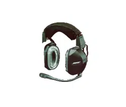
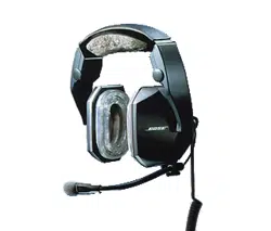
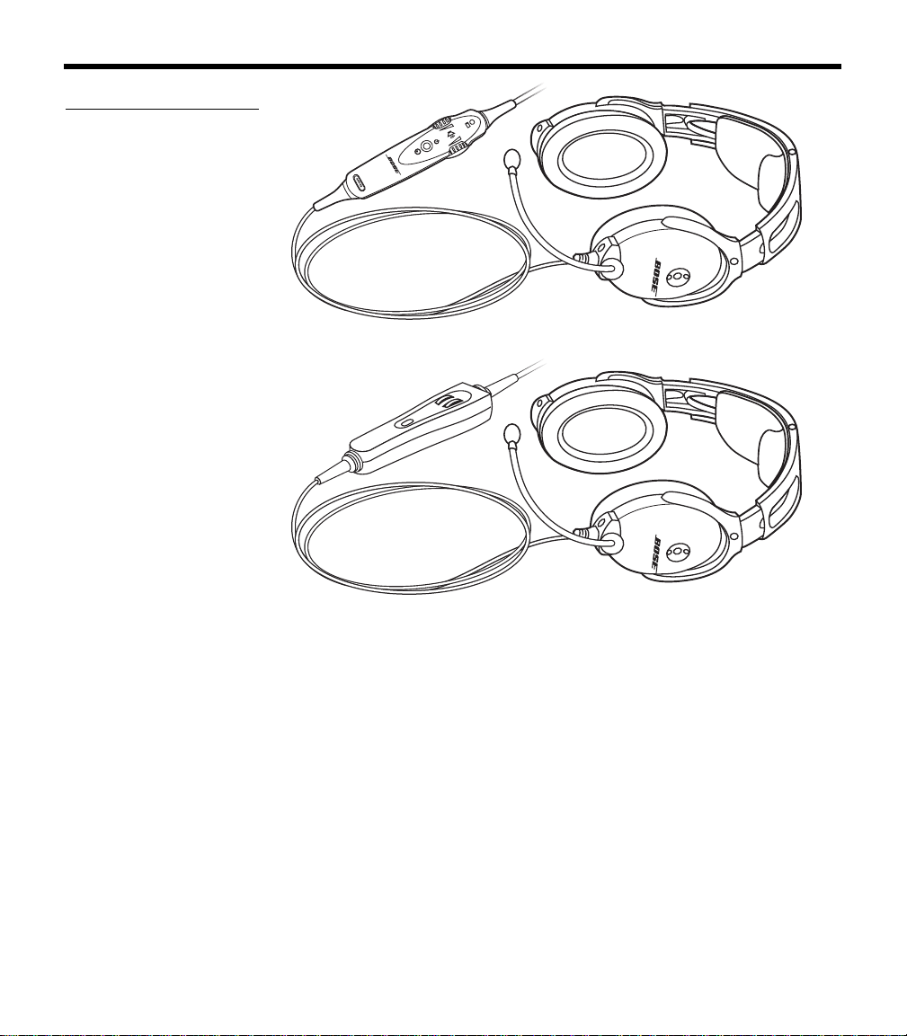
Headset and cable variations
The Bose Aviation Headset is available in variations designed for
general aviation and helicopter use. There are also battery powered
and air
craft powered versions (Figure 4 on page 9).
The communications cable for your headset may be either straight or
c
oiled, depending on the headset configuration you have purchased.
Features common to most variations:
• Acoustic Noise Cancelling headset technology
• TriPort headset technology
• Communications cable with integrated control module
• Flexible microphone boom with continuous position adjustments
• Adjustable headband
• Replaceable ear cushions
• Replaceable fleece headband cushion
• Replaceable windscreen
• Cable-mounted clothing clip
00_AM270261-01_HeadsetXII.book Page 8 Tuesday, August 11, 2009 2:27 PM
9
I
NTRODUCTION
Figure 4
The (a) battery powered
and (b) aircraft powered
versions of the headset
(a)
(b)
00_AM270261-01_HeadsetXII.book Page 9 Tuesday, August 11, 2009 2:27 PM
10
GETTING YOUR HEADSET READY FOR USE
Locate the serial number for your product registration card
The Bose
®
Aviation Headset includes a product registration card in
the carton.
Please fill in the requested information
and mail it to Bose. We will
use this information to provide you with appropriate advisories and
updates. Be sure to include your headset serial number, which can
be found on teh barcode label located on the underside of the
magnesium headband, underneath the headband cushion.
Figure 5
Locating the serial
number under the head-
band cushion
Serial number
Headband
cushion
After locating your headset serial number, be sure to properly replace
the headband cushion by pressing down firmly. For more information
on replacing the headband cushion, see “Headband cushion
replacement” on page 29.
Date of manufacture
Your headset’s date of manufacture is an important part of your serial
number. It is the underlined, four-digit number that begins just after
the first alphabetic letter in the serial number.
Example: 031963E
31920040E
In this example, the date of manufacture is 3192. The first digit, 3,
r
efers to the year of manufacture (200
3). The last three digits, 192,
refer to the day of the year (the 192
nd
day of 2003).
Decide where you want the boom microphone
Depending on the headset configuration you purchased, your head-
set may arrive with the boom microphone cable attached to the left
ea
rcup or packed separately in the carton.
In either case, you can attach the boom microphone cable to either
ea
rcup, as preferred.
00_AM270261-01_HeadsetXII.book Page 10 Tuesday, August 11, 2009 2:27 PM
11
G
ETTING YOUR HEADSET READY FOR USE
Before you remove or attach the microphone, however, be sure to
note the important markings for left (L) and right (R) above each
earcup. These markings indicate which ear each earcup is intended
to fit over.
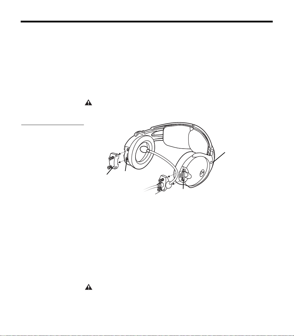
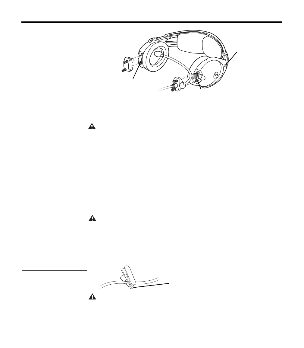
Removing an attached boom microphone cable
1. Use a Phillips or straight blade screwdriver to loosen the two
screws at the base of the boom microphone cable assembly.
2. Pull the cable assembly straight out from the earcup to which it
is
attached (Figure 6).
CAUTION:
Do not twist the boom microphone cable while disconnecting it.
Twisting can damage the connector pins.
Figure 6
Pulling the cable assembly
straight out from the earcup
Access
cover
Connector
pins
Cable
assembly
Connector
pins
L for left
Attaching the boom microphone cable
Before you attach the boom microphone, make sure that the cable
connector and its earcup connector are clean and free of debris.
1. Use a Phillips or straight blade
screwdriver to loosen the two
screws on the access cover near the bottom of the earcup where
you want to attach the boom microphone.
2. Remove the cover to reveal the connector pins on the earcup.
3. Carefully line up the connector to the small connector pins on
th
e panel (Figure 7 on page 12).
CAUTION:
An improperly aligned connector will not make the connections
necessary for proper operation, and may cause damage.
00_AM270261-01_HeadsetXII.book Page 11 Tuesday, August 11, 2009 2:27 PM
12
G
ETTING YOUR HEADSET READY FOR USE
Figure 7
Positioning the mic cable
assembly on the preferred
earcup
Connector
pins
Access
cover
Cable
assembly
Connector
pins
L for left
4. Press the assembly onto the connector pins until it is fully
engaged and the cable assembly is flush with the earcup.
CAUTION:
Do not apply excessive force, which may result in earcup dam-
age.
5. With the screw threads properly aligned, tighten the screws.
6. Rotate the microphone boom
into position so it will be near your
mouth when you put on the headset. The label should be facing
your lips.
7. Attach the access cover to the connector panel on the earcup
t
hat does not have the boom mic attached. Align the screws and
tighten them to secure the cover.
• If you moved the boom mic from one earcup to the other, reuse
the
access cover you removed earlier.
CAUTION:
Be sure to try the headset and test its operation before flight.
Clothing clip
Use the clothing clip (Figure 8) for attaching the control module to
your clothing, a safety harness, or an aircraft door pocket. Pressing
on
the end of the clip allows you to reposition it along the cable.
Figure 8
Moving the clothing clip
along the cable
Press to release
CAUTION: Do not attempt to clip onto surfaces that are more than
1
/
4
-inch thick.
00_AM270261-01_HeadsetXII.book Page 12 Tuesday, August 11, 2009 2:27 PM
13
G
ETTING YOUR HEADSET READY FOR USE
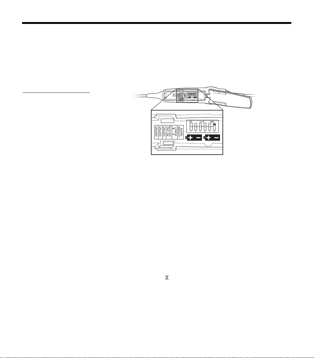
Preparing to use battery power
The battery compartment on your headset control model serves two
purposes. In addition to holding the batteries, it contains small
switches (Figure 9) that give you the option to change some of the
factory-set operation defaults for your headset. Refer to “Battery
replacement” on page 28 for information on opening the battery
compartment.
Figure 9
Optional operation switches
inside the battery compart-
ment
123456
ON C & K S006
AUT
Changing the optional operation switches
Note: To change switch positions, use a pen or a small, flat-tipped screw-
driver to gently switch the tab.
• Switches 1- 3: Not currently used.
• Switch 4: Set at the factory to enable the smart shutoff function. To
disable
smart shutoff, set switch to OFF. With the switch in OFF
position, the ANR system will not turn off until the power button is
depressed and held for at least one second.
Note: Th
e smart shutoff function is designed to detect when the headset is
not in use and shut off ANR to preserve battery power. Smart shutoff turns off
circuitry several minutes after you remove the headset.
• Switch 5: Set to A at the factory for operation with new headsets.
Set it to B if you are installing a portable cable
onto an older, exist-
ing Aviation Headset
that was manufactured before June, 2003.
Note: If you
cannot determine the manufacture date of your headset, refer
to “Locate the serial number for your product registration card” on
page 10.
• Switch 6: Set at the factory for mono audio systems
(to provide
audio in both ears).
Set it for stereo (ST) if your aircraft has a stereo intercom.
00_AM270261-01_HeadsetXII.book Page 13 Tuesday, August 11, 2009 2:27 PM
14
G
ETTING YOUR HEADSET READY FOR USE
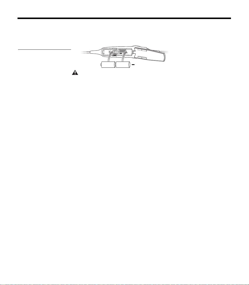
Inserting batteries
Insert the two supplied alkaline AA batteries (IEC LR6) into the
control module (Figure 10).
Figure 10
Installing the two batteries
+
CAUTION: The battery compartment is designed to prevent inadvertent
reverse polarity from installing the batteries incorrectly. If the batteries do
not
seem to fit correctly, do not force them in. Forcing an improper connec-
tion will cause permanent damage to the control module.
Preparing the aircraft powered headset for use
For permanent installation of the headset, the harness (material
number 323172-0010) is installed into the aircraft. The 3-foot
wiring harness includes a self-latching, pr
ecision designed, quick-
connector for panel mounting in the aircraft. The connector is
mechanically keyed to ensure proper mating. To order additional
harnesses, call Bose at 1-800-242-9008.
Note: The aircraft panel connector must be mounted and docu-
mented by qualified personnel to pe
rform this type of avionics
installation into the aircraft being used. Co
nsult your local FAA office
or aviation authorities to determine the appropriate documentation
required.
The Bose connector (material number 323172-0010) is TSO
appr
oved (C-57a and C-58a) together with the Bose Series II
Aviation Headset and the Bose Aviation Headset X.
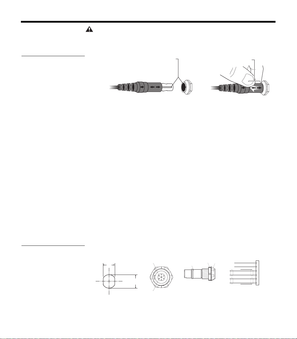
Attaching and removing the cable
When the quick-connector is installed, the cable leading from the
control module connects to it. Match the narrow bar on the cable
end to the slot on the connector. Press in until the two parts engage
(Figure 11 on page 15).
To release the cable, pull back on the sleeve near the end of the
ca
ble. Then gently remove the cable from the connector.
00_AM270261-01_HeadsetXII.book Page 14 Tuesday, August 11, 2009 2:27 PM
15
G
ETTING YOUR HEADSET READY FOR USE
CAUTION: Do not attempt to pull the connector out without first pulling
back on the sleeve. Forcing the connector out
will cause damage to the cable
and/or your aircraft instrument panel.
Figure 11
Attaching and removing the
cable
Slide sleeve
to release
Align keyway
Mounting the connector
Mount the connector into a cutout, as shown in Figure 12 below.
Connect the eight wires as follows:
• Two for the microphone
• Two for audio
•One for power
• One for ground
• Two for audio shields
Audio and microphone wires should be connected to the back of the
ex
isting microphone and headphone jacks, leaving existing jacks
intact for use with conventional headsets. This is usually the fastest
installation method (see Figures 1 – 4 for reference). Audio shields
should be connected to ground at the existing jack.
(Caution: Use of two headsets wired in parallel is
not advised. This
may result in reduced performance.)
Figure 12
Harness connector and
schematic
12.5mm
.49"
.55"
14.0mm
Pin 6
Pin 1
Backnut
Front Nut
M14 X 1
Hex Nut
RED
•
1 V+IN
BLK
•
2 GND
WHT
•
3 COMM L
BLU
•
4 COMM R
WHT
•
5 MIC HI
WH/BLU
•
6 MIC LO
BLK/WH
BLK/WH
Panel Hole
Required
Receptacle -
Pinout
(Front View)
Receptacle -
Backnut
(Side View)
Aircraft
Interface
Schematic
00_AM270261-01_HeadsetXII.book Page 15 Tuesday, August 11, 2009 2:27 PM
16
G
ETTING YOUR HEADSET READY FOR USE
Details on making the connections
The pinout for the optional installed connector is:
Pin Wire color Description
1 Red
Headset power (10-32 VDC). Use a 1/4
amp f
use or a 1/2 amp circuit breaker.
2 Black
System ground. Connect to the existing
au
dio ground.
3 White Phone communication – L
4 Blue Phone communication – R
5 White
Microphone/Hi-audio. Connect to the
p
ortion of the existing microphone jack
that corresponds to the ring position of a
he
adset microphone plug. Do not connect
to the tip (PTT) segment.
00_AM270261-01_HeadsetXII.book Page 16 Tuesday, August 11, 2009 2:27 PM

17
G
ETTING YOUR HEADSET READY FOR USE
Notes
• For use with a stereo intercom, connect the left and right channels
to their respective positions. If your intercom provides a monaural
audio signal, connect pins 3 & 4 together to the tip of the existing
phone jack.
• Do not use excessive force or bend the installed connector.
This may damage or break internal solder joints.
• If the boom microphone works on radio transmit but not through
the intercom, check pin 6. It may be incorrectly wired to the PTT
segment of the microphone jack.
• The wires connecting pins 3 & 4 and pins 5 & 6 are shielded,
twisted pairs with a shield termination exiting with a black/white
wire for each pair. Connect shields to existing audio wiring shields
or to audio ground, if existing wiring is not shielded.
• The Bose aircraft panel connector cannot be installed to an audio
system using transformer-coupled audio outputs. Call the Bose
Aviation Headset Department for details: 800-287-0611.
• Connecting power directly to pins 5 or 6 will result in damage to
the microphone.
• The wire guage is 22 AWG.
Adhesives approved for use with this connector are:
• VTCS-6 Vibratite • Three Bond 1401
Do not let cyanoacrylate-based adhesives, flux remover, or other
caustic compounds contact the connector body. These chemicals
cause irreparable damage to the connector.
18
G
ETTING YOUR HEADSET READY FOR USE
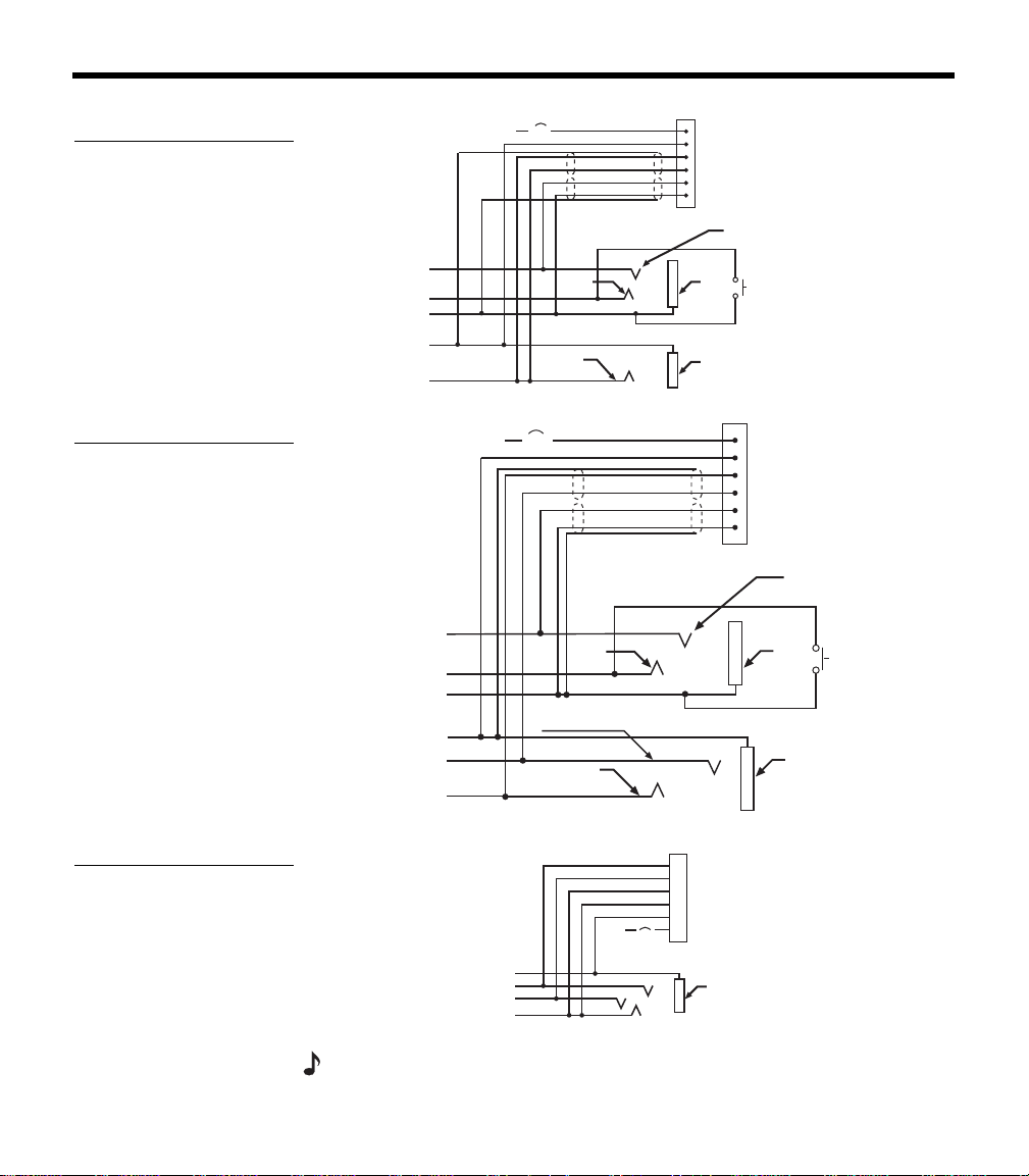
Mono, stereo, and helicopter connection diagrams
Figure 13
Diagram of connections for
a mono signal
10-32
V DC
1/2A
1V+IN
2 GND
3 COMM L
4 COMM R
5 MIC HI
6 MIC LO
RED
BLK
WHT
BLU
WHT
WHT/BLU
BLK/WH
BLK/WH
Ring
(audio)
Exisiting PTT
switch
and wiring
(no connection to
Bose headset)
Microphone - Jack
TPP
(PTT)
Barrel
(gnd)
Headphone - Jack
Barrel
(audio gnd)
Tip
(phone audio)
Existing wiring to
aircraft intercom/
audio panel
Figure 14
Diagram of connections to
aircraft stereo jacks
Existing wiring to
aircraft stereo
intercom/audio panel
10-32
V DC
1/2A
1V+IN
2 GND
3 COMM L
4 COMM R
5 MIC HI
6 MIC LO
RED
BLK
WHT
BLU
WHT
WHT/BLU
BLK/WH
BLK/WH
Audio
Exisiting
PTT switch
and wiring
(no connection to
Bose headset)
Microphone - Jack
TPP
(PTT)
Barrel
(gnd)
Stereo Headphone - Jack
Barrel
(audio gnd)
Tip
(phone audio left)
Phone
audio (right)
Figure 15
Diagram of connections to
a helicopter single jack
Barrel
(audio gnd)
Existing single 4-
prong jack
Existing wiring to
helicopter intercom/
audio panel
10-32
V DC
6 MIC LO
5 MIC HI
4 COMM R
3 COMM L
2 GND
1 V+IN
1/2A
WHT/BLU
WHT
BLU
WHT
BLK
RED
Note: Barrel ground (gnd) refers to aircraft grounds
00_AM270261-01_HeadsetXII.book Page 18 Tuesday, August 11, 2009 2:27 PM
19
USING YOUR HEADSET
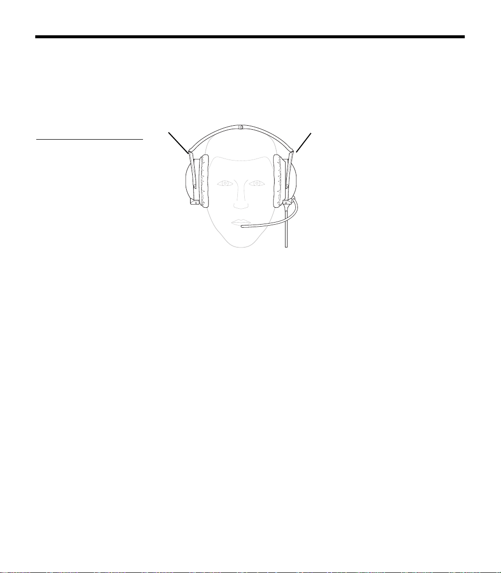
Wearing it properly
Proper fit on your head is important both for comfort and good noise
reduction performance. Here are a few guidelines:
• Use the left (L) and right (R) markings above the earcups to orient
th
e headset properly (Figure 16).
Figure 16
Matching the R and L
markings to your right and
left ears
R
L
• Use a light grasp to adjust each earcup so its cushion is com-
pletely over your ear and you feel an even, gentle pressure all
a
round it.
• Adjust the headband so it rests gently on top of your head.
Make your final adjustments in a noisy environment and with the
p
ower switch set to ON.
Conditions related to fit
A low rumbling sound or frequent brief losses of active noise reduc-
tion (ANR) may indicate an improper fit or blocked earcup ports.
Refer to “Headset Care and Maintenance” on page 25 for instruc-
tions on how to deal with a blockage.
In very loud conditions, such as during takeoff, you may experience
brie
f reductions in ANR as the headset compensates for a momen-
tary pressure change. If this problem continues
when the sound level
returns to normal, however, refer to “In case of difficulty” on page 30.
If the problem persists, contact the Bose
®
Aviation Headset Depart-
ment for assistance.
During a long flight, you may feel a slight pressure point, which can
be r
elieved by adjusting the headband position.
Your experience with using the heads
et will help establish a sense of
how it should sound and feel.
00_AM270261-01_HeadsetXII.book Page 19 Tuesday, August 11, 2009 2:27 PM
20
U
SING YOUR HEADSET
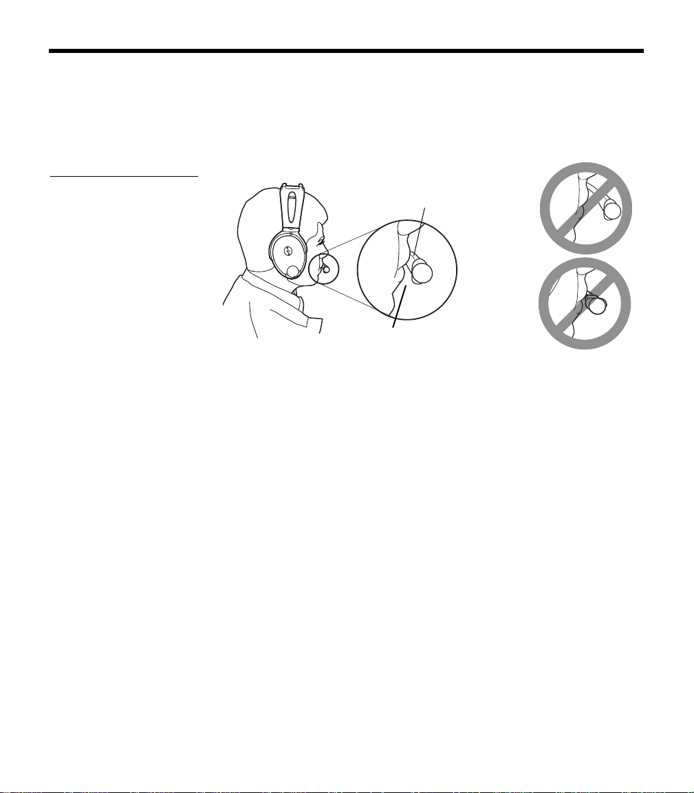
Microphone placement
Proper microphone placement is important for clear communica-
tions. With the headset on your head, make these adjustments:
1. Grasp the boom with your fingers and move the microphone up
or down so it is leve
l with your mouth (Figure 17).
Figure 17
Properly placing the micro-
phone, (a) wide side nearly
touching your mouth, not
(b) farther away or (c) tilted
Mic label
(a)
(b) Mic is too
far away
(c) Mic label
is not facing
mouth
Mic is
1
/
2
inch
from mouth
2. Pull the microphone in toward your lips. Position the microphone
with its label side facing in. Though it will be slightly off center,
the microphone should be
1
/
2
inch from the opening of your lips.
3. Make sure the broad side of the microphone is facing your lips.
Do no
t purse your lips.
Operating the battery powered headset
If your headset is battery powered, read the control information
below. If your headset is aircraft powered, refer to “Operating the air-
craft powered headset” on page 23.
The battery powered headset uses AdaptiS
ense™ headset
technology to supply the power your headset needs at any given
time
. Smart shutoff turns off the circuitry several minutes after you
remove the headset.
This maximizes available energy for longer life from the two batteries.
A tri-color LED pr
ovides real-time battery status. Its brightness is
adjustable for day/night operation.
00_AM270261-01_HeadsetXII.book Page 20 Tuesday, August 11, 2009 2:27 PM
21
U
SING YOUR HEADSET
Power button
Use the power button to turn the headset on or off, or to change the
LED brightness (Figure 18).
• Press the power button once to turn on ANR.
• Press and hold the power button to turn off ANR.
Or rely on the smart shutoff feature (described on page page 13).
Note: Fo
r details on how to disable smart shutoff, see “Changing the
optional operation switches” on page 13.
• Press twice rapidly to toggle between the daytime (brighter) and
nighttime (
dimmer) LED settings.
Figure 18
The LED, volume control
knobs, and power switch
on the control module of a
battery powered headset
Volume control
(left ear)
Volume control
(right ear)
Power button for
On/Off and LED
brightness setting
LED brightness
control symbol
Battery power
indicator
On/Off control
symbol
Volume control
Notice the individual earcup controls
Separate knobs on the control module control the volume for each
se
parate earcup (Figure 18).
Overall headset volume control requires adjustments at both the air-
craft intercom or radio and at the headset control module. Even at its
low
est setting, neither knob on the control module can completely
turn off the volume.
CAUTION:
Avoid setting the volume levels too high. Exposure to loud
sounds may cause hearing damage.
00_AM270261-01_HeadsetXII.book Page 21 Tuesday, August 11, 2009 2:27 PM

22
U
SING YOUR HEADSET
Holding the control module upright and facing you:
• Use the left knob to adjust volume in the left earcup.
• Use the right knob to adjust volume in the right earcup.
Controlling the volume of a singl
e battery powered headset
With ANR on:
1. Set the aircraft communication system to a safe operating level.
2. Turn each volume knob on the headset control module down to
dec
rease, or up to increase the volume of the earcup it controls.
Volume control using multiple headsets
When an aircraft has more than one headset connected to its audio
sys
tem, the pilot in command should adjust the volume of his/her
Bose
®
Aviation Headset as follows:
1. Turn off ANR by setting the power switch to OFF.
2. Turn each volume knob on the headset control module up to its
maximum
setting.
3. Adjust the master volume on your aircraft intercom or radio until
yo
u can hear communications clearly.
Note: Th
is should be done in a noisy environment.
4. Adjust the volume knobs on the headset control module to
balance the volume between the left and right earcups.
5. Turn ANR back ON.
6. Turn down the aircraft intercom or radio master volume to the
lev
el you prefer.
After the pilot’s headset volume is set, passengers may adjust the
volume
of their headsets. Have them follow steps 1 and 2. See “Con-
trolling the volume of a single air
craft powered headset” on page 24.
Battery power indicator
New alkaline AA batteries (IEC LR6) will generally supply 30 to 40
hours of power for the headset. Battery life varies with the ambient
noise level of the aircraft, temperature, ear cushion condition, and
age of the batteries.
00_AM270261-01_HeadsetXII.book Page 22 Tuesday, August 11, 2009 2:27 PM

23
U
SING YOUR HEADSET
An LED, located on the control module, changes color to indicate the
power status, as follows:
LED Color Type of light Indicates
Green Blinking Power ON and batteries good
Amber Fast blinking Power ON, but batteries low
(8 hours or less remaining)
Red Faster blinking Power ON, but batteries very low (2
h
ours or less remaining)
Off None Power OFF or batteries discharged
Operating the aircraft powered headset
Power switch
Turn on ANR by setting the power switch to ON (Figure 19).
Figure 19
The volume control knobs
and power switch on the
aircraft powered headset
control module
Volume control
(left ear)
Volume control
(right ear)
Power switch
Volume control
Overall headset volume control requires adjustments at both the air-
craft intercom or radio and at the headset control module. Even at its
low
est setting, neither knob on the control module can completely
turn off the volume.
00_AM270261-01_HeadsetXII.book Page 23 Tuesday, August 11, 2009 2:27 PM

24
U
SING YOUR HEADSET
CAUTION: Avoid setting the volume levels too high. Exposure to loud
sounds may cause hearing damage.
Notice the individual earcup controls
Separate knobs on the control module control the volume for each
se
parate earcup (Figure 19 on page 23).
Holding the control module upr
ight and facing you:
• Use the left knob to adjust volume in the left earcup.
• Use the right knob to adjust the volume in the right earcup.
Controlling the volume of a singl
e aircraft powered headset
With ANR turned on:
1. Set the aircraft communication system to a safe operating level.
Note: If you
are connecting the headset to your aircraft for the first time,
turn down the master output level of your radio/intercom system to avoid
exposure to high volume levels.
2. Turn each volume knob on the headset control module down to
dec
rease, or up to increase the volume of the earcup it controls.
Volume control using multiple headsets
When an aircraft has more than one headset connected to its audio
sys
tem, the pilot in command should adjust the volume of his/her
Bose Aviation Headset
as follows:
1. Turn off ANR by setting the power switch to OFF.
2. Turn up each volume knob on the headset control module to its
maximum
.
3. Adjust the master volume on your aircraft intercom or radio until
yo
u can hear communications clearly.
Note: Th
is should be done in a noisy environment.
4. Adjust the knobs on the headset control module to balance the
v
olume between the left and right earcups.
5. Turn ANR back ON.
6. Reduce the master volume on the aircraft intercom or radio to
the
level you prefer.
After the pilot’s headset volume is set, passengers may adjust the
vo
lume of their headsets. Have them follow steps 1 and 2 under
“Controlling the volume of a single air
craft powered headset” above.
00_AM270261-01_HeadsetXII.book Page 24 Tuesday, August 11, 2009 2:27 PM
25
HEADSET CARE AND MAINTENANCE
Instructions for continued airworthiness
Bose recommends following the general care and maintenance
instructions in this guide. With normal use, items such as wind-
screens and ear cushions may require periodic replacement. If
cleaning or replacement of these items is needed, follow the
recommendations on the following pages. All other care and
maintenance, in and out of the warranty period, must be performed
by Bo
se or an authorized dealer. Other maintenance is performed by
condition only.
CAUTION:
Do not immerse the headset in water or any other liquid.
Cleaning the headset
Clean only those parts listed below according to the instructions.
General cleaning
Gently wipe the outside surfaces of the headband, connectors, plas-
tic parts, and headband cushion, using a soft cloth moistened with
wa
ter and mild soap. Take special care when cleaning the ear cush-
ions and the outside surfaces of the earcups, as described below.
Earcup TriPort
®
headset openings
The TriPort headset openings, shown in Figure 20, must remain clean
and free of debris. Check to be sure that openings are clean before
ea
ch flight.
Figure 20
TriPort headset openings on
one earcup
TriPort headset
openings
When wiping down the headset, be sure not to force any dirt or
debris into the openings. Carefully use tweezers, if necessary, to
remove foreign matter that may be lodged in the openings. Do not
blow air into or vacuum the openings.
00_AM270261-01_HeadsetXII.book Page 25 Tuesday, August 11, 2009 2:27 PM

26
H
EADSET CARE AND MAINTENANCE
Ear cushions
As a general rule, ear cushions should be replaced every six months
or every 350 hours of use, depending on how often you fly. You may
have to replace them more often, if you:
• have a full beard or heavy whiskers
• subject the headsets to severe temperature extremes such as
parking your airplane outside in severe cold or heat
• put excess strain on the headset due to improper storage
Indications that the ear cushions need replacing include:
• flaking of the outer covering
• cuts or tears
• flattening of the cushion, reducing the effectiveness of the seal
To extend the life of the ear cushions, perform regular cleaning as
described in
“General cleaning” on page 25.
If the ear cushions require more vigorous cleaning, remove them
from the earcups, as shown in
“Replacing parts” on page 27. Do not
immerse ear cushions in water or any other liquid.
Microphone windscreen
Remove the windscreen from the microphone as described in
“Microphone windscreen replacement” on page 27.
Wash the windscreen by immersing in mild soapy water. Rinse, air-
dry, and reattach the windscreen.
Earcup inner screen
Do not attempt to remove, replace, repair, or clean this component.
Located inside the earcup, the inner screen is critical to proper head
-
set operation. If the screen appears to cause operating problems,
contact the Bose
®
Aviation Headset Department.
Replacement parts
Replacement parts can be ordered directly from Bose Corporation.
Please refer to
“Contact information” on page 34.
00_AM270261-01_HeadsetXII.book Page 26 Tuesday, August 11, 2009 2:27 PM
27
H
EADSET CARE AND MAINTENANCE
Headband cushion
1. Remove the cushion as described in “Headband cushion
replacement” on page 29.
2. Place the cushion in a solution of water and a mild detergent.
3. Allow the cushion to air dry, then, reattach.
Removing environmental moisture
If the protective inner screen becomes damp, due to environmental
mo
isture such as light rain, dew, perspiration, or condensation, allow
it to air dry only. Do not use electric heaters, blowers, or hairdryer
type devices to dry the inner screen.
If the headset is immersed in liquid
, do not use it. Contact the Bose
®
Aviation Headset Department for assistance.
Replacing parts
Through normal use, parts like windscreens and ear cushions may
require periodic replacement.
Microphone windscreen replacement
1. Remove the band that secures the windscreen by rolling the
band from the tip of the microphone.
2. Gently pull the windscreen off of the microphone.
3. Slide-on the replacement windscreen and make sure that it fits
co
mpletely over the microphone.
4. Roll a new band to the proper position, about
1
/
4
inch from the
end of the windscreen, to secure it.
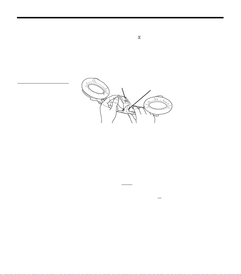
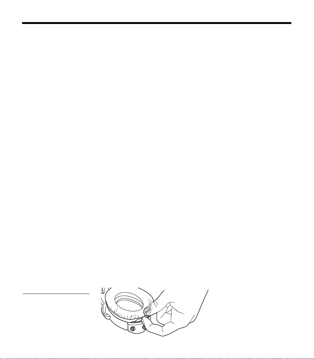
Ear cushion replacement
1. Grasp the ear cushion skirt where it folds into the slot on the
earcup (Figure 21).
2. Gently pull the ear cushion skirt up and away from the earcup.
Figure 21
Pulling the ear cushion skirt
away from the earcup
00_AM270261-01_HeadsetXII.book Page 27 Tuesday, August 11, 2009 2:27 PM
28
H
EADSET CARE AND MAINTENANCE
3. Properly position the replacement ear cushion against the earcup.
4. Tuck an edge of the ear cushion skirt into the slot behind the ear
cu
shion flange. Be careful not to fold the skirt over.
5. Work the remainder of the skirt into the slot completely around
th
e earcup.
6. Grasp the ear cushion and adjust its position to remove any
folds in the skirt and wrink
les in the cushion.
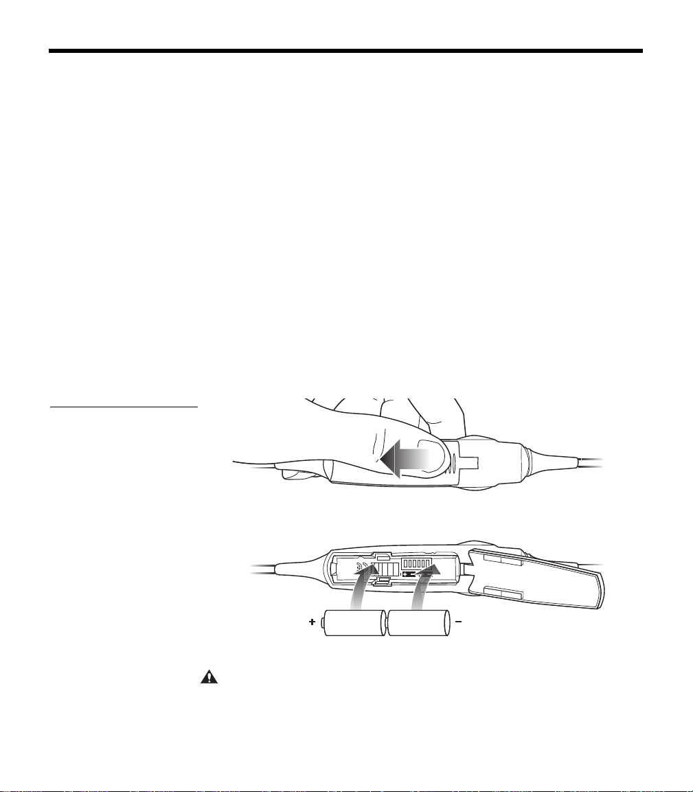
Battery replacement
1. Turn off ANR.
2. While pushing down, slide the battery door using the finger
indent and lift open as shown in Figur
e 22a.
3. Remove the old batteries.
4. Make sure that the battery compartment contacts are clean.
5. Install two AA alkaline batteries
(IEC LR6), as shown in
Figure 22b. Use of rechar
geable batteries, while possible, will
alter the accuracy of the battery power indicator.
Figure 22
a) Sliding open the battery
compartment door
b) Inserting new batteries
into the control module bat-
tery compartment
a)
b)
6. Close the battery door.
CAUTION:
The battery compartment is designed to prevent inadvertent
reverse polarity from installing the batteries incorrectly. If the batteries do not
seem to fit corr
ectly, do not force them in. Forcing an improper connection will
cause permanent damage to the control module.
00_AM270261-01_HeadsetXII.book Page 28 Tuesday, August 11, 2009 2:27 PM
29
H
EADSET CARE AND MAINTENANCE
Battery door replacement
1. Slide the battery door down using the finger indent and lift open.
2. Gently rotate the cover sideways to remove from the control
module.
3. Insert new door tab, being careful to insert between the metal
sp
ring and plastic housing.
Headband cushion replacement
The headband cushion is designed to give the maximum level of
comfort to your headset.
Please follow the maintena
nce instructions below for regular care.
Bose recommends that the cushion be replaced after regular care
and maintenance fails to restore the wool pile to its original size and
shape.
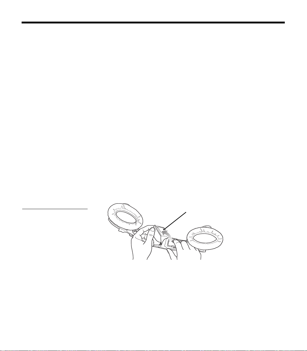
To replace the cushion (Figure 23):
1. On a protected surface, turn the headset upside down. With
a
nother person holding the headset open for you, remove the
old cushion from the magnesium headband.
2. With the headband still held open, align the
center of the new
cushion with the center of the headband and press firmly from
the center toward the outside.
Figure 23
Removing and attaching the
headband cushion
Headband cushion
Note: Removing and attaching the headband cushion may be easier if a
second person holds the headset open.
Boom microphone cable
or connector access cover replacement
Replace the boom microphone cable or connector access cover as
described in “Removing an attached boom microphone cable” and
“Attaching the boom microphone cable” on page 11.
00_AM270261-01_HeadsetXII.book Page 29 Tuesday, August 11, 2009 2:27 PM

30
TROUBLESHOOTING
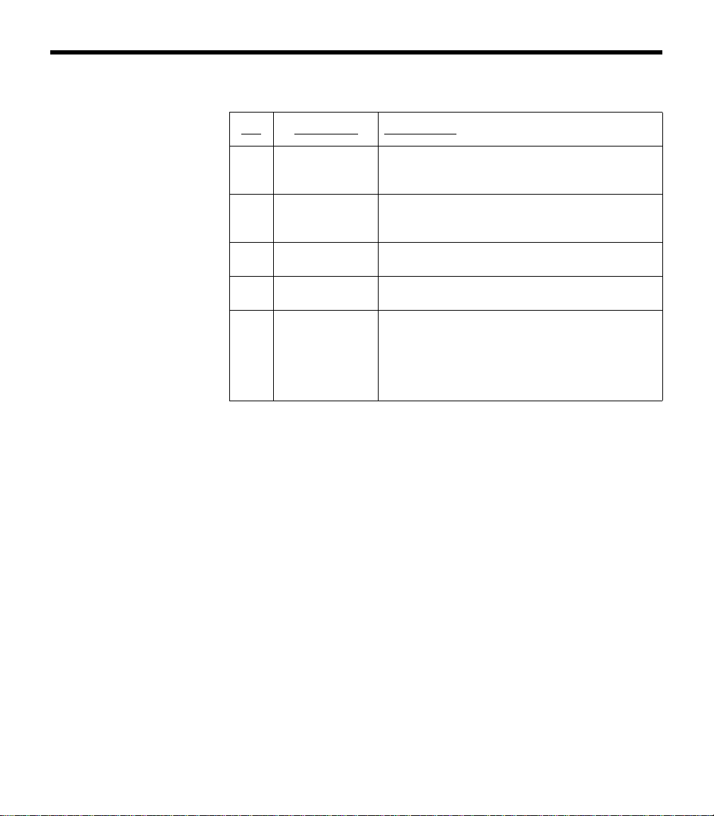
In case of difficulty
Look for the problem in the left column of the table, then follow the
instructions on “What to do” in the right column. If the problem per
-
sists, contact the Bose
®
Aviation Headset Department, using the
contact information on
page 34 of this guide, for assistance.
Problem What to do
Communication, but no
active noise reduction in
either ear
• Make sure the headset ANR is set to ON.
• If using aircraft power, check the aircraft fuse or circuit breaker.
• If using battery power, make sure that the batteries are fresh
and correctly installed.
• Check the battery power indicator. Refer to page 22 for
description of LED indicator.
Active noise reduction, but
no communication, or very
low volume in both ears
• Check to see if the volume controls are set too low. Refer to
“Volume control” on page 21 (battery powered version) or on
page 23 (aircraft powered version) for instructions on volume
adjustment.)
• Check the volume setting of intercom/radio.
• Check the headset aircraft connection.
• Check stereo/mono configuration switch. See “Changing the
optional operation switches” on page 13.
Reduced active noise reduc-
tion, intermittent clicking
sounds, or communication
distortion in a loud environ-
ment
• Check the TriPort
®
headset openings on the outside of each
earcup to ensure they are not blocked. If dust or dirt is present,
carefully remove the debris using tweezers. Do not vacuum or
blow out debris.
Reduced volume in one ear
only
• Check to see if the volume control is set too low. Refer to “Vol-
ume control” on page 21 (battery powered version) or on
page 23 (aircraft powered version) for instructions on volume
adjustment.
• Check stereo/mono configuration switch. See “Changing the
optional operation switches” on page 13.
00_AM270261-01_HeadsetXII.book Page 30 Tuesday, August 11, 2009 2:27 PM

31
T
ROUBLESHOOTING
Stereo missing or communi-
cations in one ear only
• If your aircraft has a mono audio system, verify that the stereo/
mono configuration switch is set to mono. See “Changing the
optional operation switches” on page 13. If the switch is set to
stereo, and the headset is plugged into a mono audio system,
you
will hear only through the left earcup.
Squealing, whistling, or
ch
irping sound when the
system is turned on
• Check to see if the protective inner screen is damaged.
Low rumbling sound with
he
adset turned on in a quiet
environment
• Adjust the earcup fit to create a better seal on your head. The
he
adset’s low-force design makes it sensitive to items that
interfere with the seal around your ear. Make sure that your
ears are completely inside the ear cushions, and that a hat or
eyeglasses with thick temples do not interfere with the seal.
• Check ports at the outside surface of each earcup to ensure
th
ey are not blocked. If dust or dirt is present, carefully remove
the debris using tweezers. Do not blow out or vacuum debris.
• Inspect the seal between the ear cushion skirt and the earcup.
Th
e skirt should enclose the earcup evenly, without gaps.
Replace any cushions that have surface tears, torn stitching
joints, large wrinkles, or have become dried and stiff.
Crackling sound audible with
he
adset turned on in a loud
environment, or ANR is inter-
mittent
• Adjust the earcup fit to eliminate the crackling sound. Refer to
“Wearing it properly” on page 19.
• If your headset is battery powered, check to see if the battery is
low
(indicated by fast blinking red LED).
• If your headset is aircraft powered, make sure that the voltage
powe
ring the headset is greater than 10 VDC.
• Inspect the seal between the ear cushion skirt and the earcup.
Th
e skirt should fit into the slot on the earcup with no gaps.
Replace any cushions that have surface tears, torn stitching
joints, large wrinkles, or have become dried and stiff.
No active noise reduction
an
d no communication
• Check boom microphone cable connection on the bottom of
the earcup.
CAUTION:
Do not attempt to disassemble or service the inside of the earcups or other parts of the head-
set. Only the boom microphone cable, connector access
cover, batteries, battery cover, windscreen, head-
band cushion, and ear cushions are replaceable by the user. For instructions on how to care for the headset
and
how to replace the ear cushions, refer to “Headset Care and Maintenance” on page 25.
00_AM270261-01_HeadsetXII.book Page 31 Tuesday, August 11, 2009 2:27 PM

32
TECHNICAL INFORMATION
Sound pressure levels (SPL) are relative to 20 micropascals.
Headphone Damage could occur to avionics equipment
that is intended for use only with 600-ohm
headsets. If in doubt, consult the avionics
equipment manufacturer.
Impedance Monaural mode: 160 ohms (ON) and 230
ohms (OFF) at 1 kHz
Stereo mode: 320 ohms (ON), 460 ohms (OFF)
Frequency
response
15 Hz to 15 kHz
Sensitivity: 90 dB SPL typical, measured at
1 mw, 1 kHz, full volume on KEMAR ear
simulator
Microphone
(Electret)
Bias required: 8 to 16 VDC through 220 to
2200 ohms
Sensitivity: Varies depending upon bias and
radio AC input impedance. Typical output is
600 mV at 114 dB SPL. To assure proper
modulation of the radio, it is recommended
that an avionics technician adjust its input to
match the output of the microphone.
Microphone
(Dynamic)
Impedance: 5 ohm or 150 ohm
Sensitivity: Equivalent to M-87/M-101
Maximum ambi-
ent noise level
115 dBC and 105 dBA SPL
Power source Battery powered: 2 AA alkaline, IEC LR6
Aircraft powered: 10 to 32 VDC
Battery life Alkaline: At least 40 hours in typical general
aviation aircraft noise. Battery life varies with
ambient noise level, temperature, ear cushion
condition and age of batteries.
Current Operating: 25 ma in typical aircraft noise
Fuse/breaker
recommended
1
/
4
-amp, fast-blow fuse (AGC
1
/
4
-amp fuse) or
1
/
2
-amp circuit breaker
00_AM270261-01_HeadsetXII.book Page 32 Tuesday, August 11, 2009 2:27 PM

33
T
ECHNICAL INFORMATION
FAA Technical Standards Order
The Bose
®
Aviation Headset , including its interface, cables, and
electret boom microphone, is FAA approved to TSO C-57a and
C-58a. It has been designed to function in or withstand exposure to
the
following environmental conditions:
Condition Category
AF Conducted Susceptibility B
Humidity B
Magnetic effect B
Power input B
RF susceptibility T
Temperature & altitude A1
Vibration S & U
Voltage spike A
Shock drop 12 times, 1m,
ont
o concrete
Environmental categories cited refer to RTCA/DO-160D,
July 29, 1997 and DO-214, March 4, 1993.
Headset weight 12 ounces (340 grams) on the head when
ca
ble is supported by the mounting clip
Headset size
range
Breadth: 4.8 to 6.3 inches
Height: 4.5 to 5.7 inches
Temperature and
Altit
ude
(Category A)
Operating: 5 to 131°F (-15 to 55°C)
Storage: -67 to 158°F (-55 to 70°C)
Altitude: 15,000 feet maximum pr
essure alti-
tude for full cancellation
00_AM270261-01_HeadsetXII.book Page 33 Tuesday, August 11, 2009 2:27 PM

34
SERVICE & WARRANTY INFORMATION
Warranty period
Limited 5-year warranty: Bose Corporation warrants this headset to
be free from defects in materials and workmanship for a period of
five years from the date of purchase. Ear cushion life will vary with
use. Ear cushions carry a six-month limited warranty against manu
-
facturer’s defects.
Service
Contact Bose
for:
• Spare parts and accessories (see page 35)
• Technical advice
• Installation information
• Warranty and repair information
To return your headset to Bose for repair
1. Call to request return authorization instructions from Bose.
2. Clearly mark the return information given to you on the outside
of the package.
3. Enclose your name, address, daytime telephone number and
e-mail address, along with a description of the problem.
4. Securely pack the headset.
5. We recommend that you insure the headset and use a transport
service that provides a tracking number.
6. Send your headset to this address:
Contact information
Bose Aviation Headset Department
145 Pennsylvania Avenue
Framingham, MA 01701-9168 USA
TEL: 1-800-233-4416 (US)
508-879-7330, ext. 62006 (outside US)
FAX: 1-508-766-5997
00_AM270261-01_HeadsetXII.book Page 34 Tuesday, August 11, 2009 2:27 PM

35
S
ERVICE & WARRANTY INFORMATION
European Headquarters:
Noise Reduction Technology Group
Nijverheidstraat 8 NL-1135 GE Edam
TEL:+31(0)299-390150
FAX:+31(0)299-390109
E-MAIL: av[email protected]om
World Wide Web: www.bose.com
Ordering parts and accessories
The following accessories and customer-replaceable components
may be purchased directly from Bose. Refer to contact information
on
page 34.
• Additional control module cable
Specify: battery powered; or aircraft powered
• Ear cushions
•Carry bag
• Windscreen with attachment band
• Aircraft panel connector installation kit
• Battery door
• Fleece headband cushion
• Clothing clip
00_AM270261-01_HeadsetXII.book Page 35 Tuesday, August 11, 2009 2:27 PM
AVIATION HEADSET
©2009 Bose Corporation, The Mountain,
Framingham, MA 01701-9168 USA
AM325239 Rev.00
Owner’s Guide