Loading ...
Loading ...
Loading ...
- 12 -
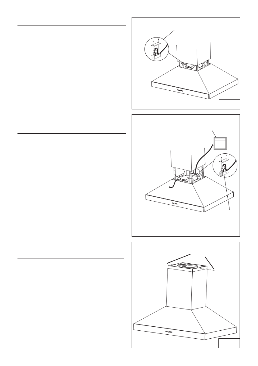
WIRING (IPP9IQT)
Note: This range hood must be properly
grounded. The unit should be installed by a
qualified electrician in accordance with all
applicable national and local electrical
codes.
1. Remove the wiring box cover. Remove a
knockout from the wiring box (Fig.12).
2. Secure the conduit to the wiring box through
a conduit connector.
3. Make electrical connections. Connect white
to white, black to black and green to green.
4. Replace wiring box cover and screws.
Make sure that wires are not pinched
between cover and box.
ADDITIONAL EXTERNAL
BLOWER WIRING (IPP9E)
1. Run 2-wire plus ground power cable from
the exterior blower to the hood’s wiring box
marked “motor connection” (Fig.13).
2. Remove the cover from the wiring box and
remove one knockout.
3. Feed 6” of cable through the knockout
opening and secure the cable to the wiring
box with an appropriate connector.
4. Make electrical connections at the hood.
Connect white-to-white, red-to-black and
green-to-ground.
5. Replace the wiring box cover and screws.
Make sure wires are not pinched between
the cover and box.
Exterior blower connection:
1. Make electrical connections at the exterior
blower (see instructions provided with the
exterior blower).
Once wiring operations are complete,
remove tape and slide down the lower flue .
CONNECT DECORATIVE FLUE
1. Attach the upper flue to the upper
support frame with the mounting screws
3,9x9,5mm (Fig.14).
2. Lower the lower flue in place.
WIRING BOX
COVER
EXTERIOR BLOWER
BLOWER CONNECTION AT HOOD
BOX MARKED
“MOTOR
CONNECTION”
CONNECT:
WHITE-TO-WHITE,
RED-TO-BLACK,
GREEN-TO-GROUND.
FIG.13
FIG.12
FIG. 14
MOUNTING
SCREWS
3,9x9,5mm
Loading ...
Loading ...
Loading ...