Use, Care, and Installation Guide
Model number:
Serial Number:
www.zephyronline.com
JAN17.0101 © Zephyr Ventilation LLC.
Airflow Control Technology
TM
C
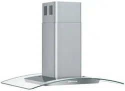
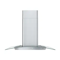
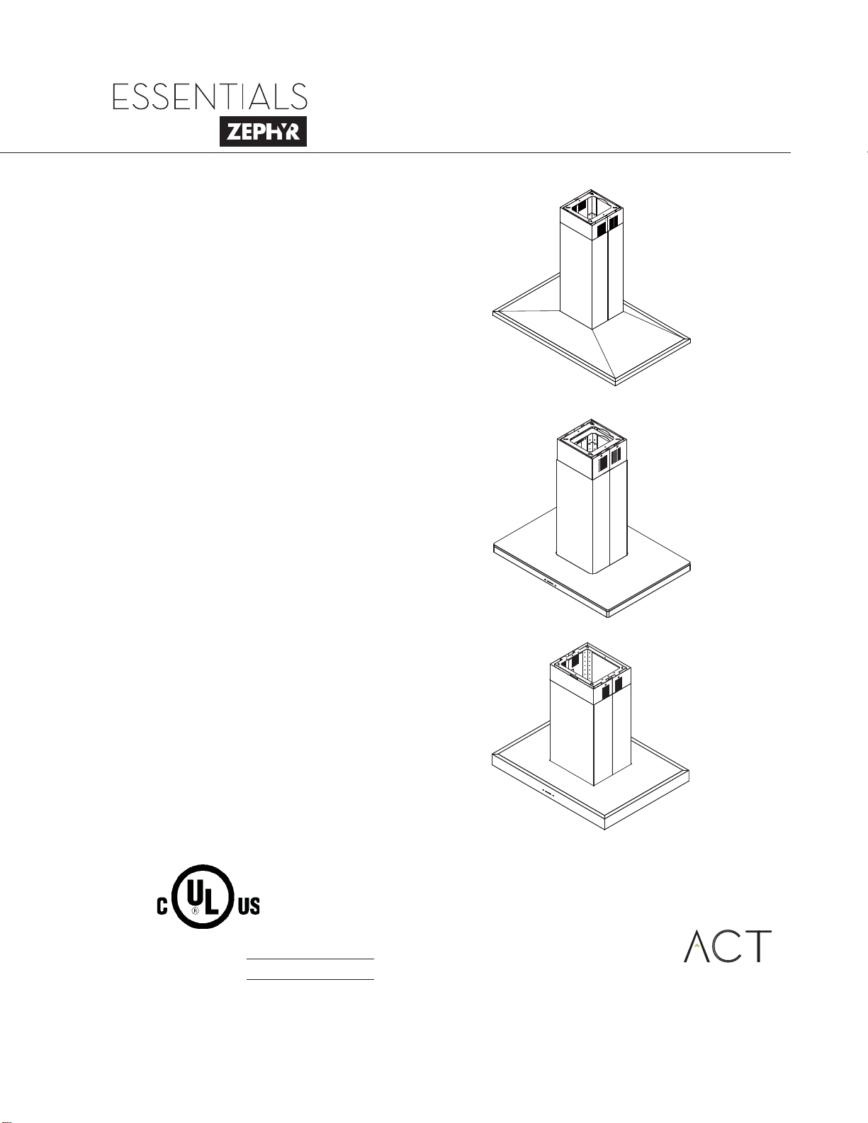
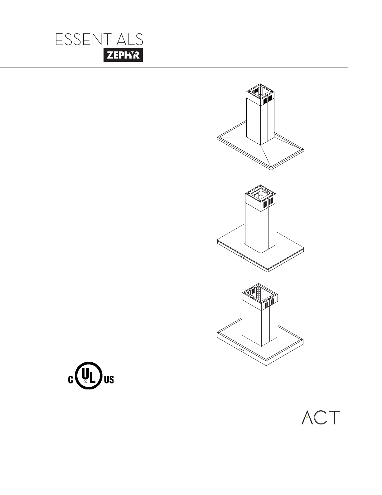
Anzio Island
ZAZ-M90CS
ZAZ-E42CS
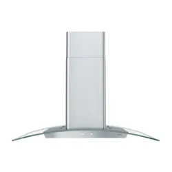
Luce Island
ZLC-M90BS
ZLC-E42BS
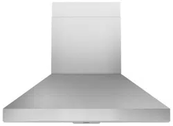
Roma Island
ZRM-E36DS
ZRM-E42DS

www.zephyronline.com

1
SAFETY NOTICE ................................................................. 2-3
LIST OF MATERIALS ....................................................... 4
INSTALLATION
Ducting Calculation Sheet
....................................... 5
Mounting Height & Clearance
................................ 6
Ducting Options
........................................................... 7
+RRG6SHFL¿FDWLRQV
................................................... 8-10
Mounting the Hood
..................................................... 11-12
Ductless Recirculating
.............................................. 13
FEATURES & CONTROLS
ICON Touch Controls ..................................... 14-15
MAINTENANCE
Hood and Filter Cleaning
......................................... 16
TROUBLESHOOTING
................................................................ 17
ACT CONVERSION
..................................................................... 18
FAN CURVE DIAGRAMS
......................................................... 19-20
WIRING DIAGRAM
...................................................................... 21
LIST OF PARTS AND ACCESSORIES
.............................. 22
WARRANTY
.................................................................................... 23
PRODUCT REGISTRATION
.................................................... 24
Table of Contents

Important Safety Notice
READ AND SAVE THESE INSTRUCTIONS
2
www.zephyronline.com
WARNING
TO REDUCE THE RISK OF FIRE OR ELECTRIC SHOCK, DO NOT USE THIS FAN WITH ANY SOLID-STATE CONTROL DEVICE.
WARNING
TO REDUCE THE RISK OF FIRE ELECTRIC SHOCK, OR INJURY TO PERSONS, OBSERVE THE FOLLOWING:
a. Use this unit only in the manner intended by the manufacturer, if you have questions, contact the manufacturer.
b. Before servicing or cleaning unit, switch power off at service panel and lock panel to prevent power from being switched on accidentally.
When the service disconnecting means cannot be locked, securely fasten a prominent warning device, such as a tag, to the service
panel.
CAUTION
For general ventilating use only. Do not use to exhaust hazardous or explosive materials and vapors. Take care when using cleaning
agents or detergents. Suitable for use in household cooking area.
WARNING
TO REDUCE THE RISK OF RANGE TOP GREASE FIRE:
a. Never leave surface units unattended at high settings. Boilovers cause smoking and greasy spillovers that may ignite. Heat oils slowly
on low or medium settings.
E $OZD\VWXUQKRRG21ZKHQFRRNLQJDWKLJKKHDWRUZKHQÀDPLQJIRRG
F &OHDQYHQWLODWLQJIDQVIUHTXHQWO\*UHDVHVKRXOGQRWEHDOORZHGWRDFFXPXODWHRQIDQRU¿OWHU
d. Use proper pan size. Always use cookware appropriate for the size of the surface element.
H .HHSIDQ¿OWHUVDQGJUHDVHODGHQVXUIDFHVFOHDQ
f. Use high setting on hood only when necessary.
g. Don’t leave hood unattended when cooking.
h. Always use cookware and utensils appropriate for the type of and amount of food being prepared.
WARNING
TO REDUCE THE RISK OF INJURY TO PERSONS IN THE EVENT OF A RANGE TOP FIRE, OBSERVE THE FOLLOWING:
D 6027+(5)/$0(6ZLWKDFORVH¿WWLQJOLGFRRNLHVKHHWRUPHWDOWUD\WKHQWXUQRIIWKHEXUQHU%(&$5()8/7235(9(17%8516
,IWKHÀDPHVGRQRWJRRXWLPPHGLDWHO\(9$&8$7($1'&$//7+(),5('(3$570(17
b. NEVER PICK UP A FLAMING PAN – You may be burned.
c. DO NOT USE WATER, including wet dishcloths or towels – a violent steam explosion will result.
d. Use an extinguisher ONLY if:
1. You know you have a Class ABC extinguisher, and you already know how to operate it.
7KH¿UHLVVPDOODQGFRQWDLQHGLQWKHDUHDZKHUHLWVWDUWHG
7KH¿UHGHSDUWPHQWLVEHLQJFDOOHG
<RXFDQ¿JKWWKH¿UHZLWK\RXUEDFNWRDQH[LW
WARNING
TO REDUCE THE RISK OF FIRE, ELECTRIC SHOCK OR INJURY TO PERSONS, OBSERVE THE FOLLOWING:
D ,QVWDOODWLRQZRUNDQGHOHFWULFDOZLULQJPXVWEHGRQHE\TXDOL¿HGSHUVRQVLQDFFRUGDQFHZLWKDOODSSOLFDEOHFRGHVDQGVWDQGDUGV
,QFOXGLQJ¿UHUDWHGFRQVWUXFWLRQ
E 6XI¿FLHQWDLULVQHHGHGIRUSRZHUFRPEXVWLRQDQGH[KDXVWLQJRIJDVHVWKURXJKWKHÀXHFKLPQH\RIIXHOEXUQLQJHTXLSPHQWWRSUHYHQW
back-drafting. Follow the heating equipment manufacturer’s guideline and safety standards such as those published by the National
)LUH3URWHFWLRQ$VVRFLDWLRQ1)3$DQGWKH$PHULFDQ6RFLHW\IRU+HDWLQJ5HIULJHUDWLRQDQG$LU&RQGLWLRQLQJ(QJLQHHUV$6+5$(DQG
the local code authorities.
c. When cutting or drilling into wall or ceiling, do not damage electrical wiring and other hidden utilities.
d. Ducted fans must always vent to the outdoors.
e. NEVER place a switch where it can be reached from a tub or shower.
f. Make sure the power is off before installing, wiring or maintenancing.

Important Safety Notice
3
WARNING
TO REDUCE THE RISK OF FIRE, USE ONLY METAL DUCTWORK.
CAUTION
7RUHGXFHULVNRI¿UHDQGWRSURSHUO\H[KDXVWDLURXWVLGH'RQRWYHQWH[KDXVWDLULQWRVSDFHVZLWKLQZDOOVFHLOLQJV
attics, crawl spaces or garages.
Not for use over an outdoor grill.
OPERATION
$OZD\VOHDYHVDIHW\JULOOHVDQG¿OWHUVLQSODFH:LWKRXWWKHVHFRPSRQHQWVRSHUDWLQJEORZHUVFRXOGFDWFKRQWRKDLU¿QJHUV
and loose clothing.
The manufacturer declines all responsibility in the event of failure to observe the instructions given here for installation,
maintenance and suitable use of the product. The manufacturer further declines all responsibility for injury due to
negligence and the warranty of the unit automatically expires due to improper maintenance.
*NOTE: Please check www.zephyronline.com for revisions before doing any custom work.
ELECTRICAL REQUIREMENTS
Important:
Observe all governing codes and ordinances.
It is the customer’s responsibility:
7RFRQWDFWDTXDOL¿HGHOHFWULFDOLQVWDOOHU
- To assure that the electrical installation is adequate and in conformance with National Electrical Code, ANSI/NFPA 70
latest edition* or CSA standards C22.1-94, Canadian Electrical Code, Part 1 and C22.2 No.0-M91 - latest edition** and
all local codes and ordinances.
,IFRGHVSHUPLWDQGDVHSDUDWHJURXQGZLUHLVXVHGLWLVUHFRPPHQGHGWKDWDTXDOL¿HGHOHFWULFLDQGHWHUPLQHWKDWWKH
ground path is adequate.
Do not ground to a gas pipe.
&KHFNZLWKDTXDOL¿HGHOHFWULFLDQLI\RXDUHQRWVXUHWKHUDQJHKRRGLVSURSHUO\JURXQGHG
Do not have a fuse in the neutral or ground circuit.
*National Fire Protection Association Batterymarch Park, Quincy, Massachusetts 02269
** CSA International 8501 East Pleasant Valley Road, Cleveland, Ohio 44131-5575
This appliance requires a 120V 60Hz electrical supply and connected to an individual properly grounded branch circuit
protected by a 15 or 20 ampere circuit breaker or time delay fuse. Wiring must be 2 wire with ground. Please also refer to
Electrical Diagram on product.
$FDEOHORFNLQJFRQQHFWRUQRWVXSSOLHGPLJKWDOVREHUHTXLUHGE\ORFDOFRGHV&KHFNZLWKORFDOUHTXLUHPHQWVSXUFKDVH
and install appropriate connector if necessary.
4
www.zephyronline.com
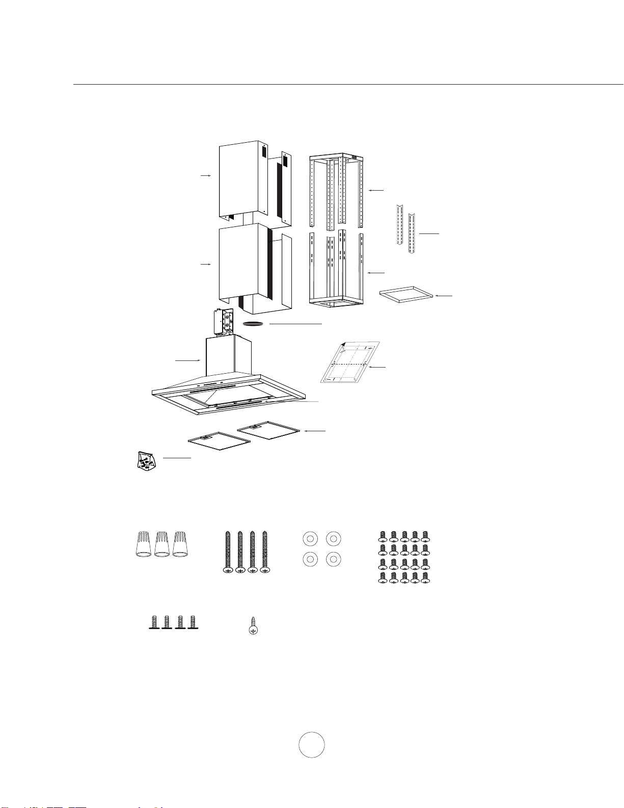
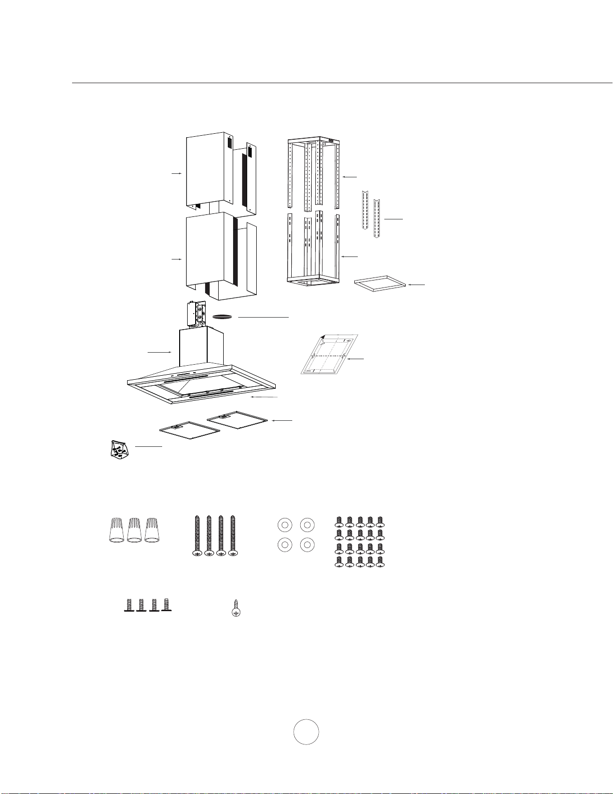
(3) Wire Nuts
(4) ø12 OD / ø5
ID Washers
(4) M4 x 1”
wood srews
(4) 3/16 x 1/4” pan-head
machine screws
(1) Hardware package
(1) 6” round damper (pre-installed)
PARTS SUPPLIED
HARDWARE PACKAGE CONTENTS
PARTS NOT SUPPLIED
- Ducting, conduit and all installation tools
- Cable connector (if required by local codes)
- Duct cover extension accessory
- Recirculating kit accessory
(2) Top Duct Covers
(1) Top Support Frame
(2) Bottom Duct Covers
(1) Bottom Support Frame
(1) Hood Body
(2) Brite Strip™ LED
(2) Mesh Filters
(ZAZ-E42 & ZRM-E42 x 3)
(1) M4 x 12
safety screw
A
B
Front of Hood
C
L
/
Cut-Out Shaded Area
(1) Paper ceiling template
(20) M4 x 8 pan-head
machine screws
(ZLC x 8)
(2) Lateral support brackets
(ZLC ONLY)
(1) Square support bracket
(ZAZ ONLY)
List of Materials
5
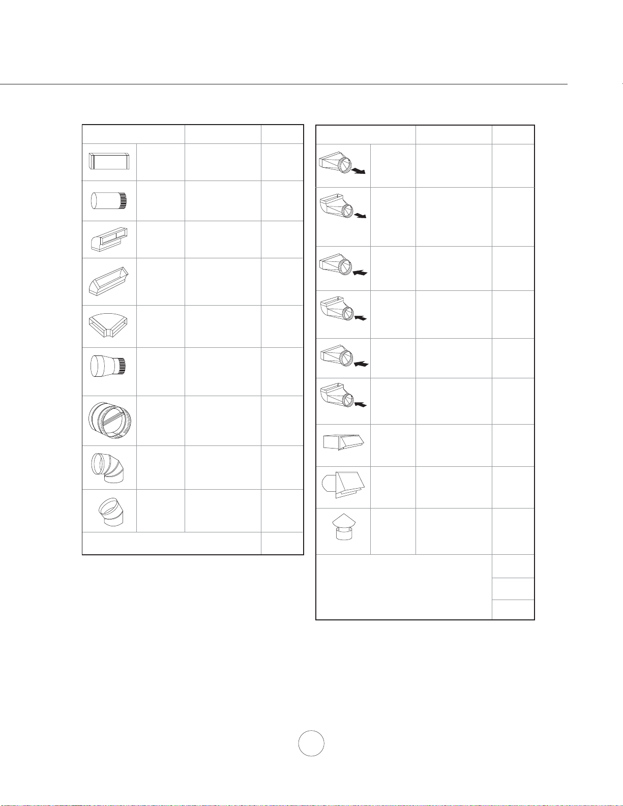
Duct pieces
Tot a l
Equivalent number
length x used =
3- 1/4” x 10”
Rect.,
straight
1 Ft. x ( ) =
Ft.
3- 1/4” x 10”
Rect. to
6” round
transition
5 Ft. x ( ) =
Ft.
3- 1/4” x 10”
Rect. to
6” round
transition
90
0
elbow
20 Ft. x ( ) =
Ft.
6”, 7”, 8”, 10”
Round,
90
0
15 Ft.
x ( ) =
Ft.
6”, 7”, 8”, 10”
Round,
45
0
9 Ft. x ( ) =
Ft.
Ft.
6”, 7”, 8”, 10”
Round,
straight
1 Ft. x ( ) =
Ft.
Subtotal column 1 =
Duct pieces
Tot a l
Equivalent number
length x used =
6”, 7”, 8”, 10”
Round, wall
cap with
damper
30 Ft. x ( ) =
Ft.
Ft.
Ft.
Ft.
6”, 7”, 8”, 10”
Round
roof cap
30 Ft. x ( ) =
Ft.
Subtotal column 2 =
Subtotal column 1 =
Total ductwork =
Maximum Duct Length: For satisfactory air movement,
the total duct length
should not exceed 100 equivalent feet.
6” round to
3- 1/4” x 10”
rect.
transition
1 Ft. x ( ) =
Ft.
6” round to
3- 1/4” x 10”
rect.
transition
90
0
elbow
16 Ft. x ( ) =
Ft.
7” round to
3 1/4” x 10”
rect.
transition
8 Ft. x ( ) =
Ft.
7” round to
3- 1/4” x 10”
rect.
transition
90
0
elbow
23 Ft. x ( ) =
Ft.
elbow
elbow
7” to 6” or
8” to 7” Round
tapered
reducer
25 Ft. x ( ) =
Ft.
3- 1/4” x 10”
Rect. 90
0
elbow
15 Ft. x ( ) =
Ft.
3- 1/4” x 10”
Rect. 45
0
elbow
9 Ft. x ( ) =
Ft.
3- 1/4” x 10”
Rect. 90
0
flat elbow
24 Ft. x ( ) =
Ft.
3- 1/4” x 10”
Rect.
wall cap
with damper
30 Ft. x ( ) =
Ft.
Ft. x ( ) =
Ft.
15
6”, 7“, 8”
Round
in-line
damper
Installation – Ducting Calculation Sheet
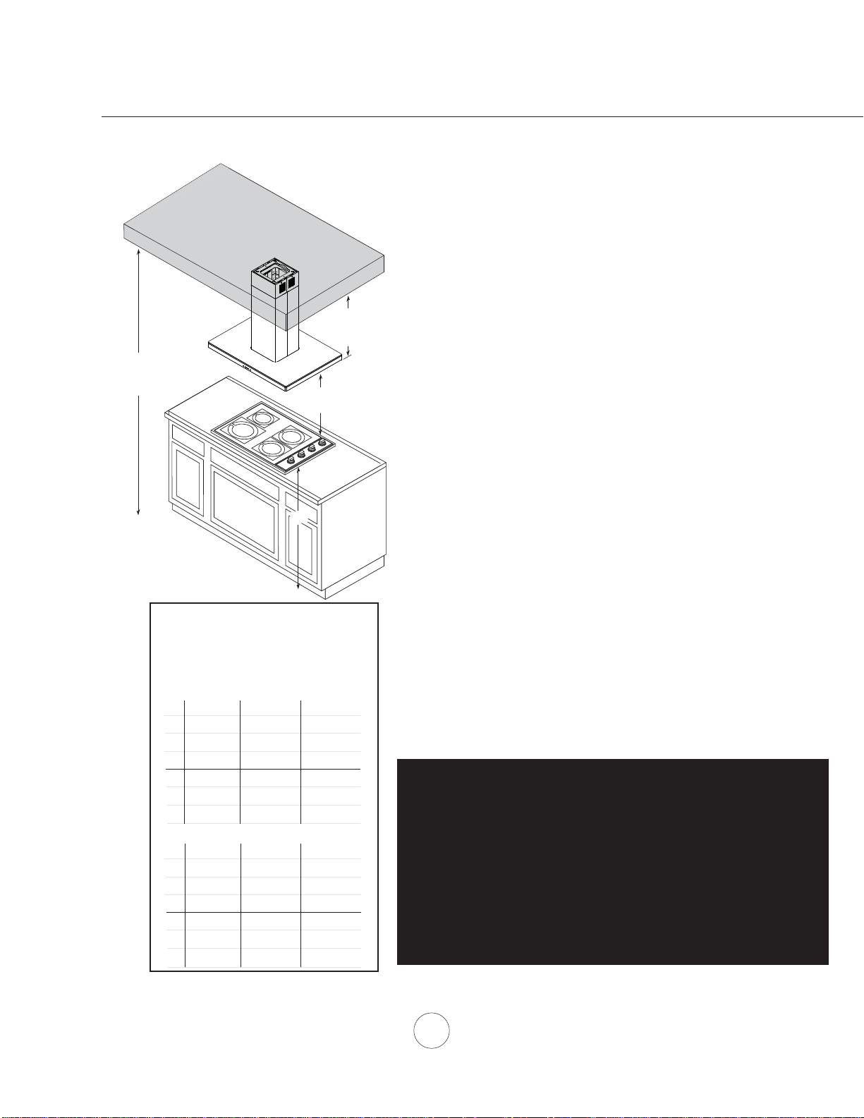
Installation – Mounting Height & Clearance
6
www.zephyronline.com
DUCTING
A minimum of 6” round duct is recommended to
PDLQWDLQPD[LPXPDLUÀRZHI¿FLHQF\
Always use rigid type metal ducts only. Flexible
GXFWVFRXOGUHVWULFWDLUÀRZE\XSWR
Use calculation worksheet to compute total duct
ZRUN3DJH
ALWAYS, when possible, reduce the number of
transitions and turns. If a long duct run is required,
increase duct size from 6” to 7” or 8”.
If turns or transitions are required: Install as far
away from duct opening and as far apart between
the two transitions as possible.
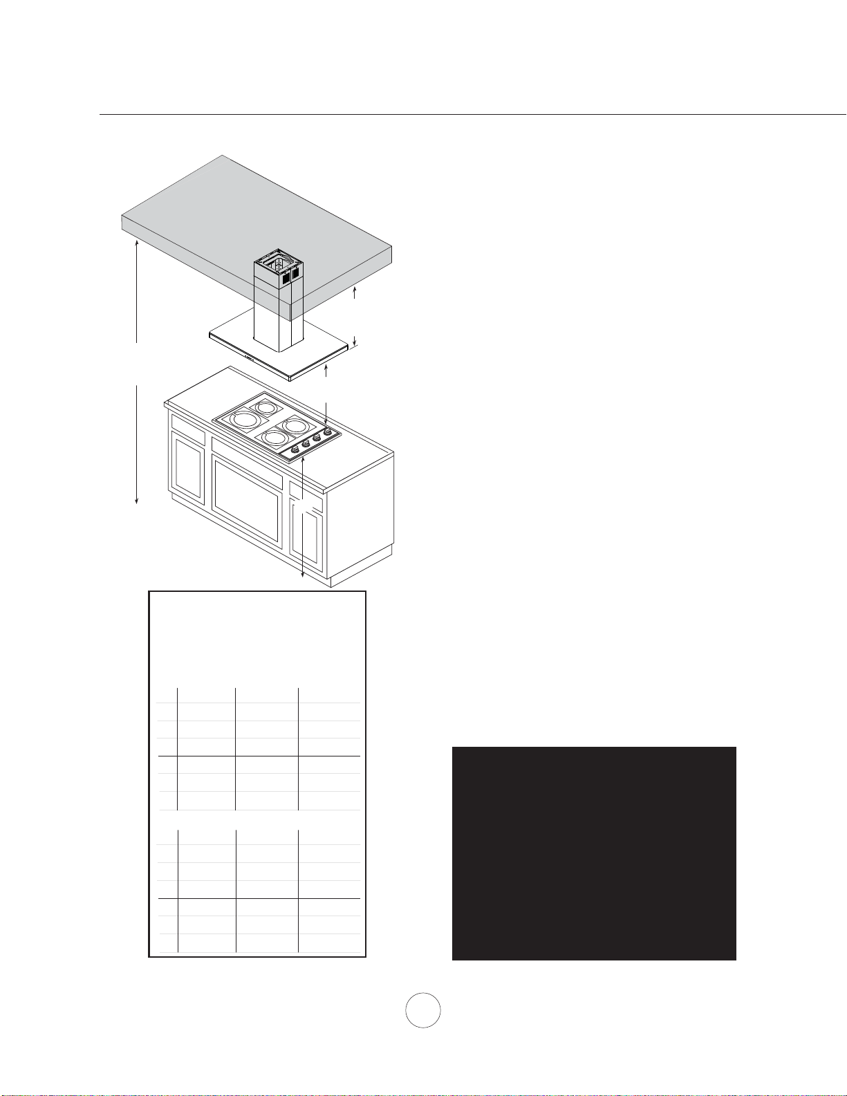
Minimum mount height between range top to hood
bottom should be no less than 26”.
Maximum mount height should be no higher than
34”.
It is important to install the hood at the proper
mounting height. Hoods mounted too low could
UHVXOWLQKHDWGDPDJHDQG¿UHKD]DUGZKLOHKRRGV
mounted too high will be hard to reach and will
ORRVHSHUIRUPDQFHDQGHI¿FLHQF\
If available, also refer to range manufacturer’s
height clearance requirements and recommended
hood mounting height above range. Always check
your local codes for any differences.
Duct cover extension kit available for ceiling
heights up to 12 feet. Turn to page 22 for part
number and ordering information.
DAMAGE-SHIPMENT / INSTALLATION:
3OHDVHIXOO\LQVSHFWXQLWIRUGDPDJHEHIRUH
installation.
,IWKHXQLWLVGDPDJHGLQVKLSPHQWUHWXUQWKH
unit to the store in which it was bought for
repair or replacement.
,IWKHXQLWLVGDPDJHGE\WKHFXVWRPHUUHSDLU
or replacement is the responsibility of the
customer.
,IWKHXQLWLVGDPDJHGE\WKHLQVWDOOHULIRWKHU
WKDQWKHFXVWRPHUUHSDLURIUHSODFHPHQWPXVW
be made by arrangement between customer
and installer.
A
B
C
D
E
F
ZAZ ZLC ZRM
Standard Duct Cover
Extension Duct Cover
A
B
C
D
E
F
ZAZ ZLC ZRM
28”
31”
39”
90” (7’ 6”)
80”
150” (12’ 6”)
28”
90” (7’ 6”)
47”
51”
80”
150” (12’ 6”)
109” (9’ 1”)
113” (9’ 5”)
36”
50”
98” (8’ 2”)
120” (10’)
47”
51”
80”
109” (9’ 1”)
113” (9’ 5”)
150” (12’ 6”)
A : Minimum Ducted Hood Height
B : Minimum Recirculating Hood Height
C : Maximum Hood Height
D : Minimum Ducted Ceiling Height
E : Minimum Recirculating Ceiling Height
F : Maximum Ceiling Height
min. A
min. B
max. C
36”
26” min.
34” max.
min. D
min. E
max. F
31-1/2”
93-
1/2
” (7’ 9-
1/2
”)
32-1/2”
46-
1/2”
94-
1/2
” (7’ 10-
1/2
”)
116-
1/2
” (9’ 8-
1/2
”)
93” (7’ 9”)
109” (9’ 1”)
50-
1/2”
50-
1/2”
112-
1/2
” (9’ 4-
1/2
”)
112-
1/2
” (9’ 4-
1/2
”)
7
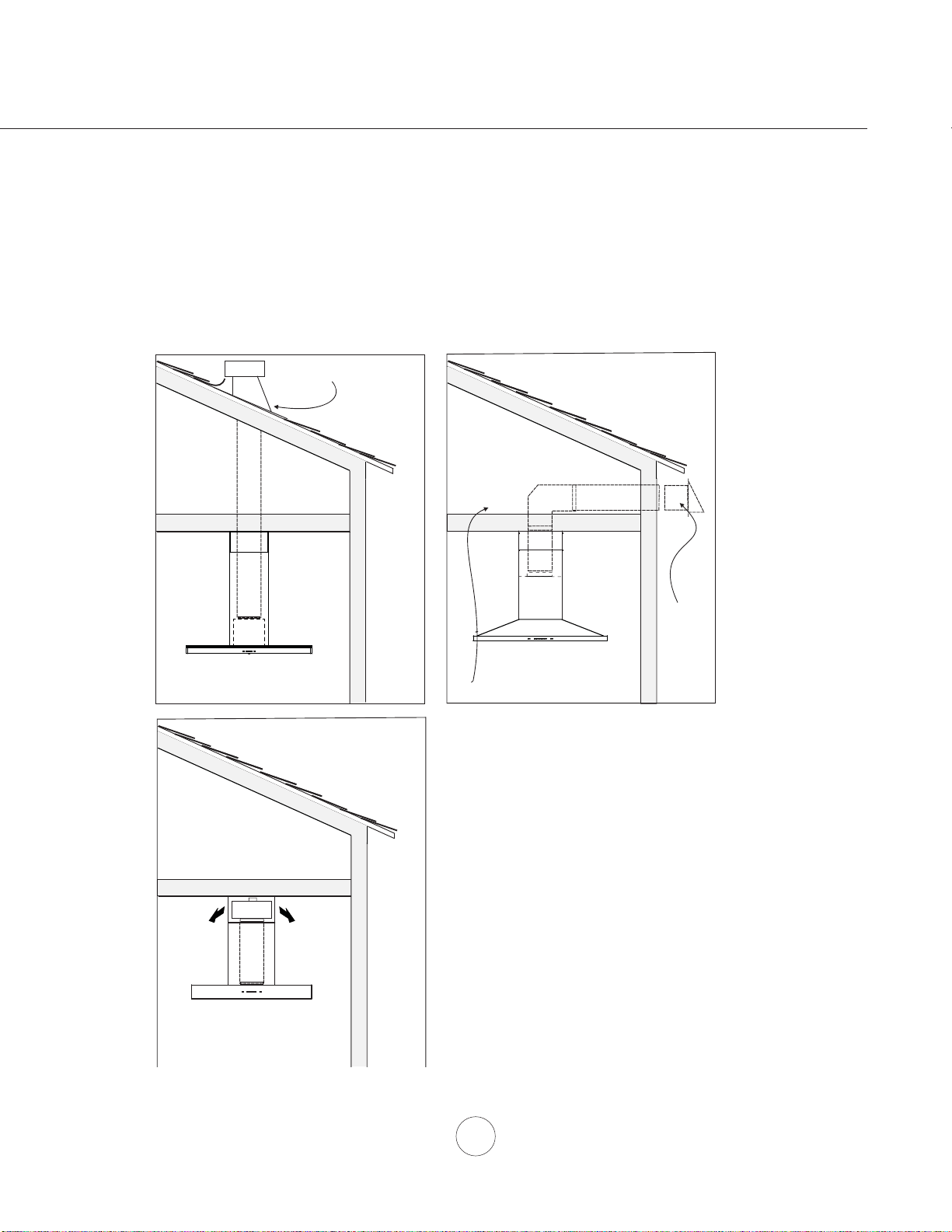
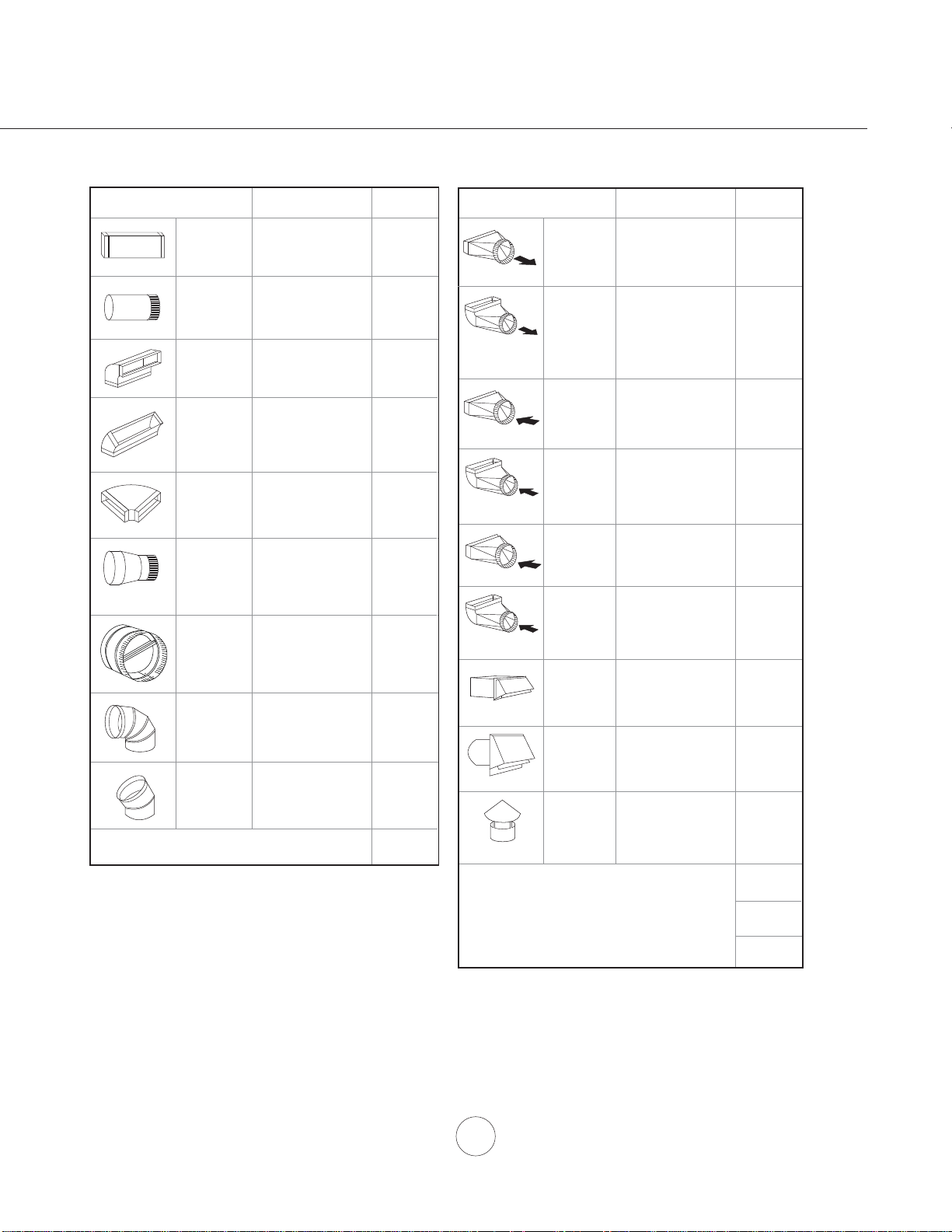
WARNING FIRE HAZARD
NEVER exhaust air or terminate duct work into spaces between walls, crawl spaces, ceiling, attics or garages.
All exhaust must be ducted to the outside, unless using the recirculating option.
Use single wall rigid metal ductwork only.
)DVWHQDOOFRQQHFWLRQVZLWKVKHHWPHWDOVFUHZVDQGWDSHDOOMRLQWVZFHUWL¿HG6LOYHU7DSHRU'XFW7DSH
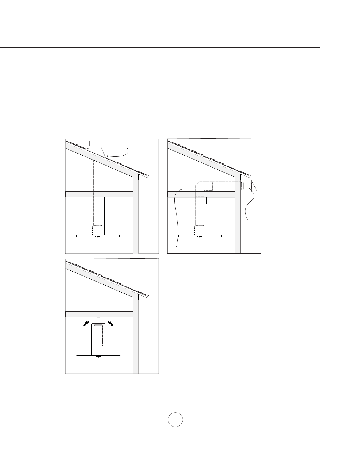
Some Ducting Options
Installation – Ducting Options
Roof Pitch w/
Flashing & Cap
ductless
recirculating
side wall cap
w/ gravity damper
Soffit or crawl space
(blower
housing)
8
www.zephyronline.com
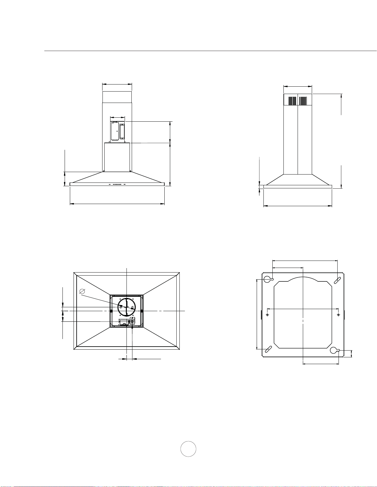
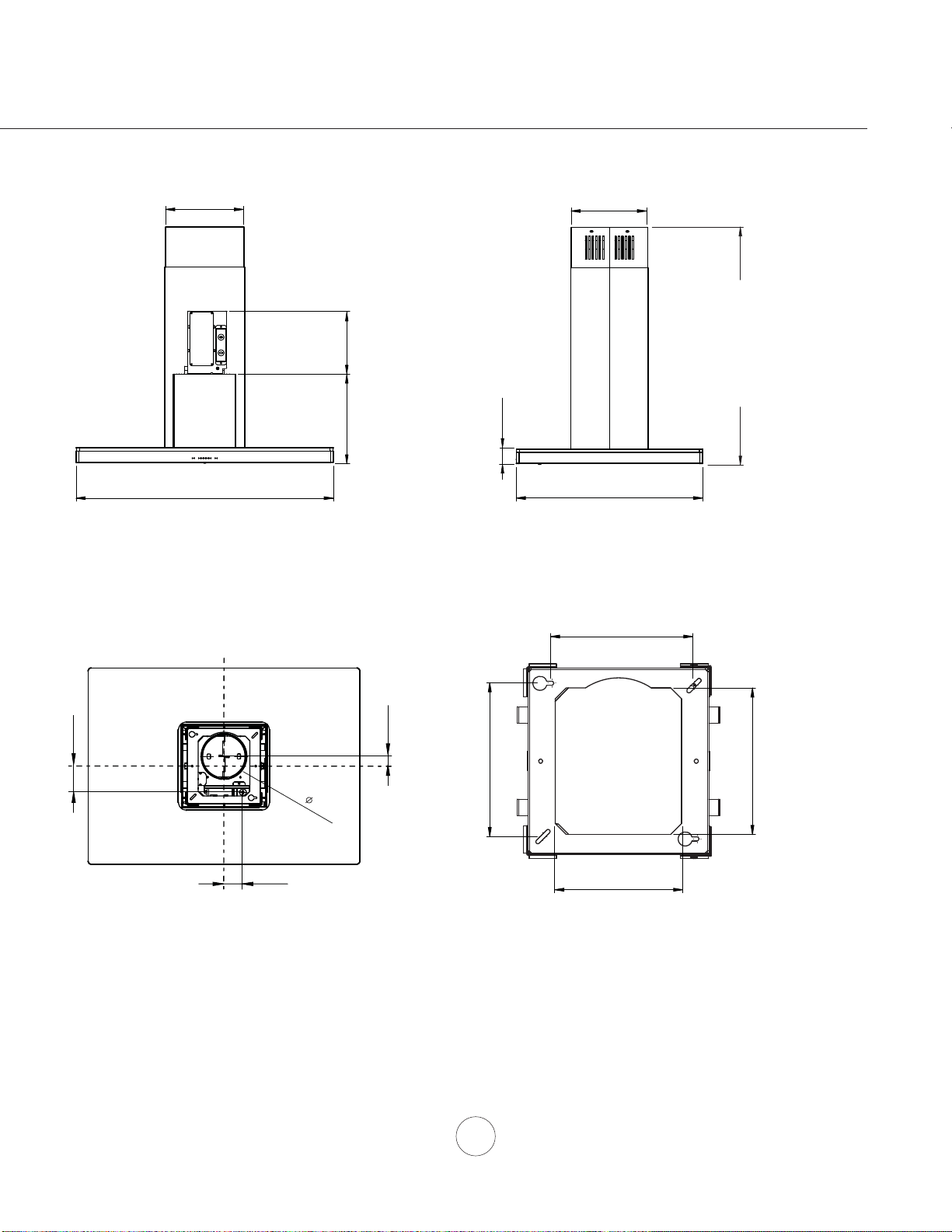
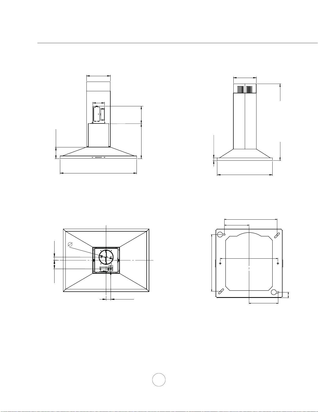
Installation – +RRG6SHFL¿FDWLRQ=$=
FRONT
SIDE
TOP of HOOD
TOP SUPPORT FRAME
(top view)
C/L
8 1/8”
7 9/16”
3 9/16”
13/16”
4 3/16”
8 1/4”
STANDARD
min. ducted - 31 1/2”
min. recirc. - 36”
max. - 50”
Z1C-00AZ
min. ducted - 47”
min. recirc. - 51”
max. - 80”
10 5/8”
25 9/16”
1 3/16”
11”
35 7/16”, 41 15/16”
9 7/16”
16 9/16”
5 1/4”
5 15/16”
3 1/2”
AC In
1 1/4”
C/L
C/L
1 7/8”
5 5/16”
9
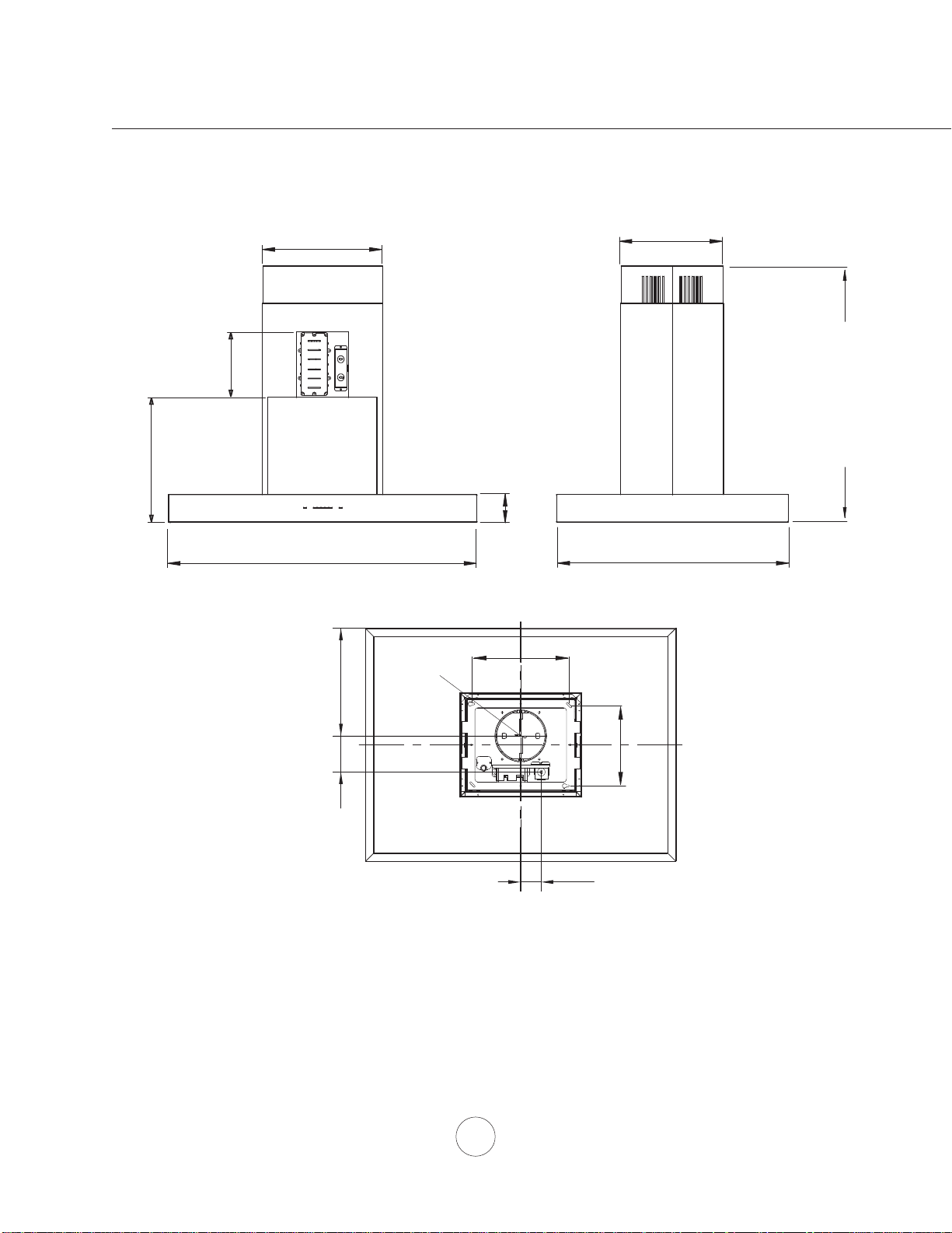
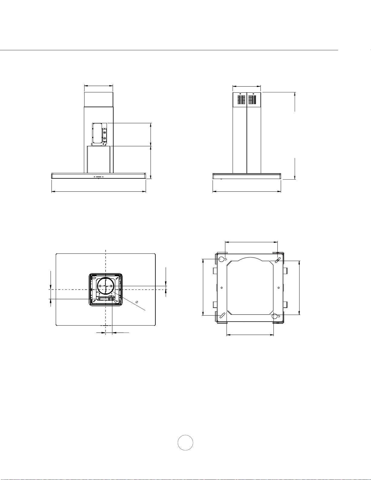
Installation – +RRG6SHFL¿FDWLRQ=/&
FRONT
SIDE
TOP of HOOD
TOP SUPPORT FRAME
(top view)
FRONT
11”
35 7/16”, 41 7/8”
9 7/16”
12
3/8”
25 9/16”
10 5/8”
STANDARD
min. ducted - 28”
min. recirc. - 32
1/2”
max. - 46
1/2”
Z1C-00LC
min. ducted - 47”
min. recirc. - 51”
max. - 80”
6”
2 1/2”
1 1/4”
3 7/16”
C/L
C/L
7 9/16”
6
3/4”
8 1/8”
7
13/16”
9 7/16”
2
1/16”
10
www.zephyronline.com
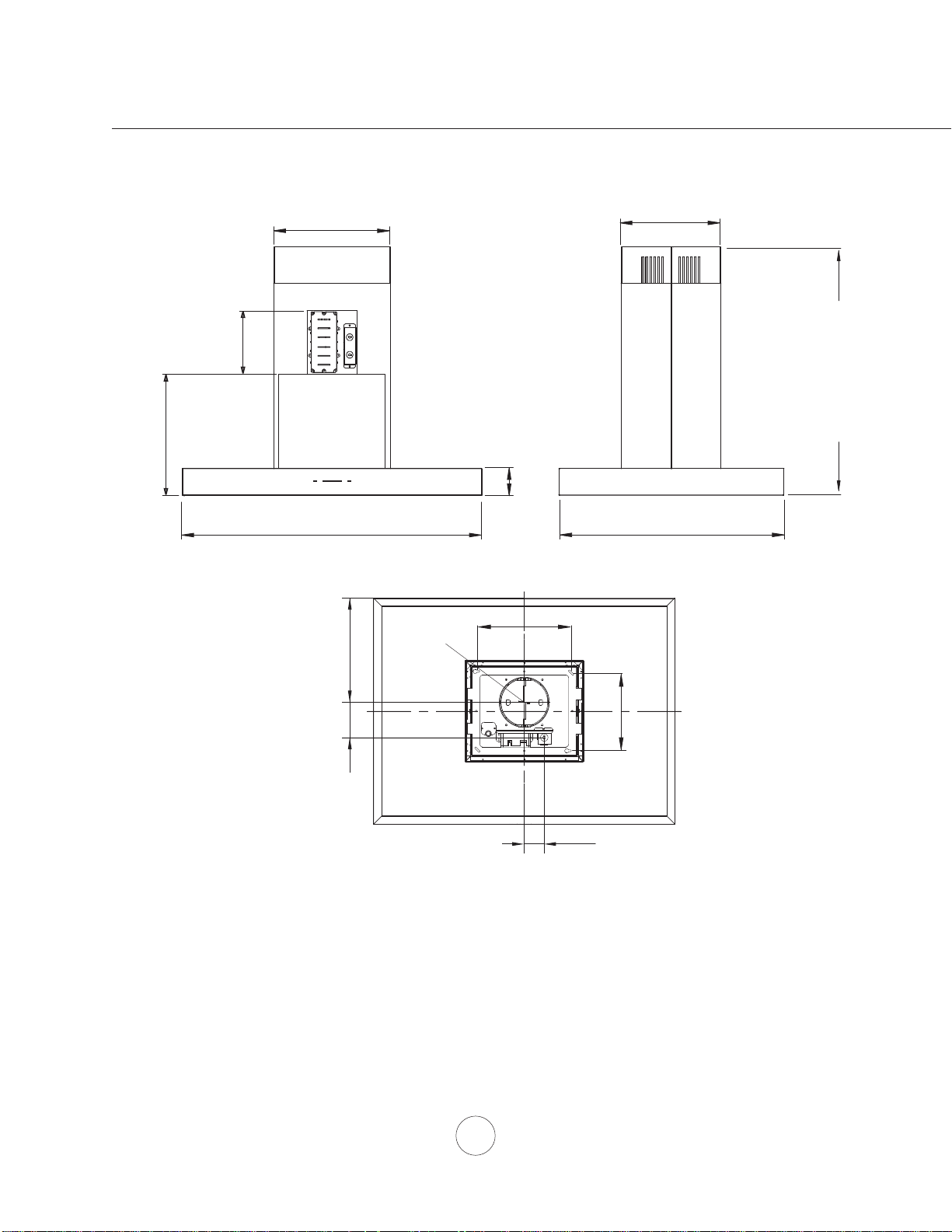
Installation – +RRG6SHFL¿FDWLRQ=50
35 7/8”, 41 7/8”
14”
3”
26 7/8”
STANDARD
min. ducted - 28”
min. recirc. - 31”
max. - 39”
Z1C-01RM EXTENSION
min. ducted - 50 1/2”
min. recirc. - 50 1/2”
max. - 80”
12”
11 3/16”
9 11/16”
AC-IN
2
CL
3/8"
4 3/16"12
7/16
"
ø 6"
11"
9 7/16"
11
1
2
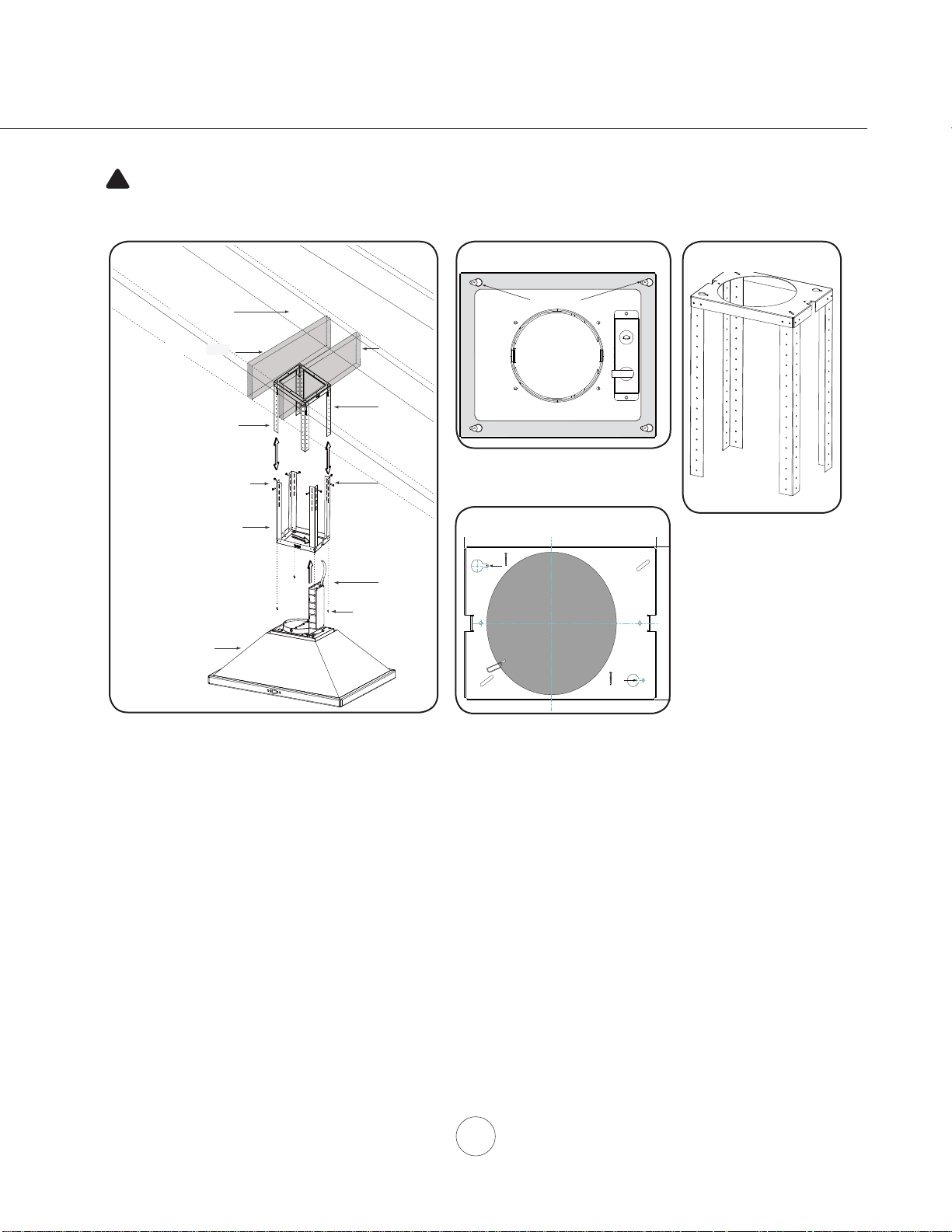
Ceiling Joists
Wood Blocking
Top Support Frame
Support Frame Arm
Bottom Support Frame
Hood Body
3
Mounting Screws
(pre-installed)
4
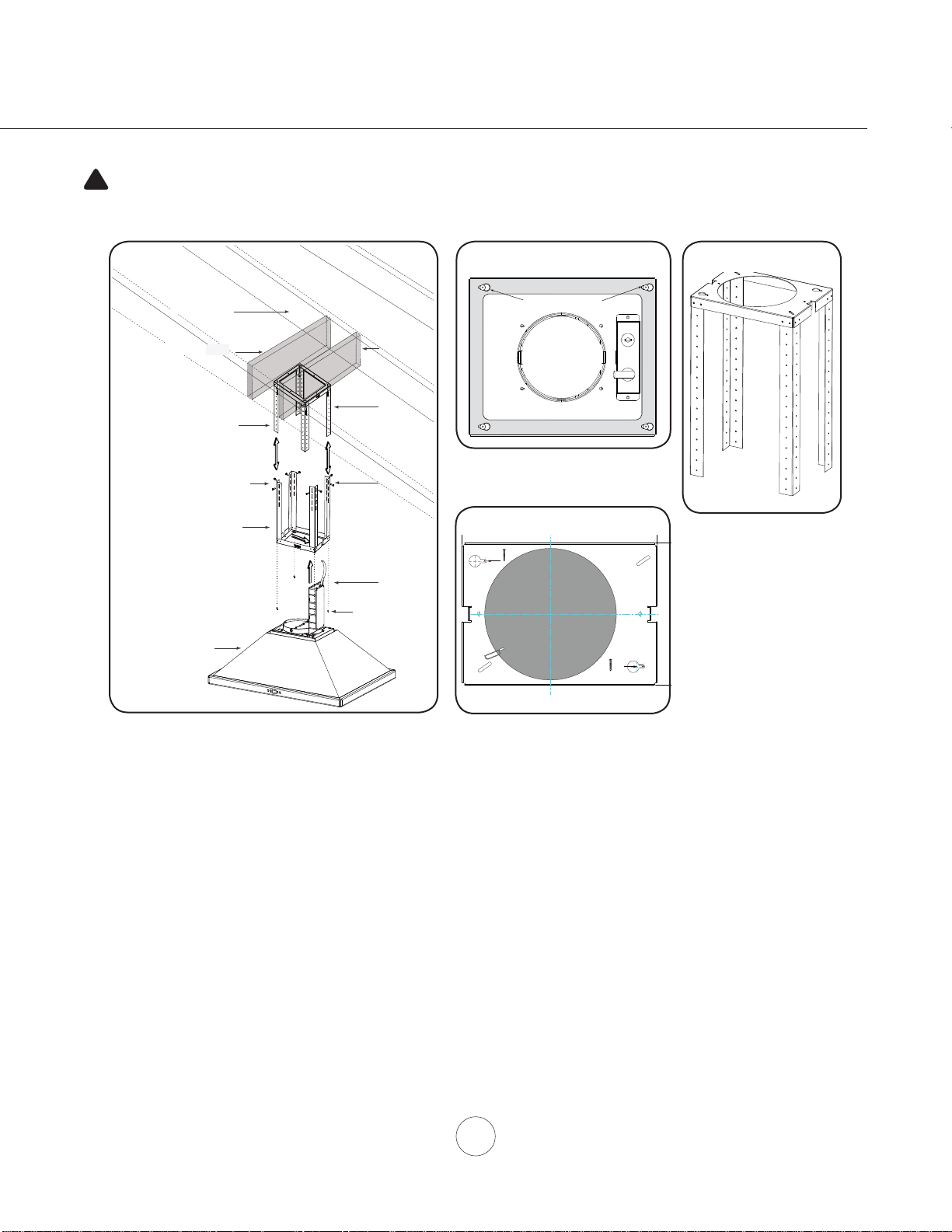
Installation – Mounting the Hood
'HWHUPLQHPRXQWLQJORFDWLRQRQFHLOLQJDQGWHPSRUDULO\WDSHSDSHUWHPSODWHLQFOXGHGZLWKWKHKRRGWR
the ceiling. Cut out internal shaded area of template to allow the ducting and electrical to pass through.
,IQHFHVVDU\DGGZRRGEORFNLQJPLQ´[´WRFHLOLQJMRLVWVORFDWHGEHKLQGWKHGU\ZDOOWRUHLQIRUFHWKH
PRXQWLQJORFDWLRQ),*$6HFXUH0[´ZRRGVFUHZVWRSRLQWV$DQG%RIWKHSDSHUWHPSODWH),*
*'RQRWFRPSOHWHO\WLJKWHQVFUHZVOHDYHDSSUR[´H[SRVHG
2. Remove screws securing top and bottom support frames together. Adjust support frame to accomodate the
GHVLUHGKRRGKHLJKWDQGUHDVVHPEOHWKHIUDPHXVLQJWKHSUHYLRXVO\UHPRYHGVFUHZVVFUHZVIRUHDFK
VXSSRUWIUDPHDUP),*$
3. Lift support frame assembly up to the ceiling making sure the word “front” on the top support frame faces the
IURQWRIWKHKRRGZKHUHWKHFRQWUROVZLOOEHORFDWHG),*%7KHNH\KROHVRQWKHWRSVXSSRUWIUDPHVKRXOG
cover the wood screws previously installed in the ceiling. Slide support frame towards narrow end of key
KROHVWRORFNWKHIUDPHLQSODFH,QVWDOOWKHODVW0[´ZRRGVFUHZVZLWKZDVKHUVLQWRWKHWZRUHPDLQLQJ
corners of the top support frame to secure it to the ceiling. Tighten all screws.
/LIWKRRGDQGDOLJQWKHSUHLQVWDOOHGPRXQWLQJVFUHZVORFDWHGRQWRSRIWKHXQLWERG\),*$ZLWKWKH
NH\KROHVRQWKH%RWWRPRI6XSSRUW)UDPH),*&6OLGHKRRGWRZDUGVWKHQDUURZHQGRINH\KROHVWRORFN
LQWRSODFH+DQGWLJKWHQHDFKRIWKHVFUHZVZLWKDVFUHZGULYHUWRVHFXUHKRRGWR%RWWRP6XSSRUW)UDPH
)XUWKHUVHFXUHERWWRPVXSSRUWIUDPHWRXQLWERG\E\RQH0[VDIHW\VFUHZ),*)SJ
+RRGLVLQWHQGHGWREHPRXQWHGWRD¿QLVKHGFHLOLQJ
CAUTION: At least two installers are
required due to the weight and size of the
hood.
!
Bottom Support Frame
(secures to top of blower housing)
Key Holes
front - facing controls
back
FIG. A
FIG. C
FIG. B
Side
Front
XP022220
A
B
Cut-Out Shaded Area
FIG. G
FRONT
12
www.zephyronline.com
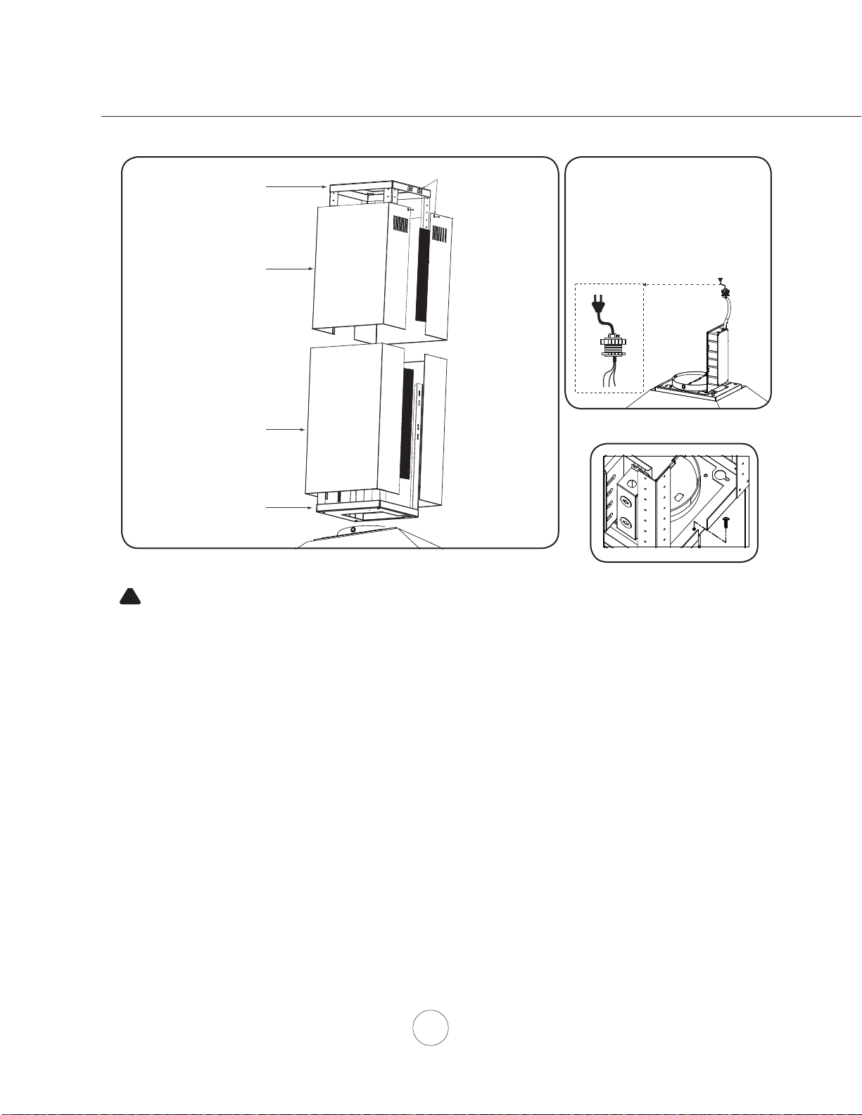
Installation – Mounting the Hood
1
Top Duct Covers
Top Support Frame
Bottom Duct Covers
Bottom Support Frame
5. Remove tape securing electronics mounting bracket to hood and reposition electronics mounting bracket.
),*(,QVWDOOHOHFWULFDODQGGXFWZRUN$FDEOHORFNQRWVXSSOLHGPLJKWEHUHTXLUHGE\ORFDOFRGHV),*
(6HDOGXFWZRUNZLWKDOXPLQXPGXFWWDSH
6. Power up hood, verify all functions and check for leaks around duct tape.
$VVHPEOH7RS'XFW&RYHUVZLWKORXYHUKROHVWRJHWKHURYHU7RS6XSSRUW)UDPHVHFXUH7RS'XFW&RYHUV
together by magnetic strips. Note: If using hood in ductless recirculating mode you must install the air
diverter plate to the Top Support Frame prior to assembling the duct covers. Turn to page 11 for more
details.
6HFXUH7RS'XFW&RYHUVWR7RS6XSSRUW)UDPHE\XVLQJ[VFUHZVVFUHZVIRUHDFK7RS'XFW
&RYHU),*'
9. Assemble Bottom Duct Covers together over Top Duct Covers and secure together by magnetic strips.
Bottom Duct Covers should rest on top of the Hood Body.
FIG. D
Cable Lock
Cable Lock
$ FDEOH ORFNLQJ FRQQHFWRU QRW
VXSSOLHG PLJKW EH UHTXLUHG
by local codes. Check with
local requirements and codes,
purchase and install appropriate
connector if necessary.
FIG. E
WARNING: Electrical wiring must be done by a qualified person(s) in
accordance with all applicable codes and standards. This range hood must be
properly
grounded. Turn off electrical power at service entrance before wiring.
!
FIG. F

13
Ductless recirculation is intended for applications where an exhaust duct work is not possible to be installed.
When converted, the hood functions as a recirculating hood rather than an exhaust hood. Fumes and exhaust
IURPFRRNLQJDUHGUDZQDQG¿OWHUHGE\DVHWRIRSWLRQDOFKDUFRDO¿OWHUV7KHDLULVWKHQSXUL¿HGDQGUH
circulated back within the home.
We recommend to ALWAYS exhaust air outside of the home by employing existing or installing new duct
ZRUNLISRVVLEOH7KHKRRGLVPRVWHIIHFWLYHDQGHI¿FLHQWDVDQH[KDXVWKRRG2QO\ZKHQWKHH[KDXVWRSWLRQ
is not possible should you recourse to converting the hood into a recirculating hood.
:KHQFRQYHUWHGWREHDUHFLUFXODWLQJKRRGDVHWRIFKDUFRDO¿OWHUVDUHUHTXLUHGRQWRSRILWVVWDQGDUG
DOXPLQXPPHVK¿OWHUVHW2UGHUDFFRUGLQJWRLWVSDUWQXPEHUEHORZ7KHVWDQGDUGDOXPLQXPPHVK¿OWHUVDUH
LQWHQGHGWRFDSWXUHUHVLGXHIURPFRRNLQJDQGWKHRSWLRQDOFKDUFRDO¿OWHUVKHOSWRSXULI\IXPHVH[KDXVWHGIURP
cooking for recirculation.
RECIRCULATING KIT (REQUIRED IF NO DUCTING IS USED)
.LWLQFOXGHVFKDUFRDO¿OWHU¿OWHUDWWDFKPHQWFOLSDQGDLUGLYHUWHUSODWH
Hood Models Part No. Filters in pkg.
ZAZ ZRC-02AZ 2
ZLC ZRC-00LC 1
ZRM-E36DS ZRC-02RM 2
ZRM-E42DS ZRC-01RM 3
1. Purchase recirculating kit per the part number above
2. Secure air diverter plate to top support frame. Open sides of air diverter plate should face left and right
to direct air through the louver holes located on the top duct cover. Run 6” ducting from top of hood and
secure to air diverter plate.
5HPRYHPHVK¿OWHUVIURPKRRG,QVWDOOFKDUFRDO¿OWHUVDVUHIHUHQFHGZLWKWKHPDQXDOLQFOXGHGZLWK
recirculation kit.
5H,QVWDOOPHVK¿OWHUV
7XUQRQFKDUFRDO¿OWHUFKDQJHLQGLFDWRURQFRQWUROSDQHO5HIHUWRGHWDLOVRQSDJH7KH
PLFURSURFHVVRULQWKHFRQWUROVZLOOLQGLFDWHWKHQHHGWRFKDQJHWKHFKDUFRDO¿OWHUDIWHUKRXUVRI
FRQWLQXRXVXVH2UGHUUHSODFHPHQWFKDUFRDO¿OWHUVSHUWKHOLVWEHORZ
&KDUFRDO¿OWHUVPXVWEHUHSODFHGDIWHUHYHU\KRXUVRIXVHRUDSSUR[LPDWHO\HYHU\WRPRQWKV
EDVHGRQDQDYHUDJHRIKUVRIGDLO\FRRNLQJWLPH
NOTE: For more details refer to manual included with recirculation kit.
Charcoal Filter Replacements
Hood Model Part No. Qty to Order
ZAZ Z0F-C091 2
ZLC Z0F-C092 1
ZRM-E36DS Z0F-C002 2
ZRM-E42DS Z0F-C002 3
'2127:$6+&+$5&2$/),/7(56&KDUFRDO¿OWHUVPD\QHHG
to be changed more often depending on cooking habits.
Installation – Ductless Recirculating
14
www.zephyronline.com
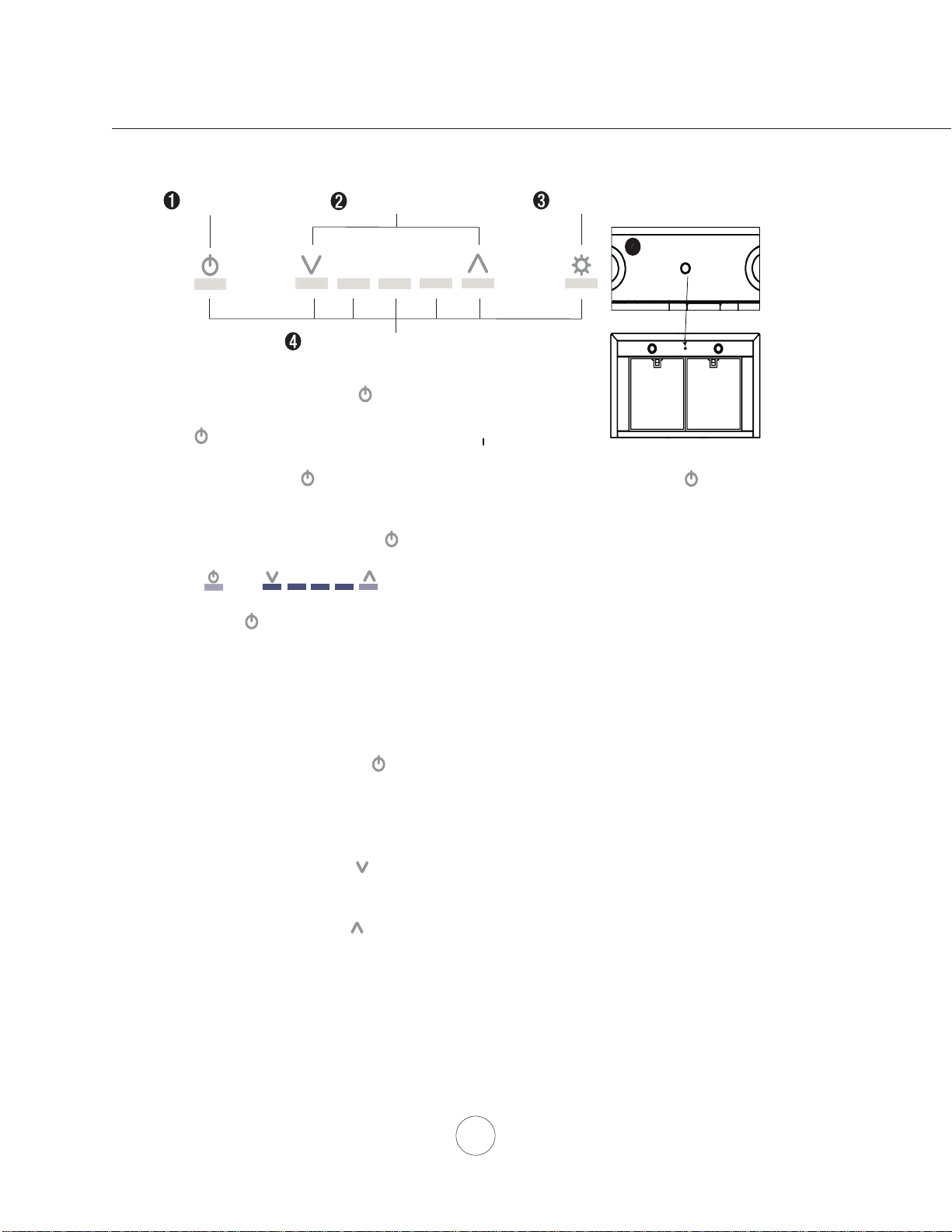
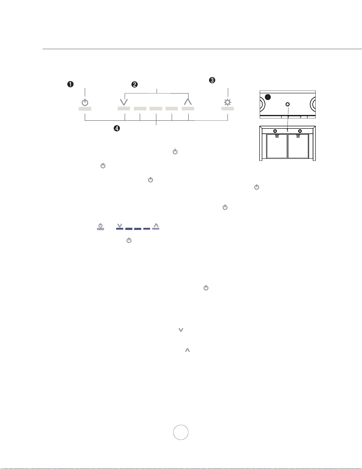
Lights On/Dim/Off
Display (speed level, delay off, filter clean/change)
Adjust 5 Speed Levels
Power / Delay Off
1 POWER / DELAY OFF BUTTON
Power Button Function
- Button will turn power on and off for entire hood (fan and lights).
- Hood will remember the last speed and light level it was turned off at.
(Example: Press Button to turn off hood when on fan speed 4 and high lights. Press Button
again and the hood will turn back on at speed 4 and high lights level.)
Delay Off Button Function
- With the fan on press and hold the Button for two seconds. The fan will change to speed 1 and the
5 minute delay off timer will start.
+ LEDs will illuminate and slowly blink in accordance with the time
remaining until the fan and lights automatically turn off.
- Pressing Button while Delay Off Function is enabled will turn the hood off and cancel the Delay Off
Function.
ACT Verification
- Airflow Control Technology (ACT) allows the installer to set the maximum fan CFM to align with local
codes and regulations.
- To verify the maximum fan CFM:
- With hood off, hold the Button for two seconds. If all five fan speed indicators illuminate =
default maximum CFM. If four fan speed indicators illuminate = 390 maximum CFM. If 3 fan
speed indicators illuminate = 290 maximum CFM.
2 SPEED SELECTION BUTTON
Fan Speed Decrease Button
- Press this button to decrease fan speed. 5, 4, 3, 2, 1.
- If fan is On Speed 1 and this button is pressed, fan will power Off.
Fan Speed Increase Button
- Press this button to increase fan speed. Fan On, 1, 2, 3, 4, 5.
- If hood is Off and this button is pressed, fan will turn On Speed 1.
Act Enabled Speed Selections
- When ACT is enabled, the number of fan speeds will be reduced as follows:
- 390 CFM = Maximum 4 speeds
- 290 CFM = Maximum 3 speeds
Lighted Glass Button
5
MODEL ZLC ONLY
Features & Controls - ICON Touch Controls
15
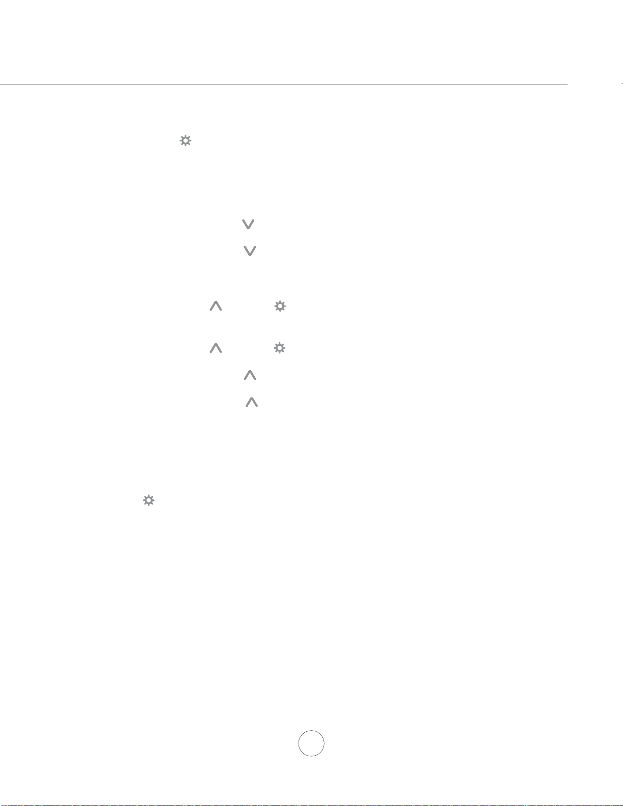
3 LIGHTS BUTTON
- Lights are two levels, High and Low.
- From off, press one time for High. Press again for Low. Press again to power lights off.
4 DISPLAY INDICATORS
Mesh Filter Clean Reminder (always enabled)
- After 30 hours of fan usage, the button indicator will begin to slowly blink indicating it is time to
clean the mesh filters.
- To reset: With hood off: hold the button for three seconds. All LED indicators will blink two times
confirming the 30 hour timer has been reset.
Charcoal Filter Replace Indicator (disabled by default, must be enabled if recirculating hood)
- To enable Charcoal Filter Replacement Reminder:
- With hood off, hold button and button simultaneously for two seconds. All LED indicators
will illuminate for three seconds confirming the Charcoal Filter Replace Reminder is enabled.
- To disable Charcoal Filter Replacement Reminder:
- With hood off, hold button and button simultaneously for two seconds. All LED indicators
will blink two times confirming the Charcoal Filter Replace Reminder is disabled.
- After 120 hours of fan usage the button will slowly blink indicating the charcoal filters need
replacment.
- To reset: With hood off, hold the button for two seconds. All LED indicators will blink two times
confirming the 120 hour timer has been reset.
5 LIGHTED GLASS BUTTON (MODEL ZLC ONLY)
- Press to cycle glass color from White, Blue, Amber and Off.
- Press and hold for 3 seconds to activate demo mode. While in demo mode each color will gradually
change every 10 seconds.
- Pressing to power off the LED lights will also power off the lighted glass.
Features & Controls - ICON Touch Controls
16
www.zephyronline.com
SURFACE MAINTENANCE:
Clean the hood surface periodically with hot soapy water and clean cotton cloth. Do not use corrosive or
abrasive detergent or steel wool/scouring pads which will scratch and damage surface.
For heavier soil use liquid degreaser.
After cleaning it is recommended that you use non-abrasive stainless steel polish/cleaners, to polish and
buff out the stainless luster and grain. Always scrub lightly, with clean cotton cloth, and with the grain.
Do not use any product containing chlorine bleach. Do not use “orange” cleaners.
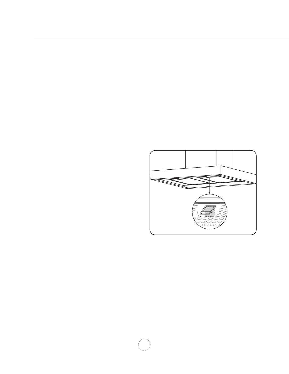
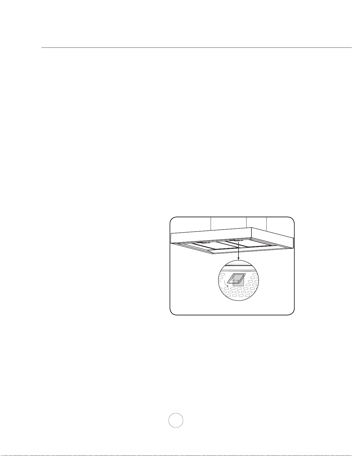
Aluminum Mesh Filters
7KHDOXPLQXPPHVK¿OWHUVLQVWDOOHGE\WKHIDFWRU\DUHLQWHQGHGWR¿OWHURXWUHVLGXHDQGJUHDVHIURP
cooking. They need not be replaced on a regular basis but are required to be kept clean.
Remove and clean by hand or in dishwasher on low heat. Spray degreasing detergent and leave to soak if
heavily soiled.
'U\¿OWHUVDQGUHLQVWDOOEHIRUHXVLQJKRRG
Removing Aluminum Mesh Filters
3XOOGRZQRQ¿OWHUODWFKWRGLVHQJDJH¿OWHUVSULQJ
3XOOGRZQRQ¿OWHUKDQGHWRUHPRYH¿OWHU
Maintenance – Hood and Filter Cleaning
17
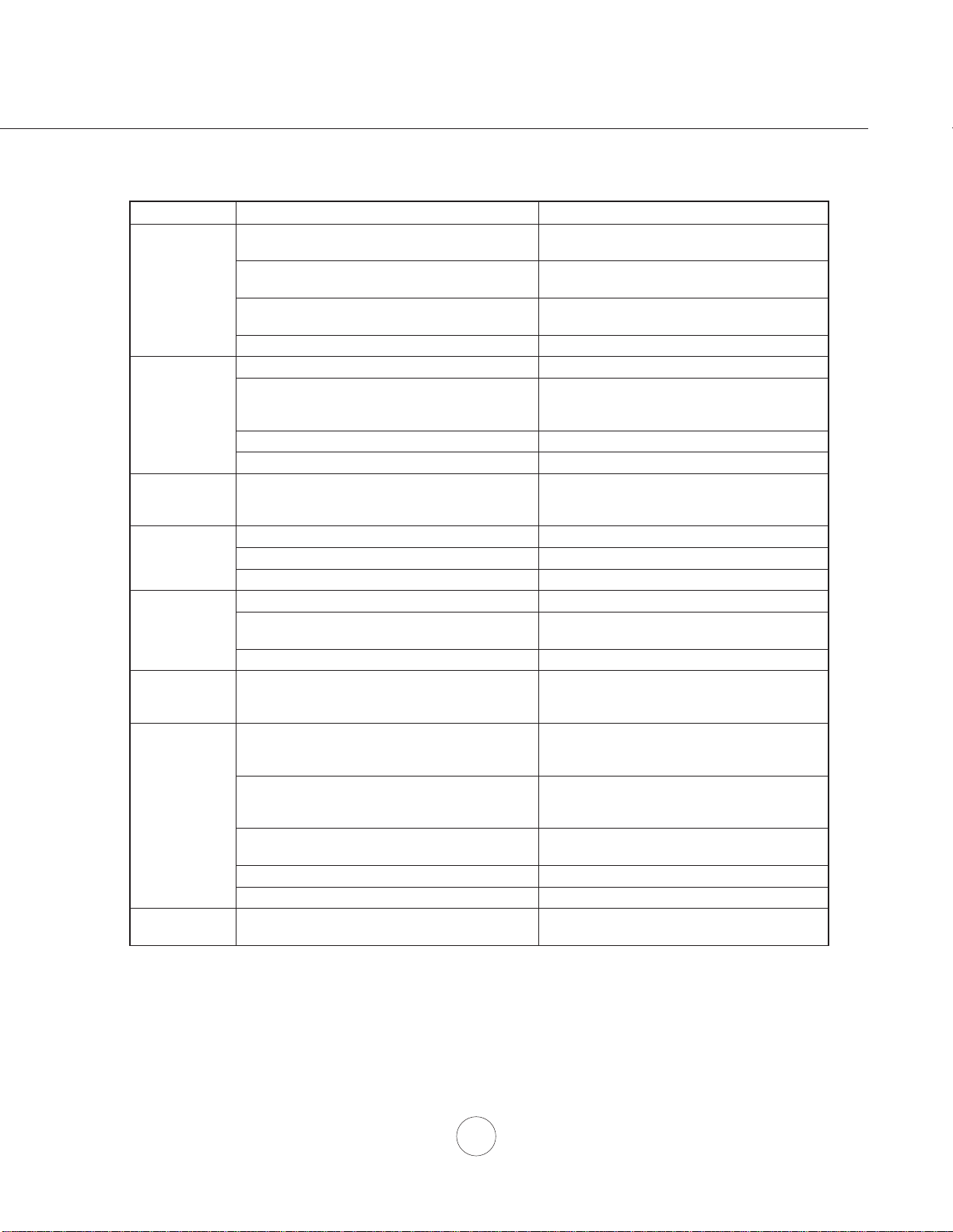
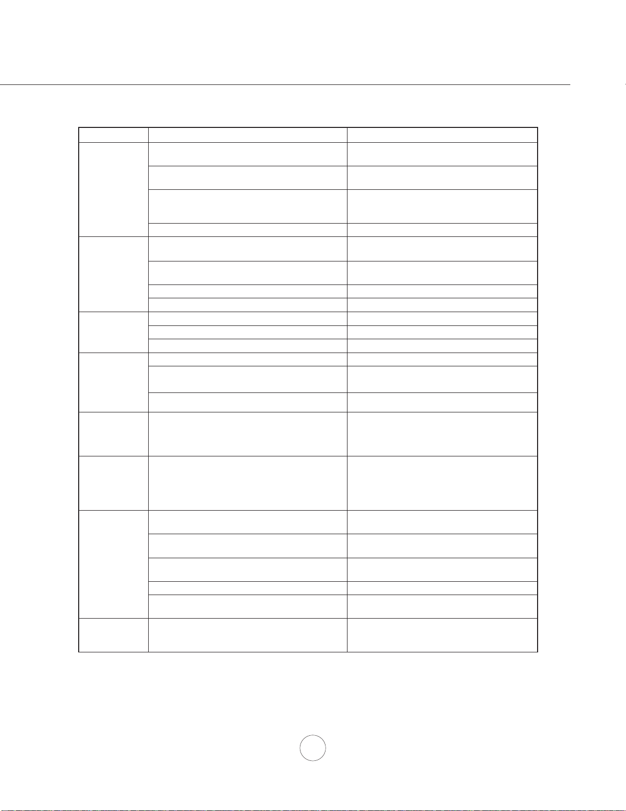
Troubleshooting
TROUBLESHOOTING PROCEDURES
Issue Cause What to do
After installation,
the unit doesn’t
work.
1. The power source is not turned ON. 1. Make sure the circuit breaker and the unit’s
power is ON.
2. The power line and the cable locking connector
is not connecting properly.
2. Check the power connection with the unit is
connected properly.
3. The switch board or control board wirings are
disconnected.
3. Make sure the wirings at the switch board and
control board are connected properly.
4. The switch board or control board is defective. 4. Change the switch board or control board.
Light works, but
blower is not
turning.
1. The blower is defective, possibly seized. 1. Change the blower.
2. The thermally protected system detects if the
blower is too hot to operate and shuts the blower
down.
2. The blower will function properly after the
thermally protected system cool down.
3. Damaged capacitor. 3. Change the capacitor.
4. The switch board or control board is defective. 4. Change defective part.
The speed levels
of the blower
sound the same.
1. Using the wrong size or type of ducting. 1. Change the duct size to at least 6” round or
higher and change the duct type to rigid metal
UDWKHUWKDQÀH[DEOH
The unit is
vibrating.
1. The blower is not secured in place. 1. Tighten the blower in place.
2. Damaged blower wheel. 2. Replace the blower.
3. The hood is not secured in place. 3. Check the installation of the hood.
The blower is
working, but the
lights are not.
1. Defective LED bulb. 1. Change the LED bulb.
2. The LED wire connection to the control board is
disconnected.
2. Check the LED wire connection at the control
board.
3. The LED bulb connector is disconnected. 3. Check the LED bulb connector.
The unit turns on
by itself.
1. A spot light or kitchen lamp is shining directly
onto the switch controls.
1. The switch controls are light sensative. A
direct light source onto the switch controls
may disrupt switch functions.
The hood is
not venting out
properly.
1. The hood might be hanging to high from the
cook top.
1. Adjust the distance between the cook top and
the bottom of the hood within 26” and 34”
range.
2. The wind from the opened windows or opened
doors in the surrounding area are affecting the
ventilation of the hood.
2. Close all the windows and doors to eliminate
WKHRXWVLGHZLQGÀRZ
3. Blockage in the duct opening or ductwork. 3. Remove all the blocking from the duct work or
duct opening.
4. The direction of duct opening is against the wind. 4. Adjust the duct opening direction.
5. Using the wrong size of ducting. 5. Change the ducting to at least 6” or higher.
Mesh Filter is
vibrating.
0HVK¿OWHULVORRVH &KDQJHWKHPHVK¿OWHU
18
www.zephyronline.com
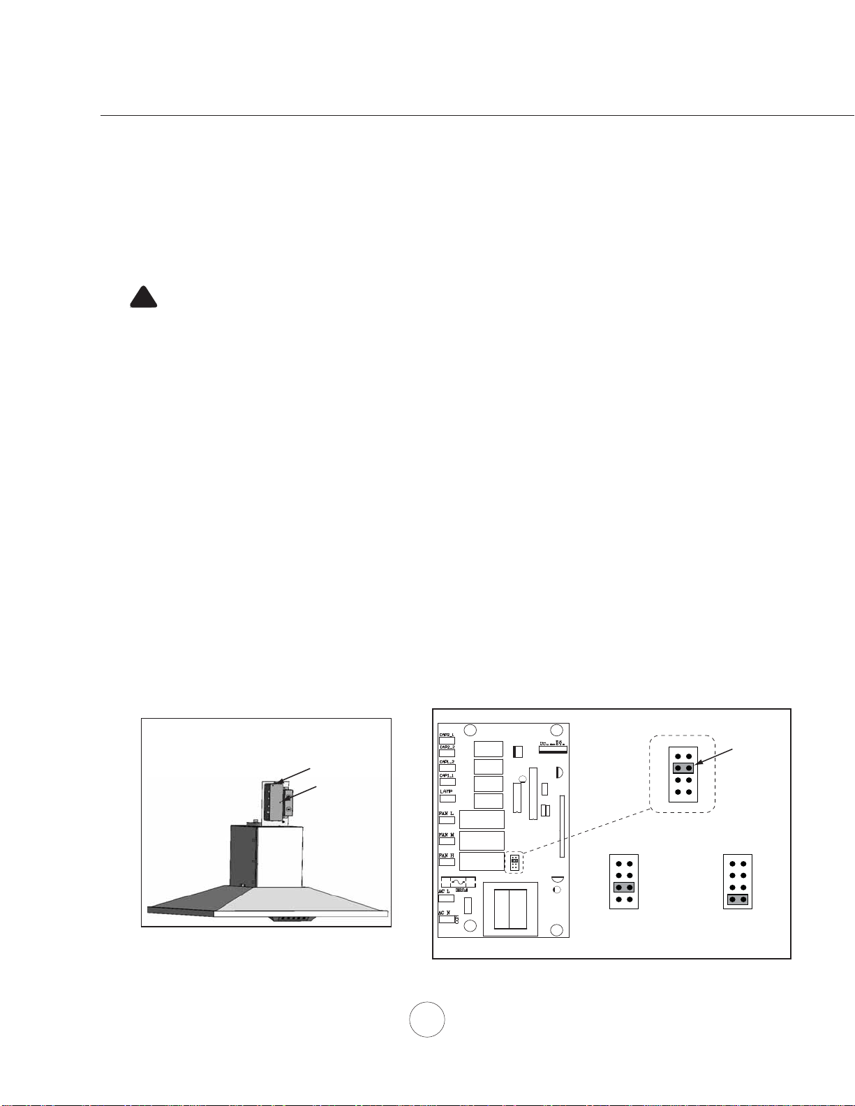
ACT Conversion
ALUÀRZ&RQWURO7HFKQRORJ\$&7
Some local codes limit the maximum amount of CFM a range hood can move. ACT allows you to control the
maximum blower CFM of select Zephyr Ventilation range hoods without the need for expensive make up air kits.
$&7HQDEOHVWKHLQVWDOOHUWRHDVLO\VHWWKHPD[LPXPEORZHUVSHHGWRRQHRIWZRPRVWFRPPRQO\VSHFL¿HG&)0
OHYHOVRU&)07KHXVDJHRI$&7PD\QRWEHQHFHVVDU\IRU\RXULQVWDOODWLRQ3OHDVHFKHFN\RXUORFDOFRGHV
for CFM restrictions.
By default the maximum blower CFM is set to 600.
To enable ACT
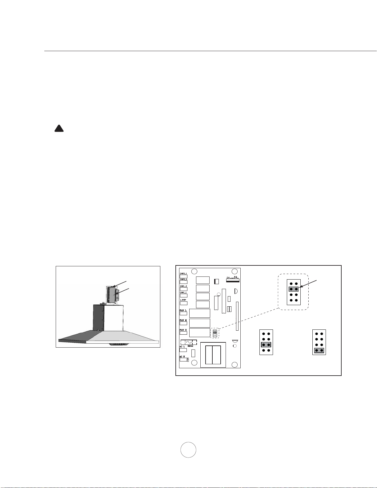
1. Before hood installation, gain access to PC board by following the steps shown in FIG. J.
2. Change plastic jumper positioning as shown in FIG. K to set the desired maximum blower CFM.
3. Re-install PC board & continue with hood installation.
4. Remove the appropriate foil CFM sticker included with the hood literature and place inside the hood body below
the wiring diagram or in another clearly visible location.
NOTE: After re-positioning the jumper and powering on the hood, the CFM cannot be changed again.
To verify if your installer enabled ACT
With hood off, press and hold the power button for three seconds. If 5 LEDs illuminate = defualt max. CFM, if 4 LEDs
illuminate = max. 390 CFM, and if 3 LEDs illuminate = max. 290 CFM.
When ACT is enabled, the number of blower speeds will be reduced. 390 CFM = max. 4 speeds and 290 CFM =
max. 3 speeds.
There should also be a foil label located inside the hood body near the wiring diagram that indicates the blower CFM.
CAUTION:
Hood must be disconnected from main power prior to performing the
conversion instructions listed below. Failure to do so could result in
personal injury or damage to the product.
!
PC Board
1
3
5
7
2
4
6
8
Jumper 5-6 or 7-8
DEFAULT POSITION
Default Max. Blower CFM
Jumper 3-4
Max. Blower CFM
390
Jumper 1-2
Jumper Pins
Plastic
Jumper
1
3
5
7
2
4
6
8
1
3
5
7
2
4
6
8
1
3
5
7
2
4
6
8
Max. Blower CFM
290
FIG. K
Models: ZAZ, ZLC, ZRM
- Locate PC board box on top of blower housing.
- Remove 2 to 4 screws attaching PC board cover.
FIG. J
19
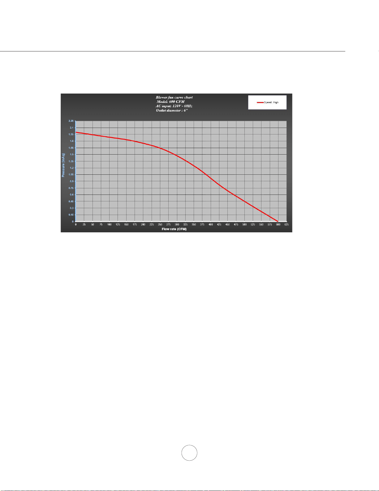
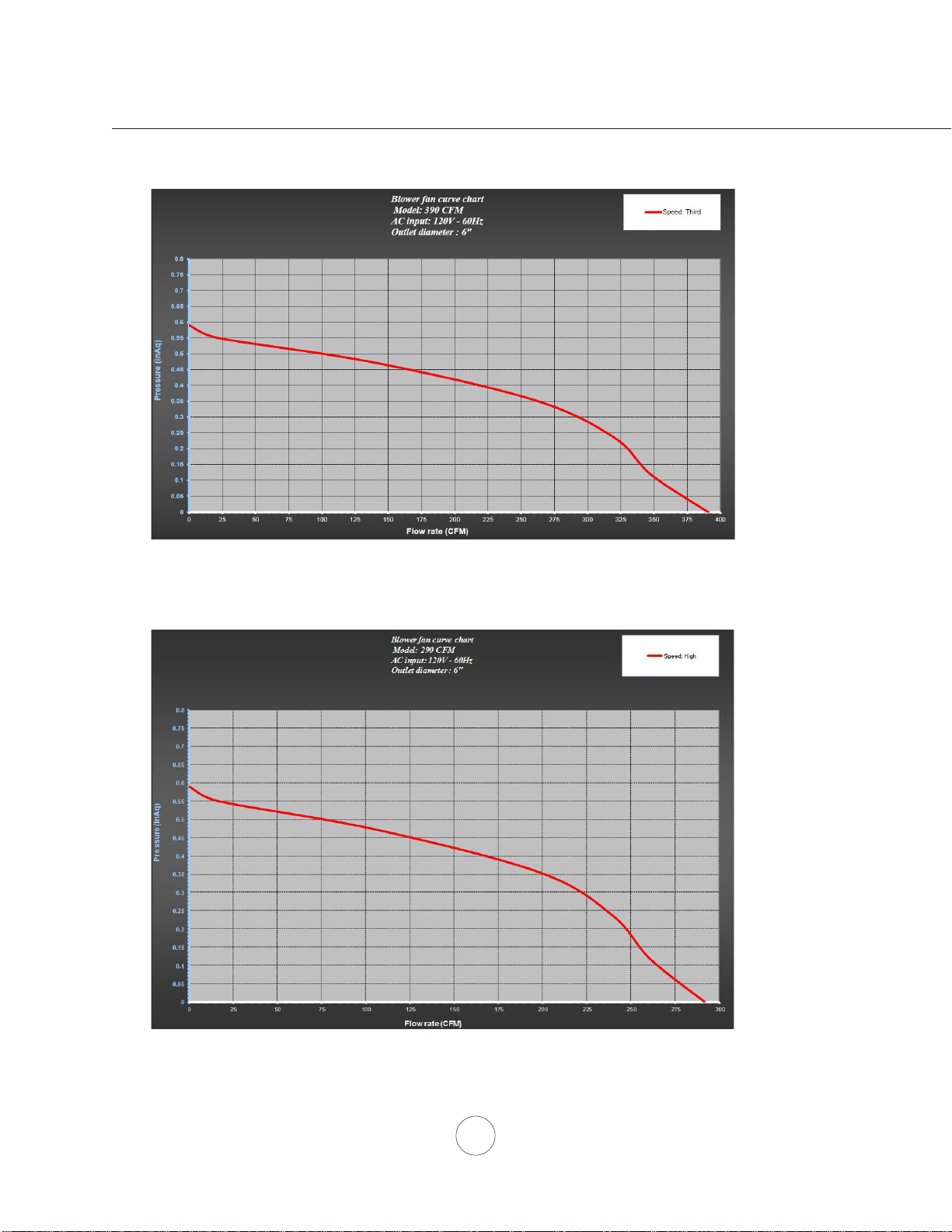
Fan Curve Diagrams
20
www.zephyronline.com
Fan Curve Diagrams
21
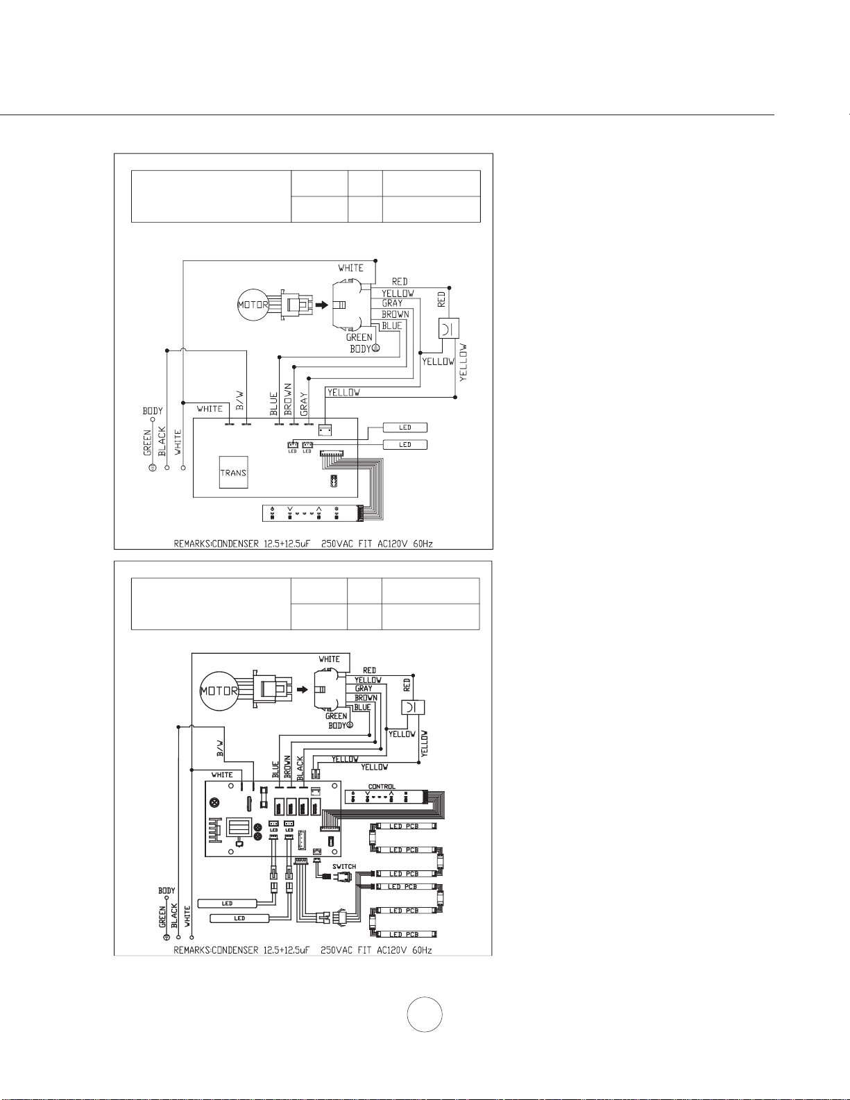
Wiring Diagram
ZAZ, ZRM
CIRCUIT DIAGRAM
VOLTS HZ MAX. AMPS
120 60 4
Power consumption shown
for default 600 CFM blower
FRQ¿JXUDWLRQ
ZLC
CIRCUIT DIAGRAM
VOLTS HZ MAX. AMPS
120 60 4
5A 250V AC
A C 120V
ZLC -E 42 B X - P
ACT 390 CFM - Fan Max. @ 2.3A
ACT 290 CFM - Fan Max. @ 1.9A
ACT 390 CFM - Fan Max. @ 2.3A
ACT 290 CFM - Fan Max. @ 1.9A
Power consumption shown
for default 600 CFM blower
FRQ¿JXUDWLRQ

22
www.zephyronline.com
List of Parts & Accessories
DESCRIPTION PART#
ZAZ Parts & Optional Accessories
$OXPLQXP0HVK)LOWHUHDFK
Recirculating Kit ZRC-02AZ
&KDUFRDO)LOWHU5HSODFHPHQWHDFK =)&
Extension Duct Cover Z1C-00AZ
+\EULG%DIÀH)LOWHU.LW)LOWHUV =)%
ZLC Parts & Optional Accessories
$OXPLQXP0HVK)LOWHUHDFK
Recirculating Kit ZRC-00LC
&KDUFRDO)LOWHU5HSODFHPHQWHDFK =)&
Extension Duct Cover Z1C-00LC
ZRM Parts & Optional Accessories
$OXPLQXP0HVK)LOWHUHDFK
Recirculating Kit, ZRM-E36DS ZRC-02RM
Recirculating Kit, ZRM-E42DS ZRC-01RM
&KDUFRDO)LOWHU5HSODFHPHQWHDFK =)&
Extension Duct Cover Z1C-01RM
To order parts, visit us online at http://store.zephyronline.com or call us at 1.888.880.8368

23
Warranty
1-888-880-8368
STAPLE YOUR RECEIPT HERE
TO OBTAIN SERVICE UNDER WARRANTY OR FOR ANY SERVICE RELATED QUESTIONS, please call:
Zephyr Ventilation, LLC (referred to herein as “we” or “us”) warrants to the original consumer purchaser (referred to
herein as “you” or “your”) of Zephyr products (the “Products”) that such Products will be free from defects in materials
or workmanship as follows:
Three Year Limited Warranty for Parts: For three years from the date of your original purchase of the Products, we
will provide, free of charge, Products or parts (including LED light bulbs, if applicable) to replace those that failed due to
manufacturing defects. We may choose, in our sole discretion, to repair or replace parts before we elect to replace the
Products.
One Year Limited Warranty for Labor: For one year from the date of your original purchase of the Products, we will
provide, free of charge, the labor cost associated with repairing the Products or parts to replace those that failed due to
manufacturing defects. After the first year from the date of your original purchase, you are responsible for all labor costs
associated with this warranty.
Warranty Exclusions: This warranty covers only repair or replacement, at our option, of defective Products or parts and
does not cover any other costs related to the Products including but not limited to: (a) normal maintenance and service
required for the Products and consumable parts such as fluorescent, incandescent or halogen light bulbs, mesh and char-
coal filters and fuses; (b) any Products or parts which have been subject to freight damage, misuse, negligence, accident,
faulty installation or installation contrary to recommended installation instructions, improper maintenance or repair (other
than by us); (c) commercial use of the Products or use otherwise inconsistent with its intended purpose; (d) natural wear
of the finish of the Products or wear caused by improper maintenance, use of corrosive and abrasive cleaning products,
pads, and oven cleaner products; (e) chips, dents or cracks caused by abuse or misuse of the Products; (f) service trips
to your home to teach you how to use the Products; (g) damage to the Products caused by accident, fire, floods, acts of
God; or (h) Custom installations or alterations that impact serviceability of the Products. If you are outside our service
area, additional charges may apply for shipping costs for warranty repair at our designated service locations and for the
travel cost to have a service technician come to your home to repair, remove or reinstall the Products. After the first year
from the date of your original purchase, you are also responsible for all labor costs associated with this warranty.
Limitations of Warranty. OUR OBLIGATION TO REPAIR OR REPLACE, AT OUR OPTION, SHALL BE YOUR SOLE AND
EXCLUSIVE REMEDY UNDER THIS WARRANTY. WE SHALL NOT BE LIABLE FOR INCIDENTAL, CONSEQUENTIAL OR
SPECIAL DAMAGES ARISING OUT OF OR IN CONNECTION WITH THE USE OR PERFORMANCE OF THE PRODUCTS.
THE EXPRESS WARRANTIES IN THE PRECEDING SECTION ARE EXCLUSIVE AND IN LIEU OF ALL OTHER EXPRESS
WARRANTIES. WE HEREBY DISCLAIM AND EXCLUDE ALL OTHER EXPRESS WARRANTIES FOR THE PRODUCTS,
AND DISCLAIM AND EXCLUDE ALL WARRANTIES IMPLIED BY LAW, INCLUDING THOSE OF MERCHANTABILITY AND
FITNESS FOR A PARTICULAR PURPOSE. Some states or provinces do not allow limitations on the duration of an implied
warranty or the exclusion or limitation of incidental or consequential damages, so the above limitations or exclusions may not
apply to you. To the extent that applicable law prohibits the exclusion of implied warranties, the duration of any applicable
implied warranty is limited to the same two-year period described above. Any oral or written description of the Products is for
the sole purpose of identifying the Products and shall not be construed as an express warranty. Prior to using, implementing
or permitting use of the Products, you shall determine the suitability of the Products for the intended use, and you shall assume
all risk and liability whatsoever in connection with such determination. We reserve the right to use functionally equivalent
refurbished or reconditioned parts or Products as warranty replacements or as part of warranty service. This warranty is not
transferable from the original purchaser and applies in the United States and Canada.
To Obtain Service Under Limited Warranty: To qualify for warranty service, you must: (a) notify us at the address or
telephone number stated below within 60 days of the discovery of the defect; (b) give the model number and part identifi-
cation number and serial number; and (c) describe the nature of any defect in the Product or part. At the time of the
request for warranty service, you must present evidence of your proof of purchase and proof of the original purchase
date. If we determine that the warranty exclusions listed abov
e apply or if you fail to provide the necessary documenta-
tion to obtain service, you will be responsible for all shipping, travel, labor and other costs related to the services.
Please check our website for any revisions, www.zephyronline.com.
Zephyr Ventilation Service Department, 2277 Harbor Bay Parkway, Alameda, CA 94502 1-888-880-8368
Limited Warranty
AUG14.0401
Proof of the original purchase
date is needed to obtain
service under warranty

24
www.zephyronline.com
PRODUCT REGISTRATION
Congratulations on your Zephyr range
hood purchase! Please take a moment to
register your new range hood at
www.zephyronline.com/registration
Zephyr Ventilation | 2277 Harbor Bay Pkwy. | Alameda, CA 94502 | 1.888.880.8368
Prompt registration helps in more ways
than one.
IT’S IMPORTANT
Ensures warranty coverage should you
need service.
Ownership verification for insurance
purposes.
Notification of product changes or recalls.
Guide d’utilisation, d’entretien et d’installation
Numéro de modèle : _________________
Numéro de série : _________________
JAN17.0101 © Zephyr Ventilation LLC.
Airflow Control Technology
TM
C
www.zephyronline.com
Anzio Island
ZAZ-M90CS
ZAZ-E42CS
Luce Island
ZLC-M90BS
ZLC-E42BS
Roma Island
ZRM-E36DS
ZRM-E42DS

www.zephyronline.com

1
MISE EN GARDE DE SÉCURITÉ .......................... 2-3
LISTE DU MATÉRIEL ....................................................... 4
INSTALLATION
Feuille de calcul pour le conduit
........................... 5
Espace libre et hauteur de montage
................... 6
Options d’installation pour le conduit
.................. 7
6SpFL¿FDWLRQVGHODKRWWH
......................................... 8-10
Montage de la hotte
................................................... 11-12
Reprise d’air sans conduit
....................................... 13
COMMANDES
ICON Commandes
.................................................... 14-15
ENTRETIEN
1HWWR\DJHGHV¿OWUHVHWGHODKRWWH
...................... 16
DÉPANNAGE
................................................................................ 17
CONVERSION DE LA ACT
...................................................... 18
TABLEAU DE RENDEMENT DU VENTILATEUR
......... 19-20
SCHÉMA DE CÂBLAGE
........................................................... 21
LISTES DES ACCESSOIRES ET DES PIÈCES
............ 22
GARANTIE
..................................................................................... 23
ENREGISTREMENT DU PRODUIT
..................................... 24
Table des matières

Mise en garde de sécurité
LISEZ ET CONSERVEZ CES INSTRUCTIONS
2
www.zephyronline.com
AVERTISSEMENT
POUR RÉDUIRE LES RISQUES D’INCENDIE OU DE DÉCHARGE ÉLECTRIQUE, N’UTILISEZ PAS CET APPAREIL AVEC UN TABLEAU
DE COMMANDE À SEMI-CONDUCTEURS.
AVERTISSEMENT
POUR RÉDUIRE LES RISQUES D’INCENDIE, DE DÉCHARGE ÉLECTRIQUE OU DE BLESSURE, RESPECTEZ CES CONSIGNES :
a. N’utilisez cet appareil que de la manière prévue par le fabricant. Si vous avez des questions, communiquez avec le fabricant.
b. Avant de procéder au nettoyage ou à l’entretien de l’appareil, éteignez l’alimentation du panneau électrique et bloquez le dispositif de
déconnexion pour éviter que l’alimentation électrique ne soit accidentellement rallumée. Si le dispositif de sectionnement d’électricité ne peut
être bloqué, attachez un avertissement (comme une étiquette) bien en vue sur le tableau électrique.
ATTENTION
Pour ventilation générale seulement. N’utilisez pas cet appareil pour évacuer des vapeurs et des matériaux explosifs ou dangereux. Prenez garde
lors de l’utilisation d’agents nettoyants ou de détergents. Ne devrait être utilisé que dans la cuisine de votre maison.
AVERTISSEMENT
POUR RÉDUIRE LES RISQUES DE FEU DE GRAISSE SUR LA SURFACE DE CUISSON :
a. Ne laissez jamais l’appareil sans surveillance lors de son utilisation à haute température. Les débordements par bouillonnement causent de la
fumée et des déversements de graisse qui peuvent prendre feu. Faites chauffer l’huile à des températures basses ou moyennes.
E $OOXPH]WRXMRXUVODKRWWHORUVTXHYRXVFXLVLQH]jKDXWHWHPSpUDWXUHRXTXHYRXVIDLWHVÀDPEHUGHVDOLPHQWV
F 1HWWR\H]IUpTXHPPHQWOHVYHQWLODWHXUVGHODKRWWH/DJUDLVVHQHGHYUDLWMDPDLVV¶DFFXPXOHUGDQVOHVYHQWLODWHXUVRXOHV¿OWUHV
d. Utilisez des poêlons aux dimensions adéquates. Utilisez toujours une batterie de cuisine correspondant aux dimensions de l’élément.
H $VVXUH]YRXVTXHOHYHQWLODWHXUOHV¿OWUHVHWOHVVXUIDFHVRODJUDLVVHSRXUUDLWV¶DFFXPXOHUVRQWWRXMRXUVSURSUHV
f. Utilisez le réglage haut de la hotte seulement lorsque nécessaire.
g. Ne laissez pas la hotte sans surveillance lorsque vous cuisinez.
h. Utilisez toujours une batterie de cuisine et des ustensiles convenant au type et à la quantité de nourriture que vous préparez.
AVERTISSEMENT
POUR RÉDUIRE LES RISQUES DE BLESSURE LORS D’UN INCENDIE SUR LA SURFACE DE CUISSON :
a. ÉTOUFFEZ LES FLAMMES avec un couvercle, une plaque à biscuits ou un plateau de métal et éteignez ensuite le brûleur. PRENEZ GARDE
$8;5,648(6'(%5Ó/85(6LOHVÀDPPHVQHGLVSDUDLVVHQWSDVe9$&8(=/(6/,(8;(7$33(/(=/(6(59,&('¶,1&(1',(
b. NE PRENEZ JAMAIS UN POÊLON EN FEU – Vous pourriez vous brûler.
c. N’UTILISEZ PAS D’EAU, ou un linge à vaisselle mouillé – une violente explosion de vapeur s’ensuivra.
d. Utilisez un extincteur SEULEMENT si :
1. Vous savez que vous possédez un extincteur de classe ABC et vous savez vous en servir.
2. Le feu est faible et ne s’est pas répandu depuis son point d’origine.
3. Vous avez appelé le service d’incendie.
9RXVSRXYH]VRUWLUIDFLOHPHQWGHO¶HQGURLWRYRXVFRPEDWWH]OHIHX
AVERTISSEMENT
POUR RÉDUIRE LES RISQUES D’INCENDIE, DE DÉCHARGE ÉLECTRIQUE OU DE BLESSURE, SUIVEZ LES CONSIGNES SUIVANTES :
D /HVWUDYDX[G¶LQVWDOODWLRQHWGHFkEODJHpOHFWULTXHGRLYHQWrWUHIDLWVSDUXQHSHUVRQQHTXDOL¿pHVHORQOHVVWLSXODWLRQVGHWRXVOHVQRUPHVHW
standards en vigueur, dont les normes des constructions ayant une cote de résistance au feu.
b. Pour prévenir les contre-explosions, une certaine quantité d’air est nécessaire pour la combustion et l’évacuation des gaz par le carneau
(cheminée) de l’appareil de combustion. Respectez les directives du fabricant d’outillage de chauffage et les normes de sécurité comme celles
publiées par la NFPA (Association nationale des services d’incendie), par la Société américaine des ingénieurs en chauffage, réfrigération et
climatisation (ASHRAE) et par les normes des autorités locales.
c. Lorsque vous coupez ou percez un mur ou un plafond, assurez-vous de ne pas endommager le câblage électrique ou toute autre installation
technique dissimulée.
d. Les ventilateurs canalisés doivent toujours évacuer l’air à l’extérieur.
e. N’installez JAMAIS un interrupteur à une distance atteignable depuis un bain ou une douche.
f. Assurez-vous que l’alimentation électrique est éteinte avant de procéder à l’installation, au câblage ou à l’entretien de l’appareil

Mise en garde de sécurité
3
ATTENTION
POUR RÉDUIRE LES RISQUES D’INCENDIE, N’UTILISEZ QUE DES CONDUITS D’AÉRATION EN MÉTAL.
ATTENTION
Pour réduire les risques d’incendie et pour évacuer l’air convenablement, assurez-vous de canaliser l’air à l’extérieur de
la maison. N’installez pas l’échappement du conduit dans les espaces entre les murs, le plafond, le grenier, les vides
sanitaires ou le garage.
Cet appareil n’est pas conçu pour être utilisé au-dessus d’un gril extérieur.
FONCTIONNEMENT
/DLVVH]WRXMRXUVOHVJULOOHVGHVUHWpHWOHV¿OWUHVHQSODFH6DQVFHVpOpPHQWVOHVYHQWLODWHXUVHQPDUFKHSRXUUDLHQW
accrocher des cheveux, des doigts ou des vêtements amples.
Le fabricant se dégage de toute responsabilité dans les cas de non-respect des instructions transmises dans le présent
manuel pour l’installation, l’entretien et l’utilisation adéquate du produit. Le fabricant se dégage également de toute
UHVSRQVDELOLWpSRXUGHVEOHVVXUHVTXLUpVXOWHUDLHQWGHODQpJOLJHQFHORUVGHO¶XWLOLVDWLRQ'HSOXVODJDUDQWLHSUHQG¿Q
automatiquement lors de l’entretien inapproprié de l’appareil.
*NOTE : Veuillez communiquer avec nous ou visitez le www.zephyronline.com pour obtenir des révisions avant de
procéder à des travaux sur commande.
EXIGENCES ÉLECTRIQUES
Important :
Respectez tous les codes et règlements en vigueur.
Il est de la responsabilité du client de :
&RPPXQLTXHUDYHFXQLQVWDOODWHXUpOHFWULFLHQTXDOL¿p
- S’assurer que l’installation électrique est adéquate et qu’elle respecte le Code national de l’électricité, la plus récente
édition* du ANSI/NFPA 70 ou des normes du CSA C22.1-94, le Code canadien de l’électricité, section 1, la plus récente
édition** du code C22.2 No.0-M91 ainsi que tous les codes et réglements en vigueur.
6LOHVFRGHVSHUPHWWHQWO¶XWLOLVDWLRQG¶XQ¿OGHJDUGHLVROpHWTXHYRXVHQXWLOLVH]XQLOHVWUHFRPPDQGpTX¶XQpOHFWULFLHQ
TXDOL¿pGpWHUPLQHVLOHFKHPLQHPHQWGX¿OHVWDGpTXDW
N’effectuez pas la mise à la terre à un tuyau de gaz.
'HPDQGH]jXQpOHFWULFLHQTXDOL¿pVLYRXVQ¶rWHVSDVFHUWDLQTXHODKRWWHDpWpPLVHjODWHUUHDGpTXDWHPHQW
N’introduisez aucun fusible dans le circuit neutre ou de mise à la terre.
*National Fire Protection Association Batterymarch Park, Quincy, Massachusetts 02269
** CSA International 8501 East Pleasant Valley Road, Cleveland, Ohio 44131-5575
Cet appareil requiert une alimentation électrique de 120V 60Hz. Il doit être connecté à un circuit terminal individuel
dûment mis à la terre, protégé par un disjoncteur de circuit ou un fusible temporisé de 15 ou 20 ampères. Le câblage doit
FRPSWHU¿OVDYHFPLVHjODWHUUH9HXLOOH]YRXVUpIpUHUDX'LDJUDPPHpOHFWULTXHpWLTXHWpVXUO¶DSSDUHLO
Un raccord de câble (non inclus) pourrait également être exigé par les normes et réglementations locales. Informez-vous
des exigences et des normes locales. Achetez et installez le connecteur approprié si nécessaire.
Liste du matériel
4
www.zephyronline.com
PIÈCES FOURNIES
A
B
Front of Hood
C
L
/
Cut-Out Shaded Area
(20) M4 x 8
(ZLC x 8)
(2) Consoles de support
(ZLC seulement)
(3) Capuchons
de connexion
(4) rondelles
ø12 OD / ø5
(4) vis à bois
M4 x 1”
(4) 3/16 x 1/4
Vis de mécanique
(1) Trousse de quincaillerie
(1) Registre circulaire de 6” (préinstallé)
CONTENU DE LA TROUSSE DE QUINCAILLERIE
(2) Pièces de recouvrement
supérieures pour le conduit
(1) Cadre de fixation supérieur
(2) Pièces de recouvrement
inférieures pour le conduit
(1) Cadre de fixation inférieur
(1) Boîtier de
la hotte
(2) Brite Strip™ LED
(2) Filtres à deflecteur
(ZAZ-E42 & ZRM-E42 x 3)
(1) vis de sûreté
M4 x 12
(1) Gabarit de plafond en papier
PIÈCES NON FOURNIES
- Conduit et tous les outils d’installation
- Raccord de câble (si exigé par les codes en vigueur)
- Accessoire – prolongement pour recouvrement de conduit
- Accessoire – ensemble de reprise d’air
(1) Support de cadre de fixation
(ZAZ ONLY)
5
Tot a l
=
3- 1/4” x 10”
1 pi x ( ) =
pi
5 pi x ( ) =
pi
20 pi x ( ) =
pi
6”, 7”, 8”, 10”
15 pi
x ( ) =
pi
6”, 7”, 8”, 10”
9 pi x ( ) =
pi
pi
6”, 7”, 8”, 10”
1 pi x ( ) =
pi
Tot a l
=
6”, 7”, 8”, 10”
30 pi x ( ) =
pi
pi
pi
pi
6”, 7”, 8”, 10”
30 pi x ( ) =
pi
1 pi x ( ) =
pi
16 pi x ( ) =
pi
8 pi x ( ) =
pi
23 pi x ( ) =
pi
7” to 6” or
8” to 7” circ.
reducteur
conique
25 pi x ( ) =
pi
3- 1/4” x 10”
15 pi x ( ) =
pi
3- 1/4” x 10”
9 pi x ( ) =
pi
3- 1/4” x 10”
24 pi x ( ) =
pi
30 pi x ( ) =
pi
pi x ( ) =
pi
15
6”, 7“, 8”
circ.
bouchone de
l’air
Pièces de conduit
Longueur x
Nombre utilisé
rect., droit
circ., droit
rect.,
coude à 90º
rect.,
coude à 45º
rect.,
coude plat
à 90º
circ.,
coude à 90º
coude à 45º
Sous-total - colonne 1=
Longueur maximale du conduit d’aération :
Pour un mouvement d’air convenable, la longueur totale d’un conduit
d’aération ne devrait pas compter plus que l’équivalent de 100 pieds.
Pièces de conduit
Longueur x
Nombre utilisé
6” circ. à
rect. de
3-1/4" x 10",
coude à 90º
6” circ. à
rect. de
3-1/4" x 10"
6” circ. à
rect. de
3-1/4" x 10"
6” circ. à
rect. de
3-1/4" x 10",
coude à 90º
7” circ. à
rect. de
3-1/4" x 10"
7” circ. à
rect. de
3-1/4" x 10",
coude à 90º
3-1/4” x 10”
embout mural
rect./registre
embout
mural
circ./registre
chapeau de
toiture circ.
Sous-total - colonne 2 =
Sous-total - colonne 1 =
Total du conduit =
Installation – Feuille de calcul pour le conduit d’aération
Installation – Espace libre et hauteur de montage
6
www.zephyronline.com
CONDUIT D’AÉRATION
Un conduit circulaire de 6” doit être utilisé pour assurer une circulation
d’air maximale.
N’utilisez que des conduits en métal rigide. Les conduits souples pourraient
réduire la circulation d’air jusqu’à 50 %.
Utilisez la feuille de calcul pour obtenir la longueur totale du conduit (page
5).
Lorsqu’il est possible de le faire, diminuez TOUJOURS le nombre de
pièces et de changements de direction. Si un long tronçon de conduit est
nécessaire, augmentez le diamètre du conduit de 6” à 8”.
Si des changements de direction ou des adaptateurs sont nécessaires,
installez-les le plus loin possible de l’ouverture et le plus éloigné possible
l’un de l’autre.
La hauteur de montage minimale ne devrait pas être moins de 26”.
La hauteur de montage maximale ne devrait pas outrepasser 34”.
Il est important d’installer la hotte à la hauteur de montage adéquate. Les
hottes installées trop basses pourraient être endommagées par la chaleur
en plus de présenter des risques d’incendie plus élevés tandis que les
KRWWHVLQVWDOOpHVWURSKDXWHVVHURQWGLI¿FLOHVjDWWHLQGUHHWYHUURQWOHXU
HI¿FDFLWpHWOHXUUHQGHPHQWUpGXLWV
Si elles sont disponibles, consultez les exigences de hauteur d’espace libre
requise par le fabricant de la cuisinière ainsi que la hauteur recommandée
de montage de la hotte au-dessus de la surface de cuisson. Informez-vous
toujours des normes et des réglementations locales en vigueur pour toute
différence par rapport aux normes du fabricant.
Ensemble de recouvrement de conduit disponible pour les plafonds
atteignant 12 pieds. Numéro de pièce et information pour commander
disponibles à la page 22.
ENDOMMAGEMENT LORS DE LA LIVRAISON/INSTALLATION :
9HXLOOH]YRXVDVVXUHUTXHWRXWHVOHVSLqFHVGHO¶DSSDUHLOQHVRQWSDV
endommagées avant l’installation.
6LO¶DSSDUHLOHVWHQGRPPDJpGXUDQWODOLYUDLVRQUHWRXUQH]O¶DSSDUHLOj
O¶HQGURLWRYRXVO¶DYH]DFKHWpSRXUUpSDUDWLRQRXUHPSODFHPHQW
6LO¶DSSDUHLOHVWHQGRPPDJpSDUOHFOLHQWODUpSDUDWLRQRXOH
remplacement est à la charge du client.
6LO¶DSSDUHLOHVWHQGRPPDJpSDUO¶LQVWDOODWHXUVLDXWUHTXHOHFOLHQWOH
client et l’installateur doivent en venir à une entente pour la réparation ou
le remplacement.
A
B
C
D
E
F
ZAZ ZLC ZRM
Recouvrement de conduit standard
Prolongement de recouvrement de conduit
A
B
C
D
E
F
ZAZ ZLC ZRM
28”
31”
39”
90” (7’ 6”)
80”
150” (12’ 6”)
28”
90” (7’ 6”)
47”
51”
80”
150” (12’ 6”)
109” (9’ 1”)
113” (9’ 5”)
36”
50”
98” (8’ 2”)
120” (10’)
47”
51”
80”
109” (9’ 1”)
113” (9’ 5”)
150” (12’ 6”)
A : Hauteur de la hotte minimum avec conduit
B : Hauteur de la hotte minimum avec reprise d’air
C : Hauteur de la hotte maximum
D : Hauteur de plafond minimum avec conduit
E : Hauteur de plafond minimum avec reprise d’air
F : Hauteur de plafond maximum
min. A
min. B
max. C
36”
26” min.
34” max.
min. D
min. E
max. F
31-
1/2
”
93-
1/2
” (7’ 9-
1/2
”)
32-
1/2
”
46-
1/2
”
94-
1/2
” (7’ 10-
1/2
”)
116-
1/2
” (9’ 8-
1/2
”)
93” (7’ 9”)
109” (9’ 1”)
50-
1/2
”
50-
1/2
”
112-
1/2
” (9’ 4-
1/2
”)
112-
1/2
” (9’ 4-
1/2
”)
7
AVERTISSEMENT DE RISQUE D’INCENDIE
N’évacuez ou ne terminez JAMAIS l’échappement du conduit dans les espaces entre les murs, les vides
sanitaires, le plafond, le grenier, ou le garage. Tous les échappements doivent être dirigés à l’extérieur de la
maison, à moins que l’option de reprise d’air ne soit utilisée.
N’utilisez que des conduits en métal pour cloison simple.
Fixez toutes les pièces du conduit avec des vis à tôle et isolez tous les joints avec du ruban adhésif en toile ou
GXUXEDQUpÀHFWHXUFHUWL¿p
Quelques options pour le conduit d’aération
Installation – Options pour le conduit d’aération
Pente de la toiture
avec solin et chapeau
Bouche d’aération
de mur latéral avec
clapet antirefoulement
Retombée de plafond ou vide sanitaire
Reprise
d’air sans conduit
8
www.zephyronline.com
Installation – 6SpFL¿FDWLRQVGHODKRWWH=$=
C/L
8 1/8”
7 9/16”
3 9/16”
13/16”
4 3/16”
8 1/4”
STANDARD
min. ducted - 31 1/2”
min. recirc. - 36”
max. - 50”
Z1C-00AZ
min. ducted - 47”
min. recirc. - 51”
max. - 80”
10 5/8”
25 9/16”
1 3/16”
11”
35 7/16”, 41 15/16”
9 7/16”
16 9/16”
5 1/4”
5 15/16”
3 1/2”
AC In
1 1/4”
C/L
C/L
1 7/8”
5 5/16”
DEVANT CÔTÉ
DESSUS de la HOTTE CADRE DE FIXATION SUPÉRIEUR
(vue du dessus)
9
FRONT
11”
35 7/16”, 41 7/8”
9 7/16”
12
3/8”
25 9/16”
10 5/8”
STANDARD
min. ducted - 28”
min. recirc. - 32
1/2”
max. - 46
1/2”
Z1C-00LC
min. ducted - 47”
min. recirc. - 51”
max. - 80”
6”
2 1/2”
1 1/4”
3 7/16”
C/L
C/L
7 9/16”
6
3/4”
8 1/8”
7
13/16”
DEVANT CÔTÉ
DESSUS de la HOTTE CADRE DE FIXATION SUPÉRIEUR
(vue du dessus)
Installation – 6SpFL¿FDWLRQVGHODKRWWH=/&
10
Installation – 6SpFL¿FDWLRQVGHODKRWWH=50
35 7/8”, 41 7/8”
14”
3”
26 7/8”
STANDARD
min. ducted - 28”
min. recirc. - 31”
max. - 39”
Z1C-01RM EXTENSION
min. ducted - 50 1/2”
min. recirc. - 50 1/2”
max. - 80”
12”
11 3/16”
9 11/16”
AC-IN
2
CL
3/8"
4 3/16"12
7/16
"
ø 6"
11"
9 7/16"
DEVANT CÔTÉ
DESSUS de la HOTTE
11
1. Déterminez l’emplacement pour l’installation de la hotte et collez temporairement le gabarit en papier (inclus avec
la hotte) au plafond. Dans le plafond, faites un trou correspondant à la zone interne ombragée du gabarit. C’est là
que passeront le conduit et les câbles électriques. Au besoin, ajoutez les blocs de bois (min. 2” x 4”) aux solives de
plafond, derrière la cloison sèche, pour renforcer le plafond (FIG. A#1) *. Fixez deux vis à bois 1-1/2” aux points A et
B du gabarit en papier (FIG. G). Ne serrez pas les vis jusqu’au bout et laissez dépasser environ 1/4”.
'pWHUPLQH]ODKDXWHXUG¶LQVWDOODWLRQGHODKRWWHHWDMXVWH]OHVFDGUHVGH¿[DWLRQLQIpULHXUHWVXSpULHXUHQFRQVpTXHQFH
$VVHPEOH]OHVFDGUHVGH¿[DWLRQjO¶DLGHGHKXLWYLV0[SDUEUDVGHFDGUHGH¿[DWLRQ),*$
6RXOHYH]O¶DVVHPEODJHGHVFDGUHVGH¿[DWLRQYHUVOHSODIRQGHQYRXVDVVXUDQWTXHOHPRW©)URQWªVLWXpVXUOHGHVVXV
GHVFDGUHVGH¿[DWLRQHVWVXUODPrPHIDFHGHODKRWWHROHVFRPPDQGHVVRQWVLWXpHV),*%/HVHQFRFKHVHQ
WURXGHVHUUXUHVLWXpHVVXUOHGHVVXVGXFDGUHGH¿[DWLRQGHYUDLHQWFRwQFLGHUDYHFOHVYLVjERLVSUpDODEOHPHQW¿[pHV
DXSODIRQG)DLWHVJOLVVHUOHFDGUHGH¿[DWLRQYHUVODSDUWLHpWURLWHGHVHQFRFKHVHQWURXGHVHUUXUHSRXUOH¿[HUHQ
SODFH,QVWDOOH]OHVGHX[GHUQLqUHVYLVjERLV0[´DYHFGHVURQGHOOHVGDQVOHVGHX[FRLQVGXFDGUHGH¿[DWLRQ
VXSpULHXUTX¶LOUHVWHSRXU¿[HUOHFDGUHDXSODIRQG6HUUH]WRXWHVOHVYLV
4. Soulevez la hotte et alignez les quatre vis de montage préinstallées de la partie supérieure du boîtier de la hotte (FIG.
$DYHFOHVTXDWUHHQFRFKHVHQWURXGHVHUUXUHGXFDGUHGH¿[DWLRQLQIpULHXU),*&)DLWHVJOLVVHUODKRWWHYHUVOD
SDUWLHpWURLWHGHVHQFRFKHVHQWURXGHVHUUXUHSRXUOH¿[HUHQSODFH6HUUH]OHVTXDWUHYLVjODPDLQSRXUELHQ¿[HUOD
KRWWHDXFDGUHGH¿[DWLRQLQIpULHXU$MRXWH]HQVXLWHXQHYLVGHVUHWp0[),*)S
/DKRWWHHVWFRQoXHSRXUrWUHLQVWDOOpHjXQSODIRQG¿QL
!
ATTENTION : Compte tenu du poids
et des dimensions de la hotte, au moins
deux installateurs sont nécessaires.
Installation – 0RQWDJHGHODKRWWH
1
2
Solives de plafond
Bloc de bois
Cadre de fixation
supérieur
Bras du cadre de fixation
Cadre de fixation
inférieur
Boîtier de
la hotte
3
Vis de montage
(préinstallées)
4
Cadre de fixation inférieur
(est fixé à la partie supérieure du boîtier du ventilateur)
Encoches en trou
Devant – commandes à l’avant
Dos
FIG. A
FIG. C
FIG. B
Side
Front
XP022220
A
B
Zone de découpage ombragée
FIG. G
Devant

12
www.zephyronline.com
Installation – 0RQWDJHGHODKRWWH
5. Enlevez le ruban qui retient le support de montage du dispositif électronique à la hotte et placez-le comme sur la FIG. E.
Installez l’électricité et le conduit. Les normes locales peuvent exiger l’’utilisation d’un raccord de câble, non fourni (FIG.
E). Scellez les conduits d’aération avec du ruban à conduit en aluminium.
0HWWH]ODKRWWHVRXVWHQVLRQSRXUYRXVDVVXUHUGXERQIRQFWLRQQHPHQWGHWRXWHVOHVIRQFWLRQVHWYpUL¿H]V¶LO\DGHVIXLWHV
d’air autour du ruban à conduit.
$VVHPEOH]OHVSLqFHVGHUHFRXYUHPHQWGHFRQGXLWDYHFOHVWURXVGHVJULOOHVG¶DpUDWLRQHW¿[H]OHVHQVHPEOHDXFDGUH
du support supérieur à l’aide des bandes magnétiques. Note : Si vous utilisez la hotte en mode de reprise d’air, vous
GHYH]¿[HU ODSLqFHDYHFOHVWURXV SRXUGpÀHFWHXUV DXFDGUH GH¿[DWLRQVXSpULHXUDYDQWG¶DVVHPEOHU OHVSLqFHV GH
recouvrement de conduit. Consultez la page 11 pour plus de détails.
)L[H]OHVSLqFHVGHUHFRXYUHPHQWVVXSpULHXUHVDXFDGUHGH¿[DWLRQVXSpULHXUHjO¶DLGHGHTXDWUHYLV[´),*'
$VVHPEOH] OHV SLqFHV GH UHFRXYUHPHQW LQIpULHXUHV SDUGHVVXV OHV SLqFHV GH UHFRXYUHPHQW VXSpULHXUHV HW ¿[H]OHV
ensemble à l’aide des bandes magnétiques.
AVERTISSEMENT : Le câblage électrique doit être effectué par une ou
!
des personnes qualifiées selon les stipulations de tous les normes et
standards en vigueur. Éteignez l’alimentation électrique à l’entrée de
service avant de procéder au câblage.
1
Cadre de fixation
supérieur
Pièces de recouvrement
supérieures
Pièces de recouvrement
inférieures
Cadre de fixation
inférieur
FIG. D
Raccord de câble
Raccord de câble
Un raccord de câble (non inclus)
pourrait également être exigé par les
normes et réglementations locales.
Informez-vous des exigences et des
normes locales. Achetez et installez le
connecteur approprié si nécessaire.
FIG. E
FIG. F

13
Installation – Reprise d’air sans conduit
/DFRQ¿JXUDWLRQGH UHSULVHVDQVFRQGXLWDpWpFRQoXHSRXU OHVDSSOLFDWLRQVRLOHVWLPSRVVLEOHG¶LQVWDOOHUXQFRQGXLW
d’aération. Lorsque transformée, la hotte fonctionne comme une hotte de reprise d’air plutôt que comme un système
G¶pYDFXDWLRQG¶DLU /HVYDSHXUV HW IXPpHVGH FXLVVRQVRQWDVSLUpHV HW¿OWUpHVSDU XQHQVHPEOHRSWLRQQHO GH¿OWUHV j
FKDUERQ/¶DLUHVWHQVXLWHSXUL¿pHWUHGLULJpjO¶LQWpULHXUGHODPDLVRQ
Nous recommandons de TOUJOURS évacuer l’air à l’extérieur de la maison en utilisant le conduit en place ou, s’il y a
SRVVLELOLWpHQLQVWDOODQWXQQRXYHDXFRQGXLW/DKRWWHHVWSOXVHI¿FDFHORUVTX¶XWLOLVpHFRPPHV\VWqPHG¶pYDFXDWLRQG¶DLU
9RXVQHGHYULH]UHFRXULUjODFRQ¿JXUDWLRQGHUHSULVHG¶DLUTXHORUVTX¶LOHVWLPSRVVLEOHG¶LQVWDOOHUXQFRQGXLWG¶DpUDWLRQ
/RUVTXHODFRQ¿JXUDWLRQGHUHSULVHG¶DLUHVWFKRLVLHXQHQVHPEOHGH¿OWUHVjFKDUERQGRLWrWUHLQVWDOOpVXUO¶HQVHPEOH
GH¿OWUHVjWDPLVHQDOXPLQLXP&RPPDQGH]OHVHQYRXVUpIpUDQWDXQXPpURGHSLqFHFLGHVVRXV/HV¿OWUHVjWDPLVHQ
DOXPLQLXPVRQWFRQoXVSRXUFDSWXUHUOHVUpVLGXVGHFXLVVRQHWOHV¿OWUHVjFKDUERQRSWLRQQHOVDLGHQWjODSXUL¿FDWLRQGHV
vapeurs et fumées de la cuisson lors de la reprise d’air.
ENSEMBLE DE REPRISE D’AIR (REQUIS SI AUCUN CONDUIT N’EST UTILISÉ
/¶HQVHPEOHFRPSUHQGGHV¿OWUHVjFKDUERQGHVVXSSRUWVHWXQGpÀHFWHXUG¶DLU
0RGqOHGHKRWWH1XPpURGHSLqFH)LOWUHVHWVXSSRUWVSDUSDTXHW
ZAZ ZRC-02AZ 2
ZLC ZRC-00LC 1
ZRM-E36DS ZRC-02RM 2
ZRM-E42DS ZRC-01RM 3
1. Procurez-vous l’ensemble de reprise d’air en utilisant le numéro de pièce ci-dessus
)L[H]ODSODTXHGXGpÀHFWHXUG¶DLUDXFDGUHGH¿[DWLRQVXSpULHXU/HVF{WpVRXYHUWVGHODSODTXHGXGpÀHFWHXUG¶DLU
GHYUDLHQWVHWURXYHUVXUOHVF{WpVSRXUGLULJHUO¶DLUGDQVOHVWURXVGHVGpÀHFWHXUVVLWXpVVXUODSLqFHGHUHFRXYUHPHQW
VXSpULHXU,QVWDOOH]OHFRQGXLWGH´jODSDUWLHVXSpULHXUHGHODKRWWHHW¿[H]OHjODSODTXHGXGpÀHFWHXUG¶DLU
5HWLUH]OHV¿OWUHVjWDPLVHQDOXPLQLXPGHODKRWWH,QVWDOOH]OHVVXSSRUWVGHV¿OWUHVjFKDUERQGDQVO¶RXYHUWXUHGX¿OWUH
5pLQVWDOOH]OHV¿OWUHVjWDPLVHQDOXPLQLXP
$OOXPH]O¶LQGLFDWHXUGHFKDQJHPHQWGX¿OWUHjFKDUERQVXUOHSDQQHDXLQGLFDWHXUFRQVXOWH]ODSDJHSRXUSOXVGH
GpWDLOV/HPLFURSURFHVVHXUGHVFRPPDQGHVYRXVLQGLTXHUDOHPRPHQWRFKDQJHUOH¿OWUHjFKDUERQDSUqV
KHXUHVG¶XWLOLVDWLRQFRQWLQXH&RPPDQGH]GHV¿OWUHVjFKDUERQGHUHPSODFHPHQWHQFRQVXOWDQWODOLVWHFLGHVVRXV
/HV¿OWUHVjFKDUERQGRLYHQWrWUHUHPSODFpVDSUqVKHXUHVG¶XWLOLVDWLRQRXDSSUR[LPDWLYHPHQWWRXVOHVPRLVj
raison de 1-2 heures d’utilisation quotidienne).
NOTE : Pour plus de détails, consultez le manuel de l’ensemble de reprise d’air.
)LOWUHVjFKDUERQGHUHPSODFHPHQW
0RGqOHGHKRWWH1XPpURGHSLqFH4XDQWLWpjFRPPDQGHU
ZAZ Z0F-C091 2
ZLC Z0F-C092 1
ZRM-E36DS Z0F-C002 2
ZRM-E42DS Z0F-C002 3
NE NETTOYEZ PAS LES FILTRES À CHARBON. Vous pourriez avoir à
FKDQJHUOHV¿OWUHVjFKDUERQSOXVVRXYHQWVHORQYRVKDELWXGHVFXOLQDLUHV
14
www.zephyronline.com
Lumières :
Allumer/Veilleuse/Éteindre
Afficheur (vitesse, arrêt à retardement, nettoyage/changement des filtres)
Choix de 5 vitesses
Mise en marche/Arrêt
à retardement
1 MISE EN MARCHE/ARRÊT À RETARDEMENT
Fonction de la touche de mise en marche
- La touche permet d’allumer et d’éteindre toutes les fonctions de la hotte (ventilateurs et lumières).
- La hotte se rappelle la dernière vitesse et le dernier niveau d’éclairage utilisés.
(Exemple : Appuyez sur la touche lorsque le ventilateur fonctionne à la vitesse 4 et que les
lumières sont allumées à haute intensité. Si vous appuyez de nouveau sur la touche , le ventila-
teur repart à la vitesse 4 et les lumières se rallument à haute intensité.)
Fonction de la touche d’arrêt à retardement
- Lorsque le ventilateur est en cours d’utilisation, appuyez sur la touche et maintenez-la enfoncée
pendant deux secondes. Le ventilateur passe à la vitesse 1 et le compte à rebours de la minuterie de
l’arrêt à retardement commence.
Les DEL et s’illuminent et clignotent lentement en fonction du temps qu’il
reste avant l’arrêt automatique du ventilateur et des lumières.
- Appuyez sur la touche lorsque la fonction d’arrêt à retardement est en cours d’utilisation pour
éteindre la hotte et annuler la fonction d’arrêt à retardement.
Vérification de la ACT
- La technologie de contrôle du débit d’air permet à l’installeur d’ajuster la quantité maximale
d’évacuation de pi /min du ventilateur afin de respecter les codes et règlements en vigueur.
- Pour vérifier la quantité maximale d’évacuation de pi /min du ventilateur :
- Lorsque la hotte est éteinte, appuyez sur la touche et maintenez-la enfoncée pendant
deux secondes. Si cinq icônes de ventilateur s’illuminent, le réglage est ajusté au maximum.
Si quatre icônes s’illuminent, le maximum est de 390 pi /min. Si trois icônes s’illuminent, le
maximum est de 290 pi /min.
2 TOUCHE DE CHOIX DE VITESSE
Touche de réduction de vitesse du ventilateur
- Appuyez sur cette touche pour réduire la vitesse du ventilateur. 5, 4, 3, 2, 1.
- Si le ventilateur est à la vitesse 1 et que vous appuyez sur cette touche, le ventilateur s’éteint.
Touche d’augmentation de vitesse du ventilateur
- Appuyez sur cette touche pour augmenter la vitesse du ventilateur. 1, 2, 3, 4, 5.
- Si le ventilateur est éteint et que vous appuyez sur cette touche, le ventilateur s’allume à la vitesse 1.
Choix de vitesse avec ACT activée
- Lorsque la ACT est activée, le nombre de vitesses du ventilateur est réduit comme suit :
- 390 pi /min = 4 vitesses maximum
- 290 pi /min = 3 vitesses maximum
Touche d’illumination
du verre
5
ZLC seulement
3
3
3
3
3
3
Commandes - ICON Commandes
15
3 TOUCHE DE CONTRÔLE DES LUMIÈRES
- Il existe deux intensités : haute et basse.
- Lorsque les lumières sont éteintes, appuyez une fois pour les allumer à haute intensité. Appuyez de
nouveau pour les mettre en veilleuse. Appuyez encore une fois pour les éteindre.
4 AFFICHEUR
Rappel de nettoyage des filtres à tamis (toujours activé)
- Après 30 heures d’utilisation du ventilateur, l’icône commence à clignoter lentement, indiquant
qu’il est temps de nettoyer les filtres à tamis.
- Pour réinitialiser : Lorsque la hotte est éteinte : tenez la touche enfoncée pendant trois
secondes. Tous les indicateurs DEL clignotent deux fois, confirmant la réinitialisation de la minuterie
de 30 heures.
Indicateur de remplacement des filtres à charbons (désactivé par défaut, doit être activé lors de
l’utilisation du mode de recirculation d’air)
- Pour activer le rappel de remplacement des filtres à charbon :
- Lorsque la hotte est éteinte, tenez les touches et enfoncées simultanément pendant
deux secondes. Tous les indicateurs DEL s’illuminent pendant trois secondes, confirmant
l’activation du rappel de remplacement des filtres à charbon.
- Pour désactiver le rappel de remplacement des filtres à charbon :
- Lorsque la hotte est éteinte, tenez les touches et enfoncées simultanément pendant
deux secondes. Tous les indicateurs DEL clignotent deux fois, confirmant la désactivation du
rappel de remplacement des filtres à charbon.
- Après 120 heures d’utilisation du ventilateur, la touche clignote lentement, indiquant que les filtres
à charbon doivent être remplacés.
- Pour réinitialiser : Lorsque la hotte est éteinte : tenez la touche enfoncée pendant deux
secondes. Tous les indicateurs DEL clignotent deux fois, confirmant la réinitialisation de la minuterie
de 120 heures.
5 TOUCHE D’ILLUMINATION DU VERRE (ZLC Seulement)
- Appuyez sur cette touche pour illuminer le verre en blanc, bleu, jaune et pour l’éteindre.
- Appuyez sur cette touche pendant trois secondes pour activer le mode démo. Lorsque ce mode est
activé, les couleurs changent graduellement toutes les dix secondes.
- Lorsque vous appuyez sur pour allumer les ampoules DEL, l’illumination du verre s’éteint
automatiquement.
Commandes - ICON Commandes
16
ENTRETIEN DES SURFACES:
Nettoyez régulièrement les surfaces de la hotte avec de l’eau savonneuse chaude et un chiffon de coton propre.
N’utilisez pas de détergent abrasif ou corrosif, de laines d’acier ou de tampons à récurer; ils égratigneront et
endommageront les surfaces.
Pour les taches plus tenaces, utilisez du produit dégraissant liquide.
Après le nettoyage, vous pouvez polir les surfaces avec des produits de polissage à acier inoxydable non
abrasifs pour redonner de l’éclat et du lustre aux surfaces. Frottez toujours doucement, avec un chiffon de coton
propre, et dans le sens du grain.
1¶XWLOLVH]SDVGHSURGXLWVjEODQFKLUDXFKORUHRXG¶DJHQWVQHWWR\DQWV©RUDQJHª
)LOWUHjGHÀHFWXHU
/HV¿OWUHVjWDPLVHQDOXPLQLXPLQVWDOOpVSDUOHIDEULFDQWRQWSRXUIRQFWLRQGH¿OWUHUOHVUpVLGXVHWODJUDLVVH
de cuisson. Ils ne nécessitent aucun remplacement sur une base régulière, mais doivent être gardés propres.
Enlevez-les et nettoyez-les à la main ou au lave-vaisselle avec de l’eau tiède. Vaporisez avec du détergent pour
graisse et laissez tremper pour éliminer la saleté accumulée.
6pFKH]OHV¿OWUHVHWUpLQVWDOOH]OHVDYDQWG¶XWLOLVHUODKRWWH
3RXUHQOHYHUOHV¿OWUHVjGHÀHFWXHU
1. Poussez sur les poignées à ressort
7LUH]VXU OD SRLJQpH GX ¿OWUHYHUVOH EDV SRXU
HQOHYHUOH¿OWUH
Entretien - 1HWWR\DJHGHODKRWWHHWGHV¿OWUHV
17
Dépannage
PROCÉDURES DE DÉPANNAGE
Problème Cause Solution
Après l’installation,
l’appareil ne
fonctionne pas.
1. Le bloc d’alimentation n’est pas allumé 1. Assurez-vous que l’alimentation du disjoncteur et de
l’appareil est allumée
2. La ligne électrique et le raccord de câble ne sont pas
correctement branchés
9pUL¿H]TXHOHEUDQFKHPHQWGHO¶DSSDUHLODpWpIDLW
correctement
/HV¿OVpOHFWULTXHVGXWDEOHDXGHFRQWU{OHHWGH
commande sont débranchés
$VVXUH]YRXVTXHOHV¿OVpOHFWULTXHVHQWUHOHV
tableaux de contrôle et de commande sont branchés
convenablement
4. Tableau de contrôle/commande défectueux 4. Remplacez le tableau de contrôle/commande
Les lumières
fonctionnent, mais
le ventilateur ne
tourne pas.
1. Le ventilateur est défectueux, possiblement bloqué 1. Remplacez le ventilateur
2. Le système de protection thermale détecte que le
moteur est trop chaud pour fonctionner et l’éteint.
2. Le moteur fonctionnera normalement lorsque le
système de protection thermale aura refroidi
3. Le condensateur est endommagé 3. Remplacez le condensateur.
4. Tableau de contrôle/commande défectueux 4. Remplacez la pièce défectueuse
L’appareil vibre. /HPRWHXUQ¶HVWSDVELHQ¿[pHQSODFH 1. Fixez solidement le moteur en place
2. La roue du ventilateur est endommagée 2. Remplacez le ventilateur
/DKRWWHQ¶HVWSDVELHQ¿[pHHQSODFH 9pUL¿H]O¶LQVWDOODWLRQGHODKRWWH
Le moteur
fonctionne, mais
pas les lumières.
1. L’ampoule DEL est défectueuse 1. Remplacez l’ampoule DEL
2. Le câble de l’ampoule DEL est débranché du tableau
de commande.
9pUL¿H]ODFRQQH[LRQGHVFkEOHVGHO¶DPSRXOH'(/
du tableau de commande.
3. Le connecteur de l’ampoule DEL est débranché. 9pUL¿H]ODFRQQH[LRQGHO¶DPSRXOH'(/
Le ventilateur
s’allume seul
1. Une lumière ou lampe de la cuisine éclaire directement
le tableau de commande.
1. Le tableau de commande est sensible à la lumière
Une source de lumière directe sur le tableau
de commande peut perturber les fonctions des
interrupteurs.
Les différentes
vitesses du
ventilateur
semblent toutes les
mêmes.
1. Vous n’utilisez pas le bon diamètre de conduit. 1. Installez un conduit circulaire d’au moins 6” et
changez le type de conduit pour en utiliser un qui est
rigide, et non souple.
La hotte ne
fonctionne pas
bien.
1. La hotte est possiblement installée trop haut par rapport
à la cuisinière
1. Ajustez la distance entre la surface de la cuisinière et
la base de la hotte entre 26” et 34”
2. Du vent provenant d’une fenêtre ou d’une porte ouverte
avoisinante nuit à la ventilation
2. Fermez toutes les portes et fenêtres pour éliminer
les courants d’air
3. L’ouverture du conduit ou le conduit lui-même est
bloqué
3. Fermez toutes les portes et fenêtres pour éliminer
les courants d’air
4. L’ouverture du conduit est contre le vent 4. Ajustez l’orientation de l’ouverture du conduit
5. Mauvaises dimensions de conduit d’aération 5. Remplacez le conduit par un conduit adéquat de 8”
ou plus.
/H¿OWUHHQPpWDO
vibre.
/H¿OWUHHQPpWDOHVWGHVVHUUp 1. Assurez-vous que les attaches métalliques de la
SRLJQpHQHVRQWSDVEORTXpHV2XUHPSODFH]OH¿OWUH
à tamis.
18
www.zephyronline.com
Conversion De La ACT
7HFKQRORJLHGHFRQWU{OHGXGpELWG¶DLU$&7
Certains codes et règlements limitent la quantité maximale de pi
3
/min qu’une hotte peut extraire. La ACT permet de
contrôler la quantité maximale de pi
3
/min qu’évacuent un éventail de hottes Zephyr, éliminant la nécessité d’acheter
un dispositif d’air d’appoint dispendieux. La ACT permet à l’installateur d’ajuster facilement la vitesse maximale du
ventilateur à l’un des niveaux de pi
3
/min les plus fréquemment utilisés : 390 pi
3
/min ou 290 pi
3
/min. Il est possible
TXHO¶XWLOLVDWLRQGHOD$&7QHVRLWSDVUHTXLVHSRXUYRWUHLQVWDOODWLRQ9HXLOOH]YpUL¿HUOHVFRGHVHQYLJXHXUGDQV
votre région pour connaître les restrictions en matière de pieds cubes par minute.
Par défaut, le nombre maximal de pi
3
/min du ventilateur est de 600.
Pour activer ACT
1. Avant de proceder a l’installation de la hotte, accedez a la carte de circuits imprimes en suivant les etapes de la
FIG. J.
0RG¿¿HVODSRVLWLRQGHVFDYDOLHUVGHSODVWLTXHFRPPHLOOXVWUHVXOD),*.SRXUDMXVWHUOHGHELWG¶DLUDXQRPEUH
maximal de pi3/min desire.
3. Reinstallez la carte de circuits imprimes au boitier de la carte de circuits imprimes et continuez l’installation de la
hotte.
4. Prenez l’etiquette d’aluminum appropriee indiquant le nombre de pi3/min inclus avec les documents de la hotte
et placez-le a l’interieur du boitier de l’appareil, sous l’etiquette du schema de cablage ou a un autre endroit visible.
NOTE:$SUHVDYRLUPRGL¿HODSRVLWLRQGXFDYDOLHUHWEUDQFKHO¶DSSDUHLOOHGHELWGHODKRWWHQHSHXWHWUHPRGL¿HD
nouveau.
3RXUYpUL¿HUVLYRWUHLQVWDOODWHXUDDFWLYpOD$&7
Appuyez sur la touche de mise en marche et tenez-la enfoncée pendant trois secondes lorsque la hotte est éteinte.
Si cinq indicateurs DEL s’allument, la hotte est réglée pour évacuer le maximum de pi
3
/min par défaut; si trois
indicateurs DEL s’allument, la hotte est réglée pour évacuer un maximum de 390 pi
3
/min; si duex indicateurs DEL
s’allument, la hotte est réglée pour évacuer un maximum de 290 pi
3
/min.
Si la ACT est activée, le nombre de vitesses du ventilateur est réduit, comme suit : 390 pi
3
/min = 4 vitesses max.;
290 pi
3
/min = 3 vitesses max.
Une étiquette en aluminium devrait également se trouver à l’intérieur du pavillon de la hotte, près du schéma de
câblage indiquant le nombre de pi
3
/min que peut évacuer le ventilateur.
Carte de circuits imprimés
1
3
5
7
2
4
6
8
Cavalier 5-6 ou 7-8
POSITION PAR DÉFAUT
Débit maximal par défaut du ventilateur
Débit maximal du
ventilateur, 590
Broches de cavaliers
Cavalier
de plastique
1
3
5
7
2
4
6
8
1
3
5
7
2
4
6
8
1
3
5
7
2
4
6
8
Cavalier 3-4
Débit maximal du
ventilateur, 390
Cavalier 1-2
ATTENTION:
!
Avant de suivre les instructions apparissant ci-dissous, veuillez debrancher la hotte
de sa source d’alimentaion. Le non-respect de cette consigne peut provoquer une
lesion corporelle ou endommager l’appareil.
FIG. J
Modeles: ZAZ, ZLC, ZRM
- Reperez le boitier de la carte de circuits imprimes sur le
dessus du pavillon du ventilateur.
- Enlevez les deux ou quatre vis retiennent le couvercle
de la carte de circuits imprimes en place.
FIG. K
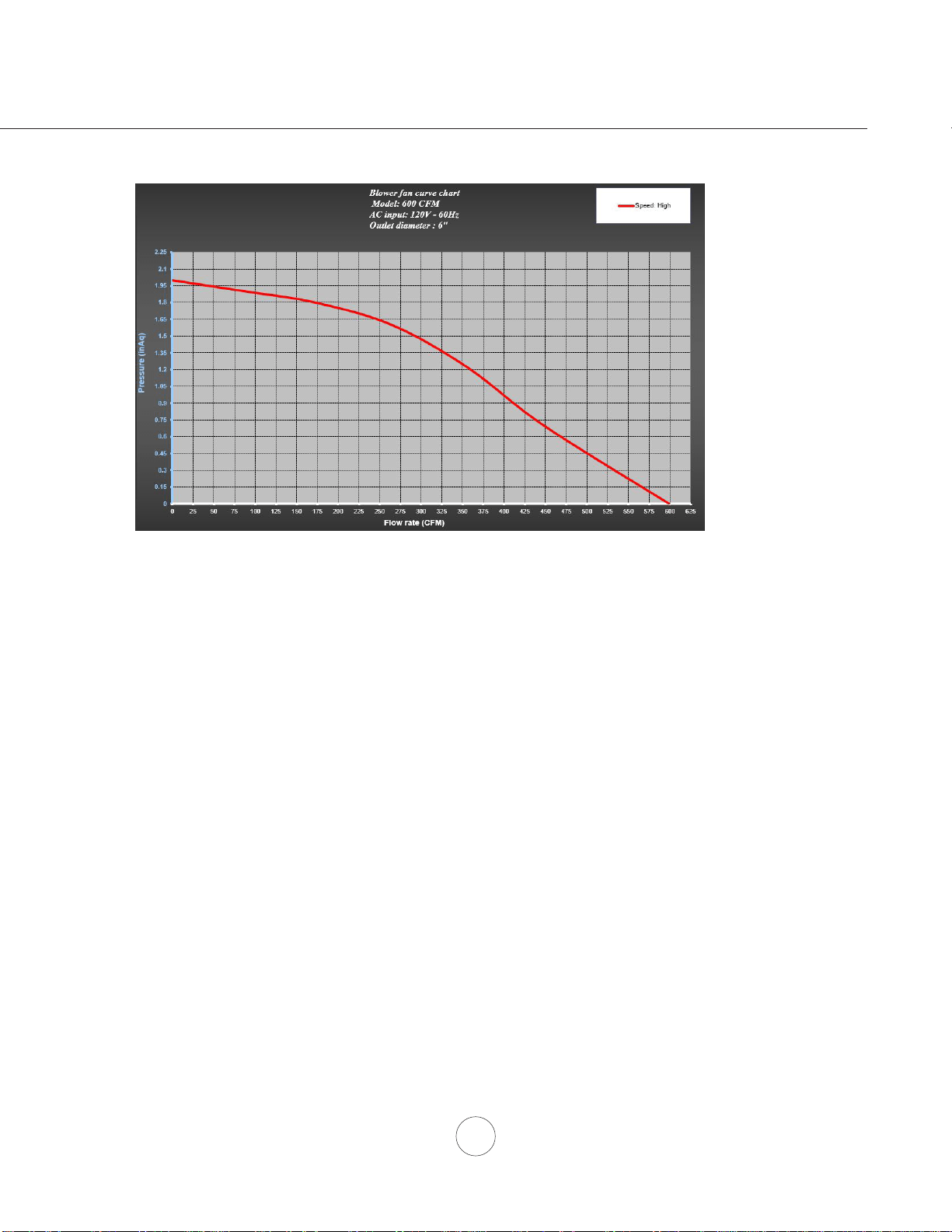
19
Tableau De Rendement Du Ventilateur
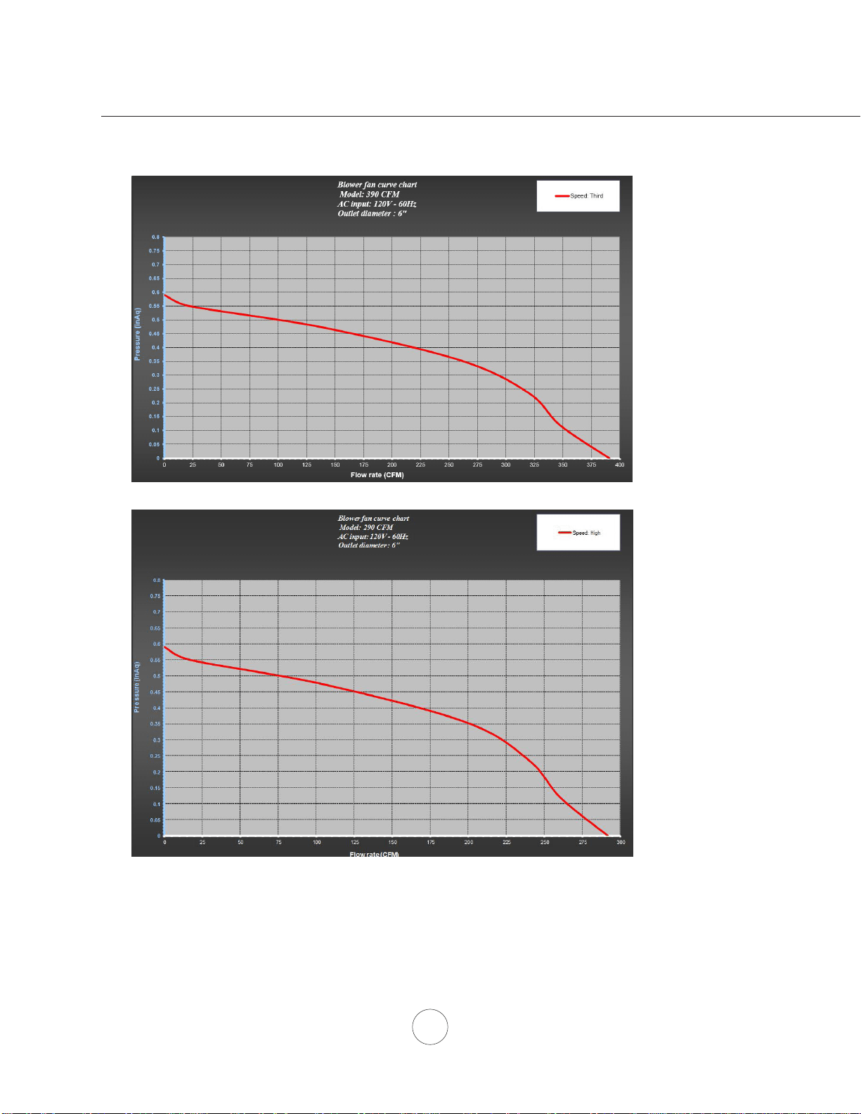
20
www.zephyronline.com
Tableau De Rendement Du Ventilateur
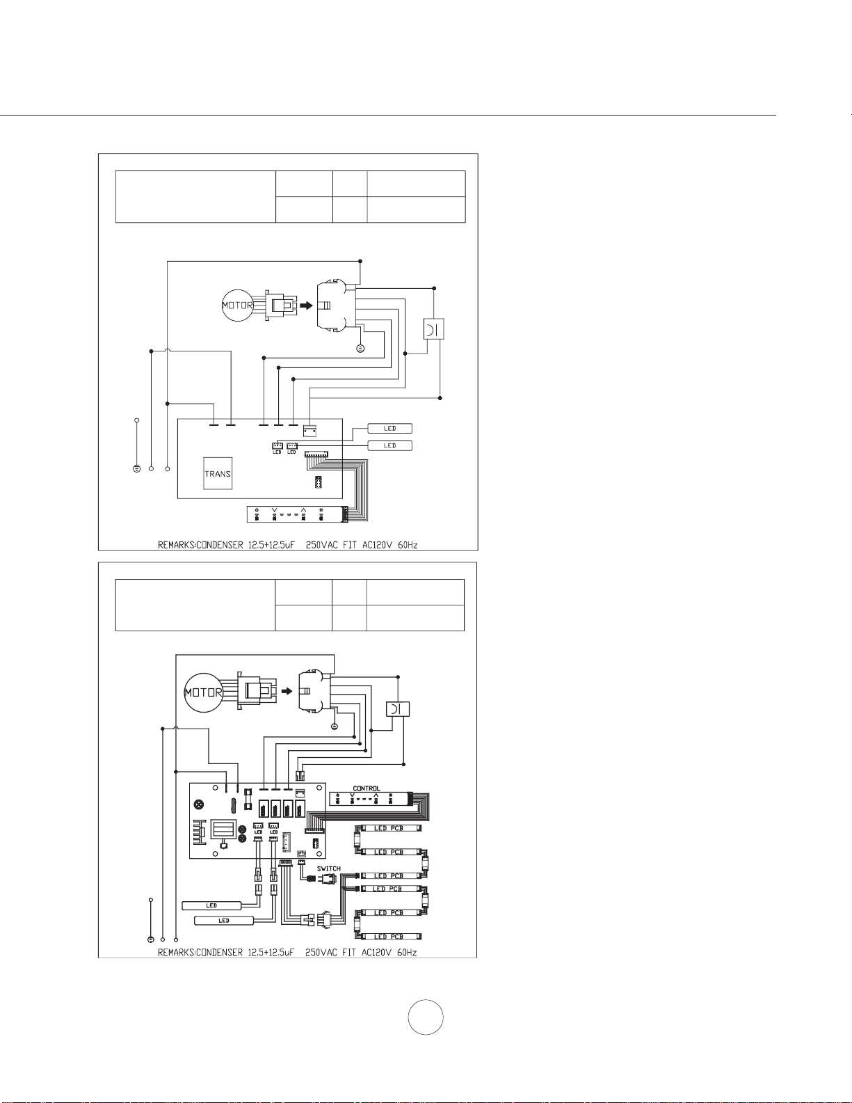
21
6FKpPD'H&kEODJH
ZAZ, ZRM
VOLTS HZ MAX. AMPS
120 60 4
Schéma De Câblage
BLANC
ROUGE
JAUNE
GRIS
BRUN
BLEU
ROUGE
JAUNE
JAUNE
VERTE
CORPS
BLEU
BRUN
GRIS
JAUNE
BLANC
NOIR/BLANC
CORPS
VERTE
NOIR
BLANC
Consommation montré pour défaut de
FRQ¿JXUDWLRQGXYHQWLODWHXU&)0
ZLC
VOLTS HZ MAX. AMPS
120 60 4
5A 250V AC
A C 120V
ZLC -E 42 B X - P
Schéma De Câblage
ROUGE
JAUNE
GRIS
BRUN
BLEU
ROUGE
BLANC
VERTE
CORPS
JAUNE
JAUNE
JAUNE
JAUNE
BLEU
BRUN
NOIR
NOIR/BLANC
BLANC
CORPS
VERTE
NOIR
BLANC
ACT 390 CFM - Ventilateur Max. @ 2.3A
ACT 290 CFM - Ventilateur Max. @ 1.9A
ACT 390 CFM - Ventilateur Max. @ 2.3A
ACT 290 CFM - Ventilateur Max. @ 1.9A
Consommation montré pour défaut de
FRQ¿JXUDWLRQGXYHQWLODWHXU&)0

22
www.zephyronline.com
DESCRIPTION N
O
DE PIÈCE
=$=3LqFHVHWGHVDFFHVVRLUHV
)LOWUHjGHÀHFWXHUFKDTXH
Ensemble de reprise d’air ZRC-02AZ
Filtre à charbon de remplacement (chaque) Z0F-C091
Ensemble de prolongement de recouvrement de conduit Z1C-00AZ
)LOWUHGHGpÀHFWHXUK\EULGH)LOWUHV =)%
=/&3LqFHVHWGHVDFFHVVRLUHV
)LOWUHjGHÀHFWXHUFKDTXH
Ensemble de reprise d’air ZRC-00LC
Filtre à charbon de remplacement (chaque) Z0F-C092
Ensemble de prolongement de recouvrement de conduit Z1C-00LC
=503LqFHVHWGHVDFFHVVRLUHV
)LOWUHjGHÀHFWXHUFKDTXH
Ensemble de reprise d’air, ZRM-E36DS ZRC-02RM
Ensemble de reprise d’air, ZRM-E42DS ZRC-01RM
Filtre à charbon de remplacement (chaque) Z0F-C002
Ensemble de prolongement de recouvrement de conduit Z1C-01RM
Pour commander des pièces, visitez-nous en ligne au www.zephyronline.com ou communiquez avec nous
par téléphone au 1-888-880-8368
Listes des pièces et des accessoires

23
Garantie
AGRAFEZ VOTRE REÇU ICI
POUR OBTENIR DU SERVICE SOUS GARANTIE OU POUR TOUTE QUESTION LIÉE À L’ENTRETIEN,
veuillez communiquer avec nous au 1-888-880-8368
Zephyr Ventilation, LLC (désigné aux présentes sous le nom de « nous ») garantit au premier acheteur (désigné aux
présentes sous le nom de « vous » ou « votre ») de produits Zephyr (les « Produits ») que lesdits produits sont exempts
de défauts de fabrication ou de main-d’œuvre selon les conditions suivantes :
Garantie de trois ans sur les pièces : Garantie de trois ans à partir de la date d’achat originale du Produit. Nous
fournirons sans frais les Produits ou les pièces (y compris les ampoules LED, le cas échéant) de remplacement qui com-
portaient des défauts de fabrication. Nous pourrions choisir, à notre seule discrétion, de réparer ou de remplacer des
pièces avant de prendre la décision de remplacer le Produit.
Garantie limitée d’un an sur la main-d’œuvre : Garantie d’un an à partir de la date d’achat originale du Produit. Nous
couvrirons sans frais les frais de main-d’œuvre afférents à la réparation du Produit ou des pièces de remplacement qui
comportaient des défauts de fabrication. Un an après la date d’achat originale, vous serez responsable de tous les frais
de main-d’œuvre associés à la présente garantie.
Exclusions de la garantie : Cette garantie ne couvre que la réparation ou le remplacement, à notre gré, de pièces ou
de Produits défectueux et ne couvre aucun autre coût afférent aux Produits, dont, sans s’y limiter, les frais liés : (a) à
l’entretien normal des Produits et au remplacement des pièces consommables, comme les fluorescent, incandescence
ou halogèneampoules, les filtres métalliques, les filtres à charbon et les fusibles; (b) à tout Produit ou pièce ayant été
endommagé durant le transport ou étant le résultat d’un mauvais usage, d’une négligence, d’un accident, d’une installa-
tion incorrecte ou ne respectant pas les notices d’installation recommandées, d’un entretien ou d’une réparation inap-
proprié (dont ne nous sommes pas responsables); (c) à une utilisation commerciale ou ne correspondant pas à
l’utilisation pour laquelle les Produits sont conçus; (d) à l’usure naturelle du fini, à l’usure due à un entretien inadéquat,
à l’utilisation de produits nettoyants corrosifs ou abrasifs, de tampons nettoyeurs et de produits de nettoyage pour le
four; (e) aux éclats, entailles ou fissures résultant d’un abus ou d’une mauvaise utilisation du Produit; (f) aux déplace-
ment d’un technicien de service à votre domicile pour vous montrer comment utiliser les Produits; (g) aux dommages
causés par un accident, un incendie, une inondation, un cas fortuit; ou (h) Les installations personnalisées ou modifica-
tions qui ont un impact maintenabilité du Produit. Si vous vous trouvez à l’extérieur du territoire que nous desservons,
des frais supplémentaires pourraient s’appliquer pour la livraison des produits à nos points de service désignés pour une
réparation sous garantie ou vous pourriez avoir à débourser les frais de déplacement du technicien à votre domicile pour
que le Produit soit réparé, enlevé ou réinstallé. Un an après la date d’achat originale du Produit, vous êtes également
responsable de tous les frais de main-d’œuvre associés à la présente garantie.
Restrictions de la garantie. NOTRE OBLIGATION DE RÉPARER OU DE REMPLACER, À NOTRE GRÉ, LE PRODUIT
CONSTITUE VOTRE SEUL ET UNIQUE RECOURS SOUS LA PRÉSENTE GARANTIE. NOUS NE NOUS PORTONS
PAS RESPONSABLES POUR TOUT DOMMAGE INDIRECT, ACCESSOIRE OU PARTICULIER RÉSULTANT OU AYANT
UN LIEN AVEC L’UTILISATION OU LE RENDEMENT DES PRODUITS. LES GARANTIES EXPRESSES DE LA SEC-
TION PRÉCÉDENTE SONT EXCLUSIVES ET TIENNENT LIEU DE TOUTE AUTRE GARANTIE EXPRESSE. PAR LES
PRÉSENTES, NOUS REJETONS ET EXCLUONS TOUTE AUTRE GARANTIE EXPRESSE POUR LES PRODUITS ET
TOUTES LES GARANTIES TACITES PRÉVUES PAR LA LOI, DONT CELLES RELATIVES À LA QUALITÉ
MARCHANDE OU À L'ADÉQUATION DU PRODUIT POUR UNE UTILISATION PARTICULIÈRE. Certains États ou
provinces n’autorisent pas les restrictions sur la durée d’une garantie implicite ou l’exclusion ou la restriction des dom-
mages indirects ou accessoires; par conséquent, les exclusions et restrictions mentionnées ci-dessus pourraient ne pas
s’appliquer à votre cas. Dans la mesure où une loi applicable interdit l’exclusion de garanties implicites, la durée de
toute garantie implicite applicable se limite à la période de deux ans décrite ci-dessus. L’unique objectif de toute descrip-
tion orale ou écrite est de présenter les Produits et celle-ci ne devrait pas être interprétée comme une garantie expresse.
Avant d’utiliser ou de permettre l’utilisation des Produits, vous devrez déterminer si les Produits conviennent aux utilisa-
tions prévues et vous devrez assumer tout risque et toute responsabilité relatifs à ces utilisations. Nous nous réservons
le droit d’utiliser des pièces reconstruites ou remises à neuf pour remplacer l’une des fonctionnalités dans le cadre de
la présente garantie ou de l’une des parties de la présente garantie. L’acheteur original ne peut transférer la présente
garantie et celle-ci n’est valide qu’aux États-Unis et au Canada.
Pour obtenir du service sous la garantie : Pour avoir droit à du service sous garantie, vous devez : (a) nous avertir
en utilisant l’adresse ou le numéro de téléphone inscrit ci-dessous dans les soixante jours suivant la détection du défaut;
(b) donner le numéro du modèle, le numéro d’identification de la pièce ainsi que le numéro de série; et (c) décrire la
nature de tout défaut de la pièce ou du Produit. Au moment de faire la demande de service sous garantie, vous devrez
présenter votre preuve d’achat et la preuve de la date d’achat originale. Si nous déterminons que les exclusions de la
garantie énumérées ci-dessus s’appliquent ou si vous vous trouvez dans l’incapacité de nous fournir la documentation
nécessaire pour obtenir du service, vous serez responsable de tous les frais d’expédition, de déplacement, de
main-d’œuvre ou de tout autre coût afférent au service.
Veuillez consulter notre site Web au www.zephyronline.com pour savoir si des révisions ont été apportées à la garantie.
Zephyr Ventilation Service Department, 2277 Harbor Bay Parkway, Alameda, CA 94502 1-888-880-8368
Garantie limitée
AUG14.0401
Une preuve de la date d’achat originale
est nécessaire pour obtenir du service
lorsque le produit est sous garantie

24
www.zephyronline.com
ENREGISTRMENT DU PRODUIT
Nous vous félicitons d’avoir acheté une
hotte Zephyr. Veuillez prendre un moment
pour enregistrer votre nouvelle hotte au
www.zephyronline.com/registration
Zephyr Ventilation | 2277 Harbor Bay Pkwy. | Alameda, CA 94502 | 1.888.880.8368
Cet enregistrement rapide est utile à
bien des égards.
C’EST IMPORTANT
Il assure la couverture de votre garantie si vous
avez besoin de service après-vente.
À des fins d’assurance, il permet de confirmer
que vous êtes le propriétaire.
Il vous permet de recevoir des avis concernant
des modifications ou des rappels de produits.