Loading ...
Loading ...
Loading ...
Page 18
SERVICE (cont.)
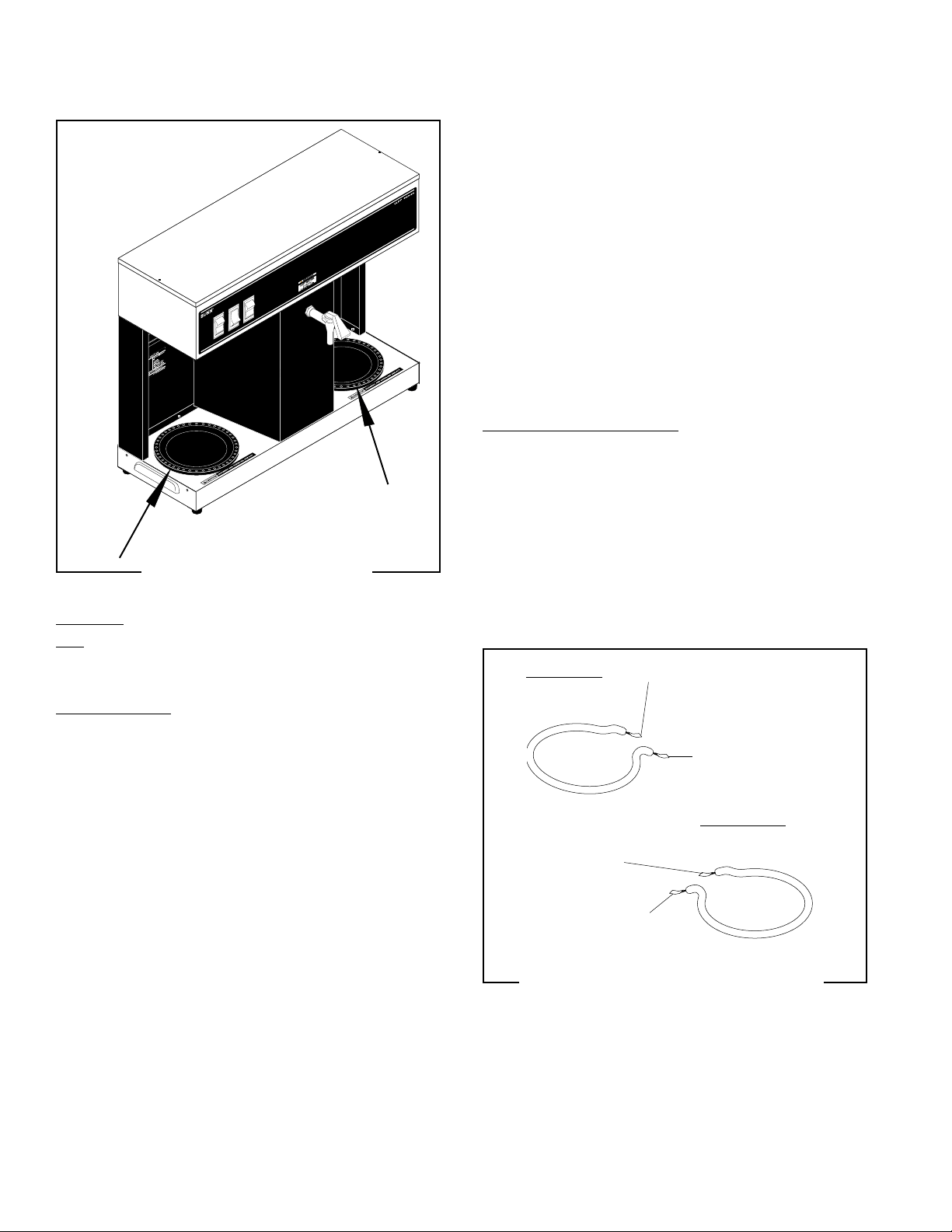
DECANTER WARMERS
FIG. 8 DECANTER WARMERS
P1956.40
Left Warmer
Right Warmer
WHI/VIO to On/Left Switch
WHI to Right Warmer
WHI to Cordset
BRN/BLK to Right
Switch
WHI to On/Left Switch
WHI to Left Warmer
FIG. 9 WARMER ELEMENT TERMINALS
P1982
Location:
The decanter warmers are located in the base of
the brewer.
Test Procedure:
1. Disconnect the brewer from the power source
and remove the three #4-40 screws attaching the
suspect warmer.
2. Bring the warmer assembly out the top of the
base.
3. Disconnect both wires from the warmer. Make sure
that the wire ends do not touch any metal surface
of the brewer.
4. With a voltmeter, check the voltage across the
two wires removed from the warmer when the
appropriate warmer switch (on/left or right) is in
the upper position. The voltage must be 120 volts
ac.
10179 060100
5. Connect the crewer to the power source.
If voltage is present as described, proceed to #6.
If voltage is not present as described, refer to the Wir-
ing Diagram and check the brewer wiring harness.
6. Disconnect the brewer from the power source.
7. Check for continuity across the two terminals on
the warmer.
If continuity is present as described, reconnect the
wires to the terminals, the warmer is operating prop-
erly.
If continuity is not present as described, replace the
warmer.
Removal and Replacement
1. Remove the three #4-40 slotted-head screws
holding the warmer to the brewer base.
2. Bring the warmer out the top of the base.
3. Disconnect both wires from the warmer.
4. Refer to FIG. 9 when reconnecting the wires and
orienting the warmers.
5. Place the warmer into the base and securely attach
it using the three #4-40 screws.
Loading ...
Loading ...
Loading ...