Loading ...
Loading ...
Loading ...
9
2
5
6
3
4
21
6
5
6
3
4
21
6
1 2
3 4
5 6
12 1/16”
4 9/16”
´
>
´
24”
24”
4 9/16”
7.2.1
2.1
2.1
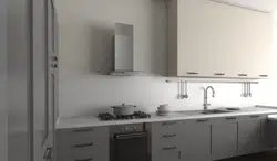
Draw a horizontal line where indicated above the hob.
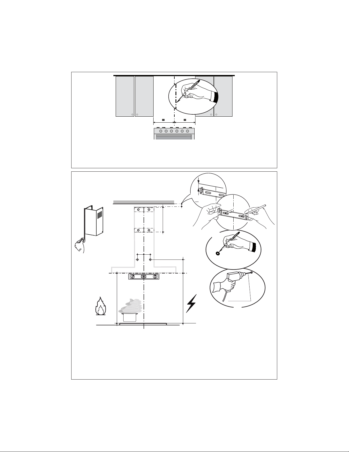
3ODFHDEUDFNHWRQWKHZDOODVVKRZQDERXW" from the ceiling or upper limit, aligning the center
(notch) with the vertical reference line and mark the wall at the centers of the holes in the bracket.
3ODFHWKHVHFRQGEUDFNHWRQWKHZDOODVVKRZQEHORZWKH¿UVWEUDFNHWDWWKHKHLJKWRIWKH
upper chimney section supplied and aligning the center (notch) with the vertical line.
0DUNWKHZDOODWWKHFHQWHUVRIWKHKROHVLQWKHEUDFNHWDQGPDUNWKHSRLQWDQGIRUWKH+RRG%RG\
LQVWDOODWLRQDVVKRZQ" from the horizontal line and 4 " from the vertical line).
'ULOO¡KROHVDWDOOWKHFHQWHUSRLQWVPDUNHGSRLQWDVVKRZQ
1
Draw a vertical line on the supporting wall as high as practical, at the center of the area in which
the hood will be installed.
'UDZDKRUL]RQWDOOLQHDWZKHUHWKHERWWRPHGJHRIWKHKRRGZLOOEHORFDWHGDVLQGLFDWHGLQWKH¿JXUH
that is a minimum of 24" above cooking surface.
Loading ...
Loading ...
Loading ...