GLAS36SS300-B
GLAS30SS300-B
GLAS36SS600-B
GLAS30SS600-B
Installation Instructions
Use and Care Information
Instructions d'installation
Utilisez et d'entretien
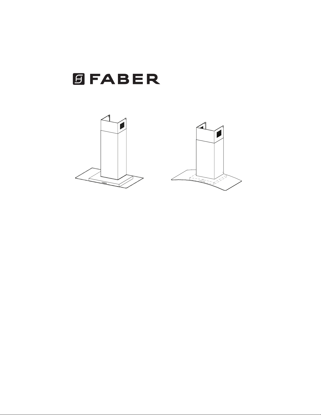
GLASSY 30"
GLASSY 36"
TRATTO 30"
TRATTO 36"
TRAT30SS600-B
TRAT36SS600-B

2
READ AND SAVE THESE INSTRUCTIONS BEFORE YOU START
INSTALLING THIS RANGEHOOD
WARNING: - TO REDUCE THE RISK OF A RANGE TOP GREASE FIRE:
a) Never leave surface units unattended at high settings. Boilovers cause smoking and
greasy spillovers that may ignite. Heat oils slowly on low or medium setting.
A KV@XRSTQMGNNC.-VGDMBNNJHMF@SGHFGGD@SNQVGDMl@LADHMFENNCHD"QDODR
Suzette, Cherries Jubilee, Peppercorn Beef Flambé).
c) Clean ventilating fans frequently. Grease should not be allowed to accumulate on fan
NQkKSDQ
d) Use proper pan size. Always use cookware appropriate for the size of the surface element.
WARNING: - TO REDUCE THE RISK OF INJURY TO PERSONS IN THE EVENT OF A
RANGE TOP GREASE FIRE, OBSERVE THE FOLLOWING*:
@2,.3'$1%+ ,$2VHSG@BKNRDkSSHMFKHCBNNJHDRGDDSNQLDS@KSQ@XSGDMSTQMNEESGDATQMDQ
!$" 1$%4+3./1$5$-3!41-2(ESGDl@LDRCNMNSFNNTSHLLDCH@SDKX$5 "4 3$
AND CALL THE FIRE DEPARTMENT.
b) NEVER PICK UP A FLAMING PAN - You may be burned.
c) DO NOT USE WATER, including wet dishcloths or towels - a violent steam explosion will
result.
d) Use an extinguisher ONLY if:
1. You know you have a Class ABC extinguisher, and you already know how to operate it.
3GDkQDHRRL@KK@MCBNMS@HMDCHMSGD@QD@VGDQDHSRS@QSDC
3GDkQDCDO@QSLDMSHRADHMFB@KKDC
8NTB@MkFGSSGDkQDVHSGXNTQA@BJSN@MDWHS
* Based on "Kitchen Firesafety Tips" published by NFPA
WARNING - TO REDUCE THE RISK OF FIRE OR ELECTRIC SHOCK, do not use this
fan with any solid-state speed control device.
WARNING - TO REDUCE THE RISK OF FIRE, ELECTRICAL SHOCK, OR INJURY TO
PERSONS, OBSERVE THE FOLLOWING:
1. Use this unit only in the manner intended by the manufacturer. If you have any
questions, contact the manufacturer.
2. Before servicing or cleaning unit, switch power off at service panel and lock the
service disconnecting means to prevent power from being switched on acciden-
tally. When the service disconnecting means cannot be locked, securely fasten a
prominent warning device, such as a tag, to the service panel.
CAUTION: For General Ventilating Use Only. Do Not Use To Exhaust Hazardous or
Explosive Materials and Vapors.
WARNING - TO REDUCE THE RISK OF FIRE, ELECTRICAL SHOCK, OR INJURY TO
PERSONS, OBSERVE THE FOLLOWING:
1. (MRS@KK@SHNM6NQJ MC$KDBSQHB@K6HQHMF,TRS!D#NMD!X0T@KHkDC/DQRNMR(M BBNQ-
dance With All Applicable Codes And Standards, Including Fire-Rated Construction.
2. 2TEkBHDMS@HQHRMDDCDCENQOQNODQBNLATRSHNM@MCDWG@TRSHMFNEF@RDRSGQNTFG
SGDlTDBGHLMDXNEETDKATQMHMFDPTHOLDMSSNOQDUDMSA@BJCQ@ESHMF%NKKNVSGD
heating equipment manufacturer's guideline and safety standards such as those
OTAKHRGDCAXSGD-@SHNM@K%HQD/QNSDBSHNM RRNBH@SHNM-%/ @MCSGD LDQHB@M
2NBHDSXENQ'D@SHMF1DEQHFDQ@SHNM@MC HQ"NMCHSHNMHMF$MFHMDDQR 2'1 $@MC
the local code authorities.
3
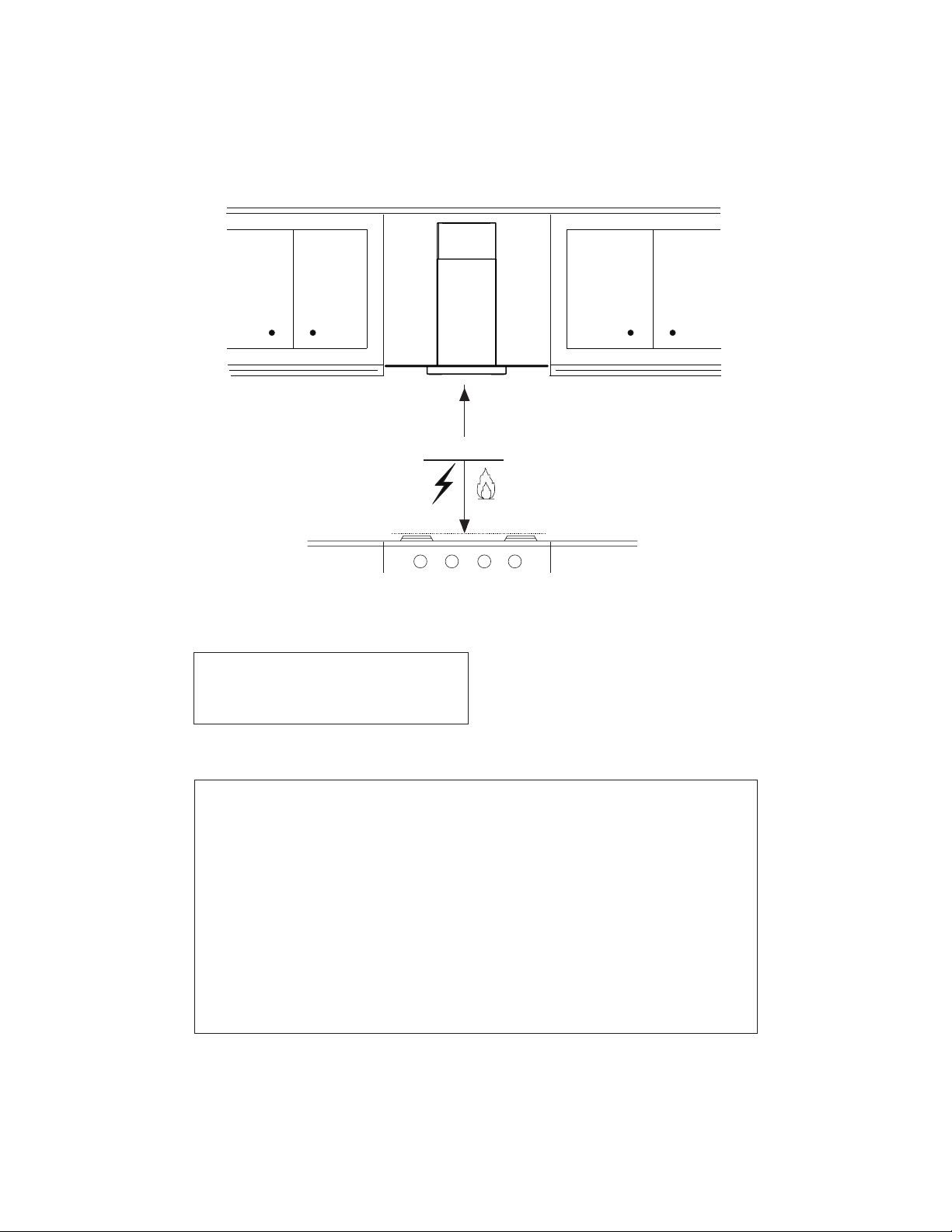
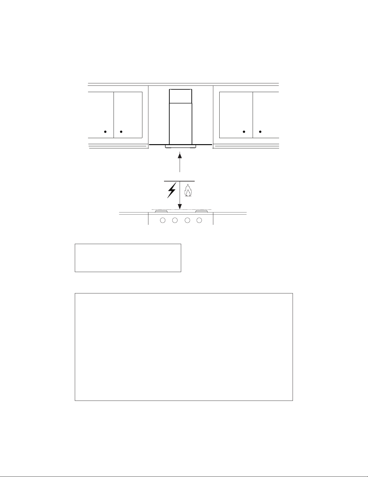
ALL WALL AND FLOOR OPENINGS WHERE THE RANGEHOOD IS INSTALLED MUST
BE SEALED.
This rangehood requires at least 24" of clearance between the bottom of the rangehood
and the cooking surface or countertop. This hood has been approved by UL at this distance from
the cooktop. Overhead cabinets on both sides of this unit must be a minimum of 18" above the
cooking surface or countertop. Consult the cooktop or range installation instructions given by
the manufacturer before making any cutouts. MOBILE HOME INSTALLATION The installation
of this rangehood must conform to the Manufactured Home Construction and Safety Standards,
Title 24 CFR, Part 3280 (formerly Federal Standard for Mobile Home Construction and Safety, Title
24, HUD, Part 280). See Electrical Requirements.
• Venting system MUST terminate outside the home.
• DO NOT terminate the ductwork in an attic or other enclosed space.
• DO NOT use 4" laundry-type wall caps.
• Flexible-type ductwork is not recommended.
• DO NOTNARSQTBSSGDkNVNEBNLATRSHNM@MCUDMSHK@SHNM@HQ
q%@HKTQDSNENKKNVUDMSHMFQDPTHQDLDMSRL@XQDRTKSHM@jQD
WARNING
!
Cold Weather installations
M@CCHSHNM@KA@BJCQ@ESC@LODQRGNTKCADHMRS@KKDCSNLHMHLHYDA@BJV@QCBNKC@HQkNV@MC@
nonmetallic thermal break should be installed to minimize conduction of outside temperatures as
part of the vent system. The damper should be on the cold air side of the thermal break. The break
should be as close as possible to where the vent system enters the heated portion of the house.
VENTING REQUIREMENTS
Determine which venting method is best for your application. Ductwork can extend either through the
wall or the roof.
3GDKDMFSGNESGDCTBSVNQJ@MCSGDMTLADQNEDKANVRRGNTKCADJDOSSN@LHMHLTLSNOQNUHCDDEjBHDMS
performance. The size of the ductwork should be uniform. Do not install two elbows together. Use
CTBSS@ODSNRD@K@KKINHMSRHMSGDCTBSVNQJRXRSDL4RDB@TKJHMFSNRD@KDWSDQHNQV@KKNQkNNQNODMHMF
around the cap.
Flexible ductwork is not recommended. Flexible ductwork creates back pressure and air turbulence
that greatly reduces performance.
,@JDRTQDSGDQDHROQNODQBKD@Q@MBDVHSGHMSGDV@KKNQkNNQENQDWG@TRSCTBSADENQDL@JHMFBTSNTSR
Do not cut a joist or stud unless absolutely necessary. If a joist or stud must be cut, then a supporting
frame must be constructed.
WARNING - To Reduce The Risk Of Fire, Use Only Metal Ductwork.
" 43(.-3NQDCTBDQHRJNEkQD@MCSNOQNODQKXDWG@TRS@HQADRTQDSNCTBS@HQNTSRHCDm#N
not vent exhaust air into spaces within walls or ceilings or into attics, crawl spaces, or garages.
3. When cutting or drilling into wall or ceiling, do not damage electrical wiring and
other hidden utilities.
4. Ducted fans must always be vented to the outdoors.
4
• Electrical ground is required on this rangehood.
• If cold water pipe is interrupted by plastic, nonmetallic gaskets or other materials, DO
NOT use for grounding.
• DO NOT ground to a gas pipe.
• DO NOT have a fuse in the neutral or grounding circuit. A fuse in the neutral or
grounding circuit could result in electrical shock.
q"GDBJVHSG@PT@KHjDCDKDBSQHBH@MHEXNT@QDHMCNTAS@RSNVGDSGDQSGDQ@MFDGNNCHR
properly grounded.
q%@HKTQDSNENKKNVDKDBSQHB@KQDPTHQDLDMSRL@XQDRTKSHM@jQD
WARNING
5
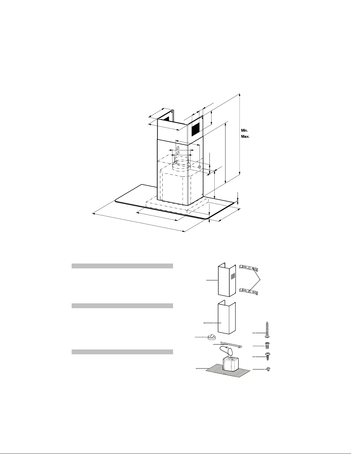
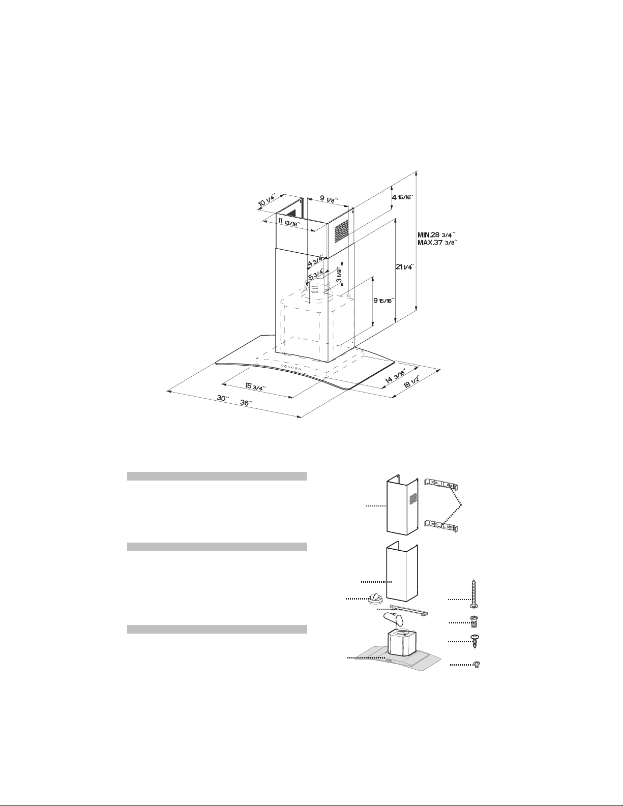
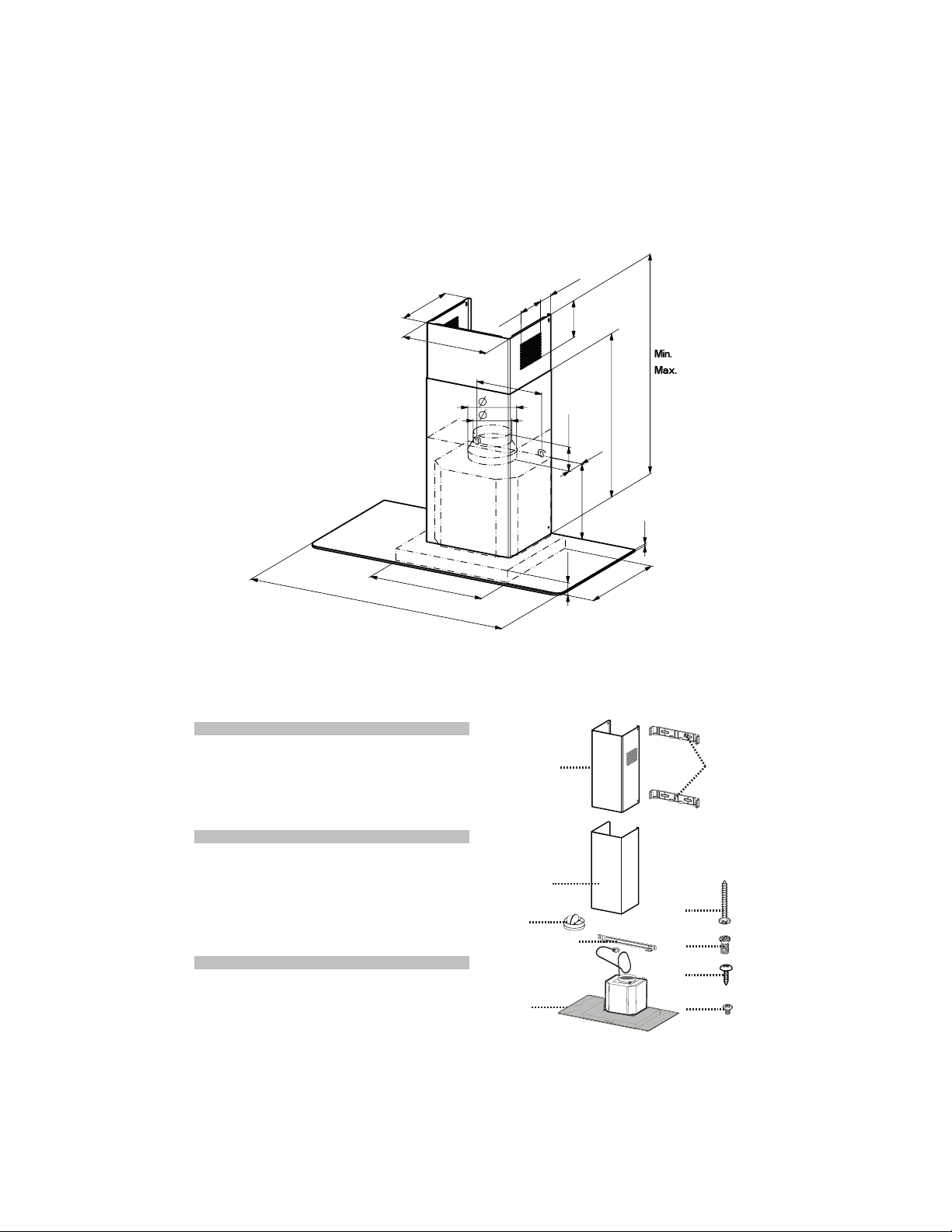
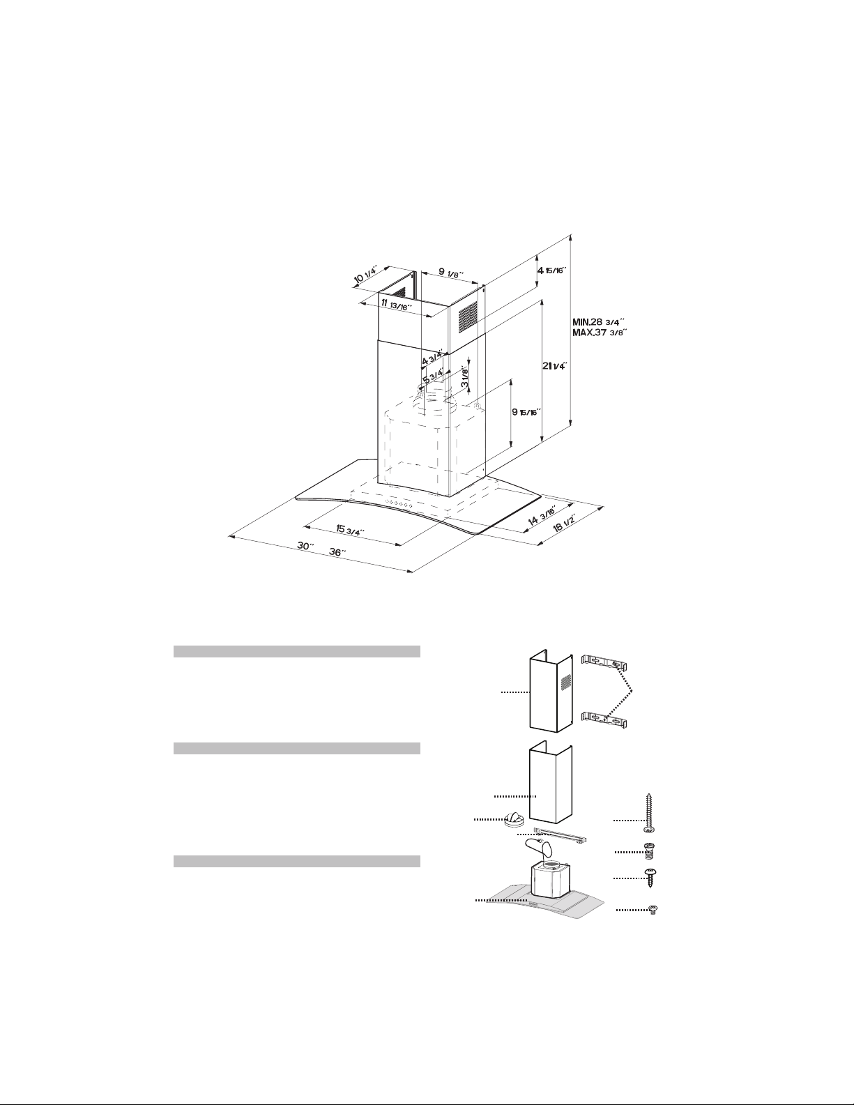
RANGEHOOD DIMENSIONS
30
’’ - 36’’
15
3/4
’’
11
13/16
’’
5
3/4
’’
4
3/4
’’
9
1/8
’’
4
15/16
’’
3-
15/16
’’
14
3/16
’’
’’
6
1
/
5
1
4
’
’
4
/
1
12
’
’
4
/
3
82
’
’
8
/
3
73
’’
6
1
/
5
1
9
’’
8
/
1
3
’’4/1
’
’
6
1
/
7
1
2
9/16
’’
10
1/4
’’
1
2.2
2.1
10
7.2.1
12a
12b
12c
7.3
12d
MAIN PARTS
Components
Ref. Qty. Product Components
1 1 Hood Body, complete with: Con-
trols, Light, Filters, Blower.
2 1 Telescopic Chimney comprising:
2.1 1 Upper Section
2.2 1 Lower Section
10 1 Damper ø 5 7/8"
Ref. Qty. Installation Components
7.2.1 2 Upper Chimney Section Fixing
Brackets
7.3 1 Cooker Hood Fixing Brackets
12a 4 Screws 3/16" x 1 3/4"
12b 4 Screws 1/8" x 3/8"
12c 2 Screws
12d 2 Screws 1/8" x 3/8"
Qty. Documentation
1 Instruction Manual
GLASSY 30" GLASSY 36"
6
RANGEHOOD DIMENSIONS
TRATTO 30" TRATTO 36"
MAIN PARTS
Components
Ref. Qty. Product Components
1 1 Hood Body, complete with: Con-
trols, Light, Filters, Blower.
2 1 Telescopic Chimney comprising:
2.1 1 Upper Section
2.2 1 Lower Section
10 1 Damper ø 5 7/8"
Ref. Qty. Installation Components
7.2.1 2 Upper Chimney Section Fixing
Brackets
7.3 1 Cooker Hood Fixing Brackets
12a 4 Screws 3/16" x 1 3/4"
12b 4 Screws 1/8" x 3/8"
12c 2 Screws
12d 2 Screws 1/8" x 3/8"
Qty. Documentation
1 Instruction Manual
2.2
2.1
10
7.2.1
12b
12c
7.3
1
12d
12a
7
Available Accessories
- Direct Connect Wiring Box sku # number: - WIREBOX
+LJK&HLOLQJ&KLPQH\.LW8SSHUDQG/RZHU&KLPQH\)OXHWRUHSODFHWKHRULJLQDOÀXHV
WR¿WXSWRFHLOLQJVVNX+,*+
- Ductless Kit - Includes Ductless Diverter, Charcoal Filters - sku# DUCT4
- 6" Make-Up Air Damper Kit - MUDAMPER6
- 8" Make-Up Air Damper Kit - MUDAMPER8
- CFM Reducer Kit - CFMRED
- Activated Charcoal Filter Accessory - sku# FILTER2
- Wireless Remote Control Accessory - REMCTRL
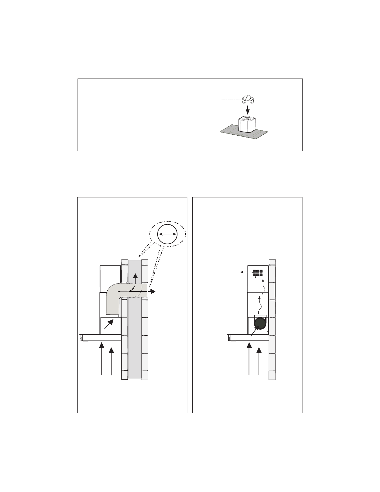
Parts needed
- 6" Round Metal ductwork
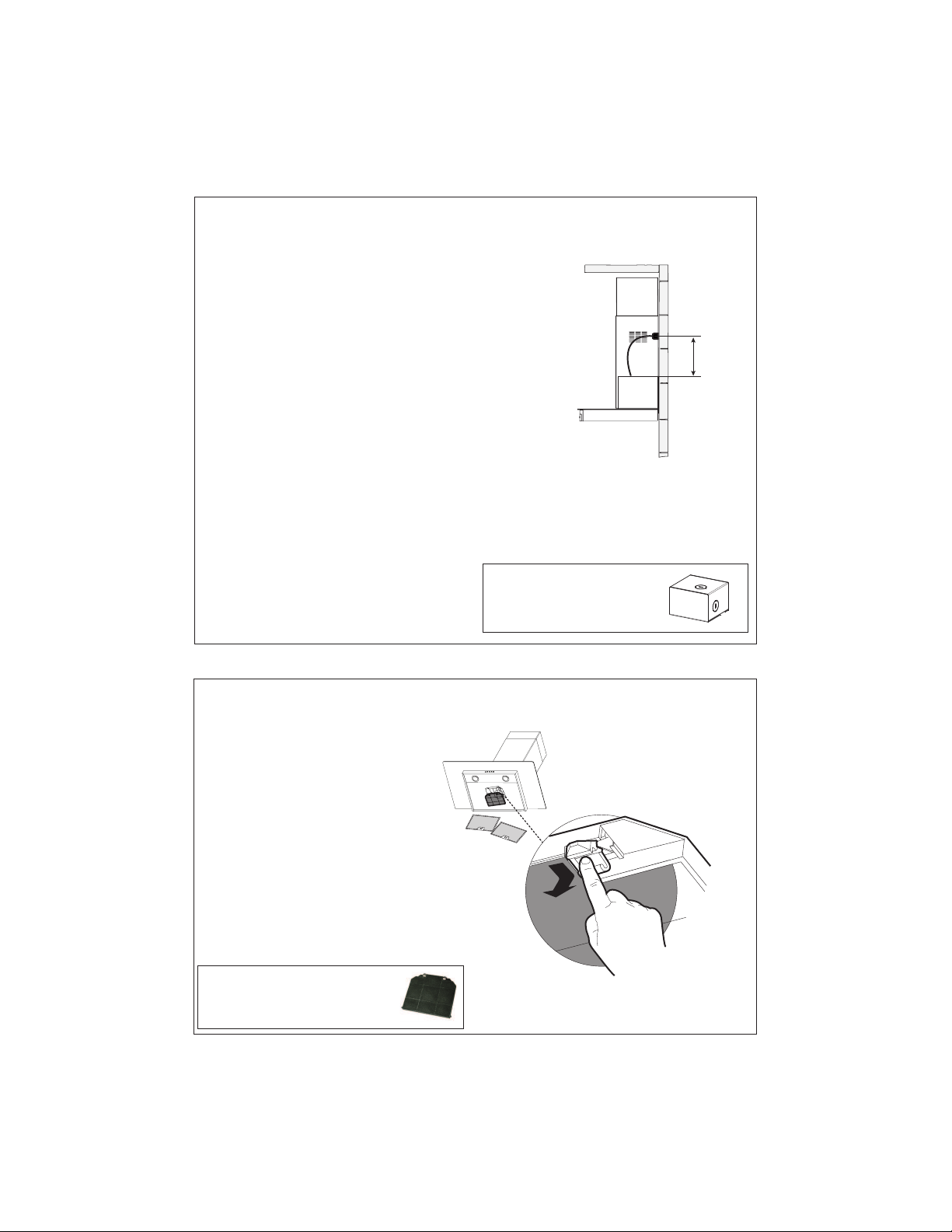
Min. 24"

8
H
I
Install Damper that is included with the Hood
before connecting to the ductwork.
Only for Ducted Venting Installation
Choose your ducting method
Non Ducted - Recirculation OptionDucted Venting Options Installation
Requires
purchase of
Activated
Charcoal
Accessory
Horizontal
Vertical
6 "

9
2
5
6
3
4
21
6
5
6
3
4
21
6
1 2
3 4
5 6
12 1/16”
4 9/16”
´
>
´
24”
24”
4 9/16”
7.2.1
2.1
2.1
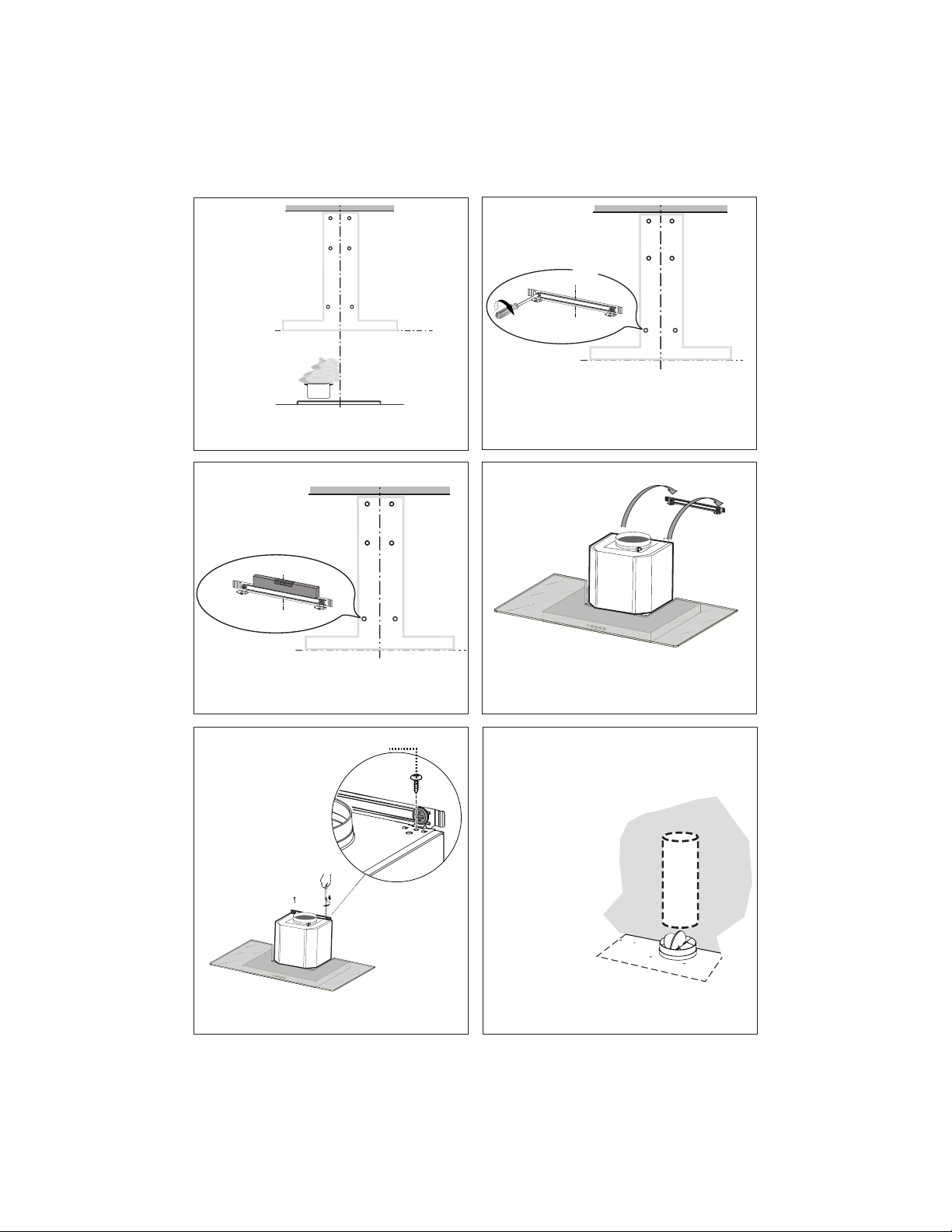
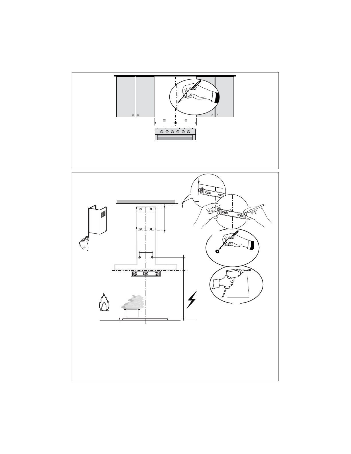
Draw a horizontal line where indicated above the hob.
3ODFHDEUDFNHWRQWKHZDOODVVKRZQDERXW" from the ceiling or upper limit, aligning the center
(notch) with the vertical reference line and mark the wall at the centers of the holes in the bracket.
3ODFHWKHVHFRQGEUDFNHWRQWKHZDOODVVKRZQEHORZWKH¿UVWEUDFNHWDWWKHKHLJKWRIWKH
upper chimney section supplied and aligning the center (notch) with the vertical line.
0DUNWKHZDOODWWKHFHQWHUVRIWKHKROHVLQWKHEUDFNHWDQGPDUNWKHSRLQWDQGIRUWKH+RRG%RG\
LQVWDOODWLRQDVVKRZQ" from the horizontal line and 4 " from the vertical line).
'ULOO¡KROHVDWDOOWKHFHQWHUSRLQWVPDUNHGSRLQWDVVKRZQ
1
Draw a vertical line on the supporting wall as high as practical, at the center of the area in which
the hood will be installed.
'UDZDKRUL]RQWDOOLQHDWZKHUHWKHERWWRPHGJHRIWKHKRRGZLOOEHORFDWHGDVLQGLFDWHGLQWKH¿JXUH
that is a minimum of 24" above cooking surface.
10
7
3
4
5
6
I = 6x
I = 6x
2X
12a
Installation screws provided must be secured
with wall plugs (purchase separately).
,QVHUWWKHWZRVFUHZVDVXSSOLHGZLWKWKHKRRG
into the Fixing Bracket as shown and do not
WLJKWHQ DOO WKH ZD\ WR ZDOO OHDYLQJ RI WKH
screw heads exposed.
Use a level to insure that Fixing Bracket is level and
then fully secure the two screws.
+RRN WKH KRRG ERG\ RQWR WKH KRRG ERG\ ¿[LQJ
bracket 7.3.
I = 6x
11
8
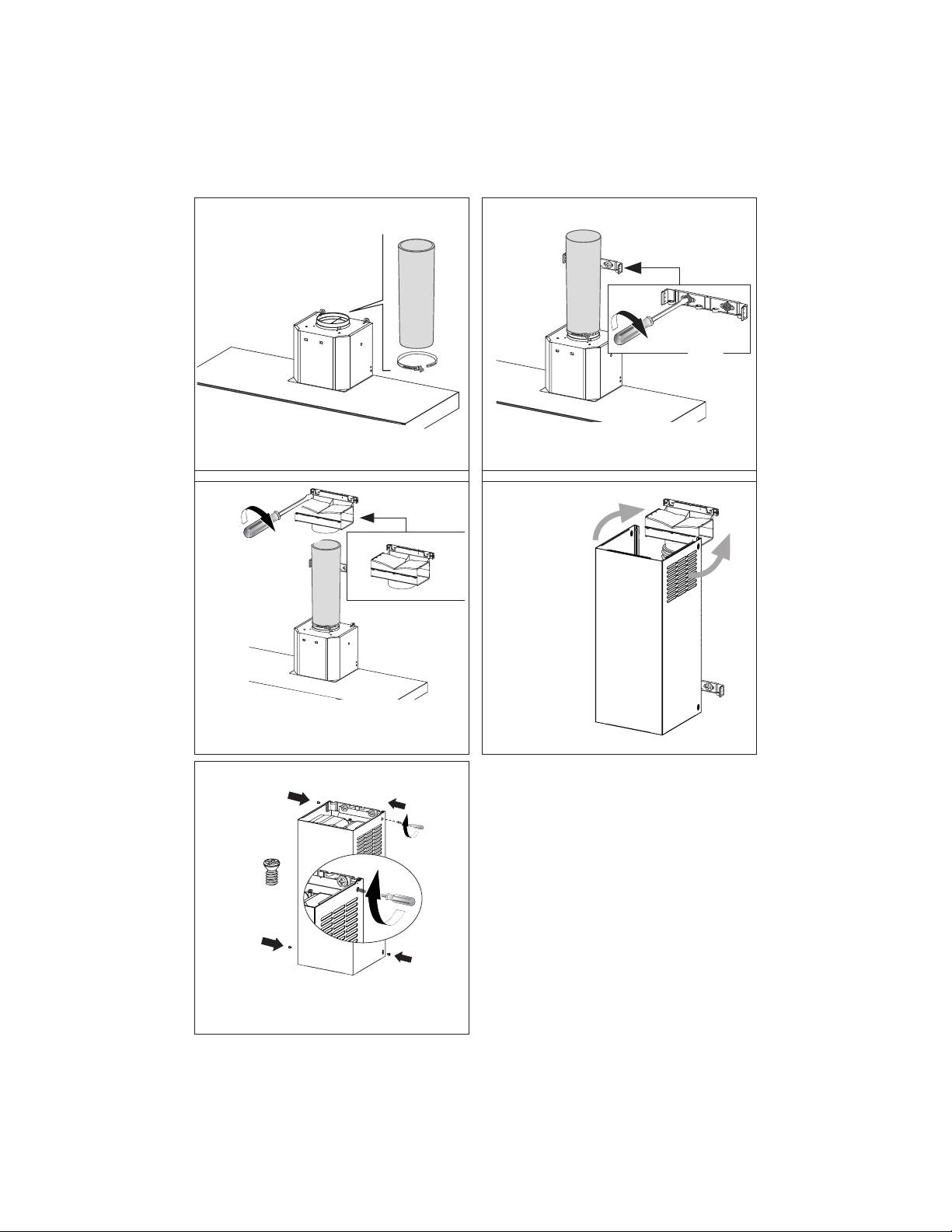
Install Roof or Wall
Cap purchased
separately. Con-
nect the 6" metal
ductwork to the
Roof or Wall Cap
and then attach
ductwork.
Vertical or Horizontal
Ducting Installation
12c
Tighten the 2 screws 12c as shown.
11
9
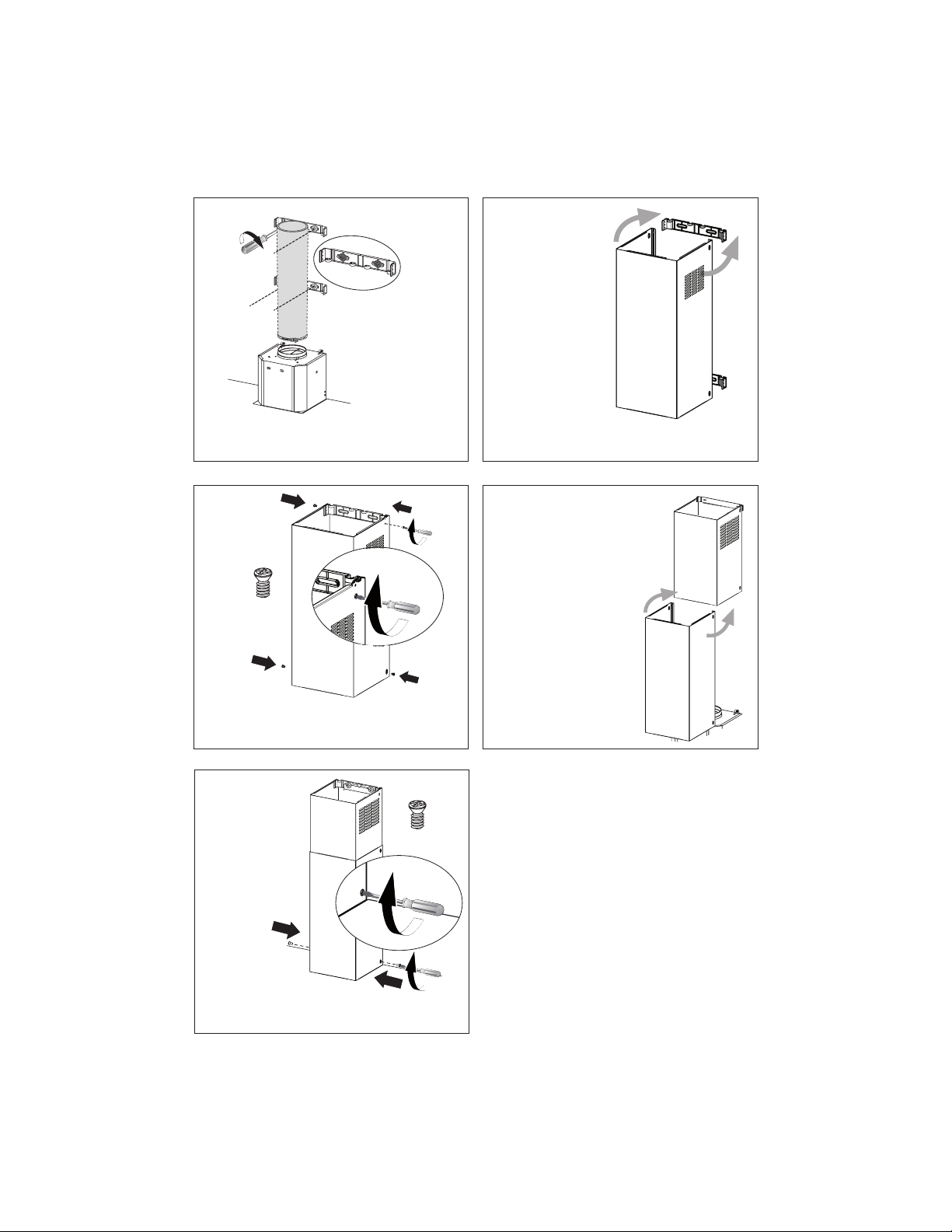
L = 4x
,QVWDOOWKH¿[LQJEUDFNHWVWRWKHPLGGOHDQG
XSSHUKROHVDQGVHFXUHZLWKVFUHZVDDVVKRZQ
10
11
2.1
N = 4x
12b
Slightly widen
the two sides
of the upper
chimney and
hook them
behind the
brackets 7.2.1,
making sure
that they are
well seated.
Secure the sides to the brackets by using the 4
screws 12b.
12a
13
Slightly widen the two
sides of the the lower
chimney hood and hook
them between
the upper section and the
wall, making sure that they
are properly housed.
Fix the the
lower chim-
ney hood
laterally to
the hood
body using
the 2 screws
12d supplied.
12
2.2
2.1
N = 2x
12d

12
16 17
18
2.1
Fix the Ductless Diverter with two screws 12a supplied
as shown.
Slightly widen
the two sides of
the upper chim-
ney and hook
them behind
the brackets
and connect to
the Ductless
Diverter, mak-
ing sure that
they are well
seated.
14 15
¡
12a
Only for the recirculation version, connect the hood
to the Air outlet.
Fix the lower Bracket 7.2.1 with WZRVFUHZVD
supplied as shown.
Non-Ducted Recirculation Option
N = 4x
12b
Secure the sides to the brackets by using the 4
screws 12b.

13
Direct Connect Wiring Box
Accessory sku # WIREBOX
(purchased separately)
ELECTRICAL INSTALLATION WITH CONNECTION
CABLE
*5281',1*,16758&7,216 7KLVDSSOLDQFH PXVW EH
grounded. In the event of an electrical short circuit, grounding
reduces the risk of electric shock by providing an escape
wire for the electric current. This appliance is equipped
with a cord having a grounding wire with a grounding plug.
The plug must be plugged into an outlet that is properly
installed and grounded.
:$51,1* ,PSURSHU JURXQGLQJ FDQ UHVXOW LQ D ULVN RI
electric shock.
&RQVXOWDTXDOL¿HGHOHFWULFLDQLIWKHJURXQGLQJLQVWUXFWLRQV
are not completely understood, or if doubt exists as to
whether the appliance is properly grounded.
Do not use an extension cord. If the power supply cord is
WRRVKRUWKDYHDTXDOL¿HGHOHFWULFLDQLQVWDOODQRXWOHWQHDU
the appliance.
ELECTRICAL INSTALLATION WITH
OPTIONAL WIRING BOX
For Permanent wiring Installation-Use only
with Listed rangehood Wiring Box kit
sku # WIREBOX, manufactured by Faber.
Max. 33 7/16”
19
For Non-Ducted Recirculation
Option
Required Activated Charcoal Filter
Accessory - sku # - FILTER2
(purchased separately)
Attach a
charcoal
¿OWHULQWKH
correct
position and
block it by
WKH¿[LQJ
hooks as
shown.
8QORFNWKH¿[LQJKRRNVWRZDUGVWKHEDFNRIWKH
insert hood) to remove.
14
N = 2x
12d
2.2
2.1
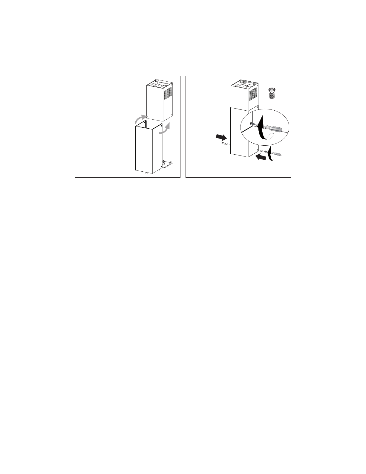
20 21
Slightly widen the two
sides of the the lower
chimney hood and hook
them between
the upper section and the
wall, making sure that they
are properly housed.
Fix the the
lower chim-
ney hood
laterally to
the hood
body using
the 2 screws
12d supplied.

15
USE AND CARE INFORMATION
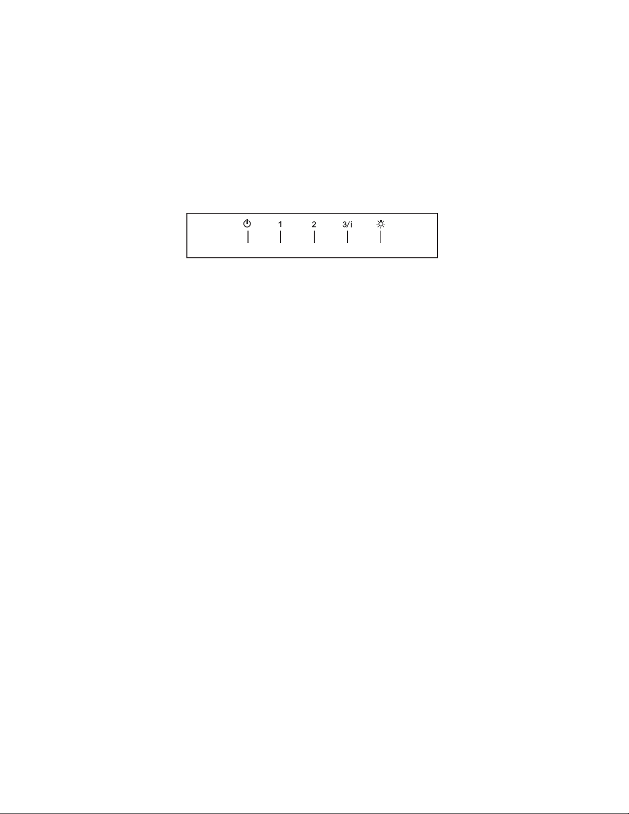
T1. Fan Off Button:Turn the blower Off. The fan can be operated by pressing any of the fan setting
buttons.
+ROGGRZQWKLVEXWWRQIRUVHFRQGVWRDFWLYDWH'HOD\2IIIXQFWLRQZKLFKZLOONHHSWKHIDQ2QIRU
minutes and automatically shut Off.
T2)DQ6HWWLQJV%XWWRQV/RZ6SHHG
T3)DQ6HWWLQJV%XWWRQV0HGLXP6SHHG
T4)DQ6HWWLQJV%XWWRQV+LJK6SHHG,QWHQVLYH6SHHG
+ROGGRZQWKHEXWWRQIRUVHFRQGVWRDFWLYDWHWKH,17(16,9(63(('ZKLFKLVWLPHGWRUXQIRU
PLQXWHV$WWKHHQGRIWKLVWLPHLWZLOODXWRPDWLFDOO\UHWXUQWRWKHVSHHGVHWEHIRUH6XLWDEOHWRGHDO
with maximum levels of cooking fumes.
L /LJKW%XWWRQ2Q'LP2IIVZLWFKIRUWKHOLJKWV3UHVVWKH/,*+7EXWWRQWRWXUQWKHOLJKWRQDJDLQWR
set the lights to dimmer, and again to turn off.
LT1 T2 T3 T4
For Best Results
6WDUWWKH UDQJHKRRG VHYHUDOPLQXWHV EHIRUHFRRNLQJ WR GHYHORSSURSHU DLUÀRZ$OORZ WKH
rangehood to operate for several minutes after cooking is complete to clear all smoke and
odors from the kitchen.

16
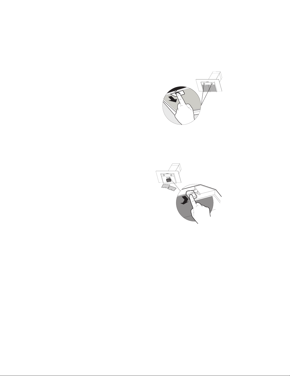
"KD@MHMFLDS@KFQD@RDkKSDQR
7KH¿OWHUVPXVWEHFOHDQHGHYHU\PRQWKVRIRSHUDWLRQRUPRUH
frequently for particularly heavy usage, and can be washed in
a dishwasher.
• Remove the Filters one at a time, pushing them towards
the back of the unit and at the same time pulling downward.
• Wash the Filters without bending them, and leave them to
GU\FRPSOHWHO\EHIRUHUHSODFLQJ,IWKHVXUIDFHRIWKH¿OWHU
changes colour as time goes by, this will have absolutely no
HIIHFWRQWKHHI¿FLHQF\RIWKH¿OWHULWVHOI
• Replace, taking care to ensure that the handle faces forwards.
Replacing Activated Charcoal Filter
7KH¿OWHULVQRWZDVKDEOHDQGFDQQRWEHUHJHQHUDWHGDQGPXVW
be replaced approximately every 4 months of operation, or more
frequently for particularly heavy usage.
• Remove the Filters one at a time, pushing them towards
the back of the unit and at the same time pulling downward.
• 5HPRYHWKHVDWXUDWHGFKDUFRDO¿OWHUE\UHOHDVLQJWKH¿[LQJ
hooks.
• )LWWKHQHZ¿OWHUDQGIDVWHQLWLQLWVFRUUHFWSRVLWLRQ
• Replace, taking care to ensure that the handle faces forwards.
Lighting Unit
• LED lights must be replaced by Faber factory authorized
service.
17
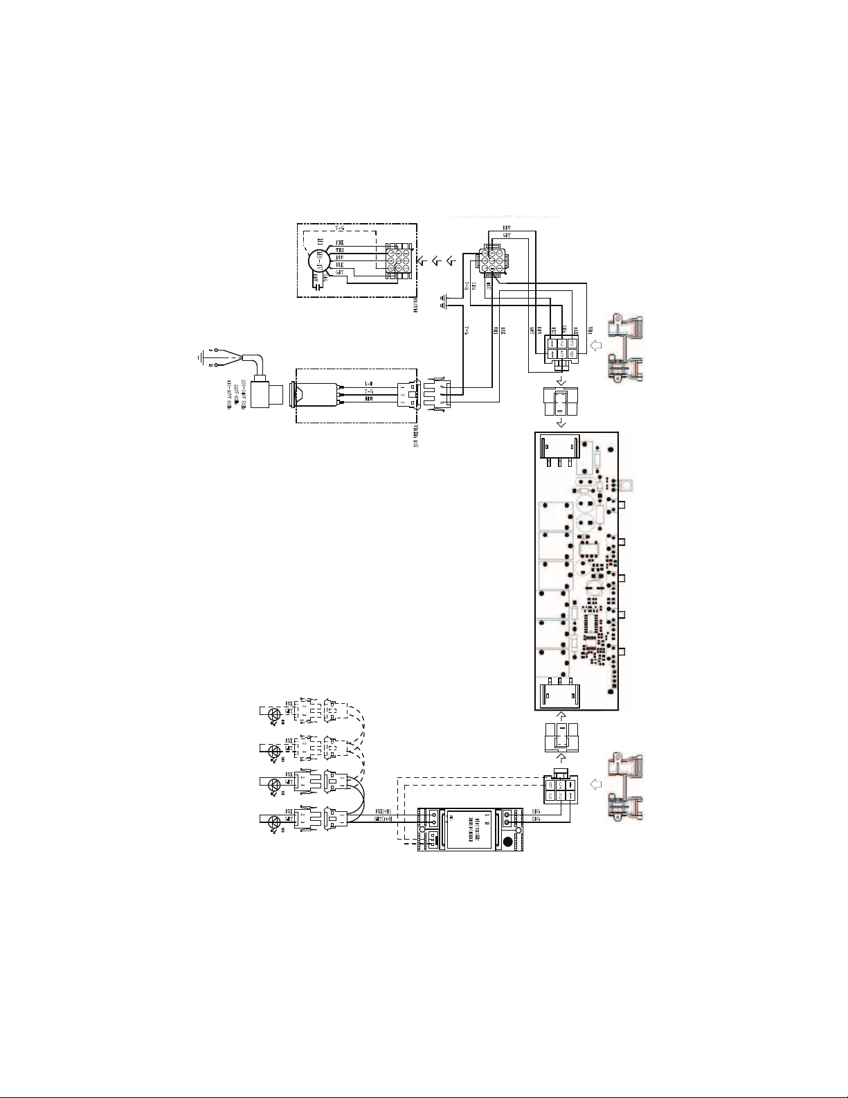
Wiring Diagram
991.0379.495 H90_285 r1
18
January 4, 2016
)$%(5&21680(5:$55$17<6(59,&(
All Faber products are warranted against any defect in materials or workmanship for the original purchaser
IRUDSHULRGRI\HDUIURPWKHGDWHRIRULJLQDOSXUFKDVHUHTXLUHVSURRIRISXUFKDVH7KLVZDUUDQW\FRYHUV
labor and replacement parts. Faber, at its option, may repair or replace the product or components
necessary to restore the product to good working condition. To obtain warranty service, contact the dealer
from whom you purchased the range hood, or the local Faber distributor. If you cannot identify a local Faber
GLVWULEXWRUFRQWDFWXVDWIRUWKHQDPHRIDGLVWULEXWRULQ\RXUDUHD
The following is not covered by Faber's warranty:
6HUYLFHFDOOVWRFRUUHFWWKHLQVWDOODWLRQRI\RXUUDQJHKRRGWRLQVWUXFW\RXKRZWRXVH\RXUUDQJHKRRGWR
replace or repair house fuses or to correct house wiring or plumbing.
6HUYLFHFDOOVWRUHSDLURUUHSODFHUDQJHKRRGOLJKWEXOEVIXVHVRUILOWHUV7KRVHFRQVXPDEOHSDUWVDUH
excluded from warranty coverage.
5HSDLUVZKHQ\RXUUDQJHKRRGLVXVHGIRURWKHUWKDQQRUPDOVLQJOHIDPLO\KRXVHKROGXVH
'DPDJHUHVXOWLQJIURPDFFLGHQWDOWHUDWLRQPLVXVHDEXVHILUHIORRGDFWVRI*RGLPSURSHULQVWDOODWLRQ
installation not in accordance with electrical or plumbing codes or Faber documentation, or use of products
not approved by Faber.
5HSODFHPHQWSDUWVRUUHSDLUODERUFRVWVIRUXQLWVRSHUDWHGRXWVLGHWKH8QLWHG6WDWHVRU&DQDGDLQFOXGLQJ
any non-UL or C-UL approved Faber range hoods.
6. Repairs to the hood resulting from unauthorized modifications made to the range hood.
7. Expenses for travel and transportation for product service in remote locations and pickup and delivery
charges. Faber range hoods should be serviced in the home.
7+,6:$55$17<'2(6127$//2:5(&29(5<2),1&,'(17$/25&216(48(17,$/'$0$*(6,1&/8',1*:,7+287
/,0,7$7,21',5(&7,1',5(&7,1&,'(17$/63(&,$/25&216(48(17,$/'$0$*(63(5621$/,1-85<:521*)8/
'($7+25/267352),76)$%(5:$55$17<,6/,0,7('727+($%29(&21',7,216$1'727+(:$55$17<3(5,2'
63(&,),('+(5(,1$1',6(;&/86,9((;&(37$6(;35(66/<63(&,),(',17+,6$*5((0(17)$%(5',6&/$,06$//
(;35(6625,03/,('&21',7,2165(35(6(17$7,216$1':$55$17,(6,1&/8',1*:,7+287/,0,7$7,21$1<
,03/,(':$55$17,(62)0(5&+$17$%,/,7<25),71(66)25$3$57,&8/$5385326(
.
This warranty gives you specific legal rights that may vary from state to state.
0RGHOBBBBBBBBBBBBBBBBBBBBBBBBBBBBBB6HULDOBBBBBBBBBBBBBBBBBBBBBBBBBBBBB

19
VEUILLEZ LIRE ET CONSERVER LA PRÉSENTE NOTICE AVANT DE
COMMENCER L'INSTALLATION DE LA HOTTE DE CUISINE
AVERTISSEMENT:-POUR RÉDUIRE LE RISQUE D'UN FEU DE GRAISSE SUR LA TABLE DE
"4(22.-Ů
a) Ne laissez jamais sans surveillance les éléments de la surface de cuisson à température élevée.
Les bouillonnements excessifs peuvent provoquer de la fumée et les débordements de graisse
ODTUDMSRfDMl@LLDQ+fGTHKDCNHSģSQDBG@TEEĢDKDMSDLDMSĒTMDSDLOĢQ@STQDA@RRDNTLNXDMMD
b) Assurez-vous de toujours mettre en marche le ventilateur de la hotte lorsque vous cuisinez
ĒSDLOĢQ@STQDĢKDUĢDNTOQĢO@QDYTMLDSRl@LAĢODWBQģODR2TYDSSDBDQHRDRITAHKĢATE
l@LAĢ
c) Nettoyez régulièrement les ventilateurs d'aspiration. Assurez-vous de ne pas laisser de la graisse
Rf@BBTLTKDQRTQKDUDMSHK@SDTQNTKDkKSQD
C4SHKHRDYSNTINTQRCDRONģKDRDSB@RRDQNKDRCDK@S@HKKD@OOQNOQHĢD4SHKHRDYSNTINTQRCDRTRSDMRHKDR
de cuisine de la taille adaptée à celle de l'élément chauffant.
5$13(22$,$-3Ů/.41/1Í5$-(1+$2!+$2241$2$-" 2#$%$4#$&1 (22$241+
3 !+$#$"4(22.-24(5$9+$21$".,, -# 3(.-224(5 -3$2Ů
a) ÉTOUFFEZ LES FLAMMES à l'aide d'un couvercle hermétique, d'une plaque à biscuits ou d'un
plateau métallique, puis éteignez le brûleur. FAITES ATTENTION AUX BRÛLURES. Si le feu ne
s'éteint pas immédiatement, QUITTEZ LES LIEUX ET APPELEZ LES POMPIERS.
b) NE PRENEZ JAMAIS UNE CASSEROLE EN FLAMME - Vous pourriez vous brûler.
c) N'UTILISEZ JAMAIS DE L'EAU, ni un linge à vaisselle ou un torchon mouillé, pour éteindre le feu.
Cela pourrait provoquer une violente explosion de vapeur.
C4SHKHRDYTMDWSHMBSDTQ4-(04$,$-3RHŮ
5NTRģSDRBDQS@HMPTfHKRf@FHSCfTMDWSHMBSDTQCDBK@RRD !"DSPTDUNTRBNMM@HRRDYAHDMRNM
mode d'emploi.
2. Le feu est de faible intensité et se limite à l'endroit où il a démarré.
3. Les pompiers ont déjà été appelés.
4MDUNHDCDRNQSHDRDSQNTUDCDQQHġQDUNTRODMC@MSPTDUNTRĢSDHFMDYKDRl@LLDR
#e@OQĠRKDFTHCDgŰ*HSBGDM%HQDR@EDSX3HORŰuOTAKHġO@QK@-%/ @TWÍS@SR4MHR
AVERTISSEMENT - POUR RÉDUIRE LE RISQUE D'INCENDIE OU DE CHOC ÉLECTRIQUE, n'utilisez
jamais ce ventilateur en association avec un dispositif de réglage de vitesse à semi-conducteurs.
AVERTISSEMENT - POUR RÉDUIRE LES RISQUES D'INCENDIE, DE CHOC ÉLECTRIQUE OU DE
!+$2241$".1/.1$++$1$2/$"3$9+$2(-2314"3(.-224(5 -3$2Ů
1. Utilisez cet appareil uniquement de la façon prévue par le fabricant. Pour toute question, com-
muniquez avec le fabricant.
2. Avant de procéder à l'entretien ou au nettoyage de l'appareil, coupez l'alimentation au niveau du
panneau électrique et verrouillez-le pour vous assurer que l'électricité n'est pas rétablie accidentel-
KDLDMS2fHKMfDRSO@RONRRHAKDCDUDQQNTHKKDQKDCHRONRHSHECfHMSDQQTOSHNMCDKf@KHLDMS@SHNM@EkBGDYCD
façon ferme et bien visible un avis de danger, par exemple à l'aide d'une étiquette sur le panneau.
33$-3(.-Ů#DRSHMĢĒTMTR@FDCDUDMSHK@SHNMFĢMĢQ@KDTMHPTDLDMS-fTSHKHRDYO@RBDCHRONRHSHE
pour l'aspiration de vapeurs ou de matériaux dangereux ou explosifs.
AVERTISSEMENT - POUR RÉDUIRE LES RISQUES D'INCENDIE, DE CHOC ÉLECTRIQUE OU DE
!+$2241$".1/.1$++$1$2/$"3$9+$2(-2314"3(.-224(5 -3$2Ů
1. +fHMRS@KK@SHNMDSKDAQ@MBGDLDMSĢKDBSQHPTDCNHUDMSģSQDQĢ@KHRĢRO@QTMSDBGMHBHDMPT@KHkĢDS
conformément à tous les codes et normes en vigueur, incluant ceux concernant la construction
à l'épreuve du feu.
2. kMCDF@Q@MSHQTMDBNLATRSHNMDSTMDĢU@BT@SHNM@CĢPT@SDRCDRF@YO@QKDRBNMCTHSDRCDK@
cheminée des appareils à combustion, une bonne aération est nécessaire pour éviter le refou-
lement. Respectez les lignes directrices fournies par le fabricant du matériel chauffant, ainsi que
KDRMNQLDRCDRĢBTQHSĢBNLLDBDKKDROTAKHĢDRO@QK@-@SHNM@K%HQD/QNSDBSHNM RRNBH@SHNM-%/
DSK@ LDQHB@M2NBHDSXENQ'D@SHMF1DEQHFDQ@SHNM@MC HQ"NMCHSHNMHMF$MFHMDDQR 2'1 $@TW
États-Unis, ainsi que les codes en vigueur dans votre région.

20
3. Lorsque vous faites une ouverture ou percez dans un mur ou le plafond, veillez à ne pas en-
CNLL@FDQKDRkKRĢKDBSQHPTDRNTCf@TSQDRCHRONRHSHERB@BGĢR
4. +DRUDMSHK@SDTQRB@M@KHRĢRCNHUDMSSNTINTQRģSQDQ@BBNQCĢRĒKfDWSĢQHDTQ
3.43$.45$1341$# -2+$,41.4+$/+ -"'$1½/1.7(,(3Í#$+
'.33$#.(3Î31$2"$++Í$
Un espace libre d'au moins 24 " est requis entre le bas de la hotte et la surface de
BTHRRNMNTKDBNLOSNHQ"DSSDGNSSD@ġSġGNLNKNFTġDO@QKe4+ĐBDSSDCHRS@MBDCDK@
RTQE@BDCDBTHRRNM+DR@QLNHQDRRTRODMCTDRCDBG@PTDBŃSġCDKe@OO@QDHKCNHUDMSRD
SQNTUDQĐ@TLNHMRŭCDK@RTQE@BDCDBTHRRNMNTCTBNLOSNHQ"NMRTKSDYK@MNSHBD
d'installation de la surface de cuisson ou de la hotte fournie par le fabricant avant de
pratiquer des ouvertures. INSTALLATION DANS UNE MAISON MOBILE L'installation
CDBDSSDGNSSDCNHSĢSQDBNMENQLDĐK@/@QSHDCDK@MNQLD,@MTE@BSTQDC'NLD
"NMRSQTBSHNM@MC2@EDSX2S@MC@QCR3HSKD"%1OQġBġCDLLDMSK@O@QSHDCDK@
norme Federal Standard for Mobile Home Construction and Safety, Title 24, HUD).
"NMRTKSDYK@jBGDSDBGMHPTDġKDBSQHPTD
q+DRXRSĠLDCDUDMSHK@SHNM#.(3CġANTBGDQĐKeDWSġQHDTQ
• NE FAITES PASCġANTBGDQKDRBNMCTHSRC@MRTMFQDMHDQNTTM@TSQDDMCQNHSEDQLġ
• N'UTILISEZ PASTMBK@ODSCDRġBGDTRDLTQ@KCDŰON
q(KMeDRSO@RQDBNLL@MCġCeTSHKHRDQCDRBNMCTHSRkDWHAKDR
• N'ENTRAVEZ PASKDkTWCDKe@HQCDBNLATRSHNMDSCDUDMSHK@SHNM
• Le non-respect des exigences en matière de ventilation pourrait entraîner un incendie.
AVERTISSEMENT
!
Installation dans les climats froids
+DRXRSĠLDCDUDMSHK@SHNMCNHSOQġUNHQTMQDFHRSQD@MSHQDENTKDLDMSRTOOKġLDMS@HQDONTQQġCTHQDKD
kTWCe@HQEQNHCHMUDQRD@HMRHPTeTMDA@QQHĠQDSGDQLHPTDMNMLġS@KKHPTDONTQQġCTHQDK@BNMCTBSHNM
CDRSDLOġQ@STQDRDWSġQHDTQDR+DQDFHRSQDCNHSĢSQDHMRS@KKġCTBŃSġ@HQEQNHCO@QQ@OONQSĐK@A@QQHĠQD
SGDQLHPTD+@A@QQHĠQDSGDQLHPTDCNHSĢSQDONRHSHNMMġDKDOKTROQĠRPTDONRRHAKDCDKeDMCQNHSNŔKD
RXRSĠLDCDUDMSHK@SHNMOġMĠSQDC@MRK@O@QSHDBG@TEEġDCDK@L@HRNM
CRITÈRES DE VENTILATION
#ġSDQLHMDYPTDKKDLġSGNCDCDUDMSHK@SHNMDRSLHDTW@C@OSġDĐUNSQD@OOKHB@SHNM+DRBNMCTHSRODTUDMS
passer par le mur ou le toit.
/NTQF@Q@MSHQTMDLDHKKDTQDDEjB@BHSġK@KNMFTDTQCDRBNMCTHSRDSKDMNLAQDCDBNTCDRCNHUDMSĢSQDKDOKTR
KHLHSġRPTDONRRHAKD+DCH@LĠSQDCDRBNMCTHSRCDUQ@HSĢSQDTMHENQLD-eHMRS@KKDYO@RCDTWBNTCDRDMRDLAKD
4SHKHRDYTMQTA@MONTQB@M@KHR@SHNMR@jMCDRBDKKDQSNTRKDRINHMSRCTRXRSĠLDCDBNMCTHSR4SHKHRDYTMB@KEDT-
SQ@FDONTQRBDKKDQKDRNTUDQSTQDRC@MRKDLTQDWSġQHDTQNTKDOK@MBGDQ@TSNTQCTBK@ODS
Il n'est pas recommandé d'utiliser des conduits flexibles. Les conduits flexibles provoquent une contre-pression
et de la turbulence qui diminuent grandement l'efficacité de l'appareil.
RRTQDYUNTRPTDKeDRO@BDKHAQDC@MRKDLTQNTKDOK@MBGDQDRSRTEjR@MSONTQKDBNMCTHSCeġU@BT@SHNM@U@MSCD
OQ@SHPTDQKDRNTUDQSTQDR-DBNTODYI@L@HRTMDONTSQDNTTMBGDUQNMR@TERHBeDRS@ARNKTLDMSMġBDRR@HQD
2eHKRe@UĠQDMġBDRR@HQDCDBNTODQTMDONTSQDNTTMBGDUQNMK@BNMRSQTBSHNMCeTMQDMENQBDLDMSDRSQDPTHRD
AVERTISSEMENT - Pour réduire le risque d'incendie, utilisez uniquement des conduits métalliques.
ATTENTION - Pour réduire le risque d'incendie et pour évacuer adéquatement l'air, assurez-vous
CDQ@BBNQCDQKDRBNMCTHSRĒKfDWSĢQHDTQm-DCHEETRDYO@RKf@HQCfĢU@BT@SHNMC@MRCDRDRO@BDRĒ
l'intérieur des murs ou du plafond, ou encore à l'intérieur d'un grenier, d'une galerie technique
ou d'un garage.

21
q4MDLHRDĐK@SDQQDġKDBSQHPTDDRSQDPTHRDONTQBDSSDGNSSD
q-e43(+(2$9/ 2TMSTX@TCeD@TEQNHCDONTQK@LHRDĐK@SDQQDRHBDKTHBHDRSAQ@MBGġO@QCDR
INHMSRDMOK@RSHPTDO@QCDRQNMCDKKDRMNMLġS@KKHPTDRNTCe@TSQDRL@SġQH@TW
q-e43(+(2$9/ 2TMDBNMCTHSDCDF@YONTQK@LHRDĐK@SDQQD
q-e(-23 ++$9/ 2TMETRHAKDRTQKDBHQBTHSMDTSQDNTKDBHQBTHSCDLHRDĐK@SDQQD+@OQġRDMBD
CeTMETRHAKDC@MRKDBHQBTHSMDTSQDNTCDLHRDĐK@SDQQDODTSDMSQ@ıMDQTMBGNBġKDBSQHPTD
q"NMRTKSDYTMġKDBSQHBHDMPT@KHjġRHUNTRMeĢSDRO@RBDQS@HMCDK@LHRDĐK@SDQQDCDK@GNSSD
q+DMNMQDRODBSCDRDWHFDMBDRCDK@jBGDSDBGMHPTDġKDBSQHPTDONTQQ@HSDMSQ@ıMDQTMHMBDMCHD
AVERTISSEMENT
22
30’’ - 36’’
15
3/4
’’
11
13/16
’’
5
3/4
’’
4
3/4
’’
9
1/
8
’’
4
15/16
’’
3-
15/16
’’
14
3/16
’’
’
’
6
1
/
5
1
4
’
’
4
/
1
12
’’
4
/
3
82
’
’
8
/
3
73
’’
6
1
/
5
1
9
’’
8
/
1
3
’
’4/1
’’
6
1
/
7
1
2
9/16
’’
10
1/4
’’
GLASSY 30" GLASSY 36"
DIMENSIONS DE LA HOTTE
1
2.2
2.1
10
7.2.1
12a
12b
12c
7.3
12d
PIÈCES PRINCIPALES
Composants
Réf. Qté Composants du produit
1 1 Bâti de la hotte, avec : Commandes,
pFODLUDJHV¿OWUHVYHQWLODWHXU
2 1 Cheminée télescopique comprenant :
2.1 1 Section supérieure
2.2 1 Section inférieure
10 1 Registre ø 5 7/8"
Réf. Qté Composants d'installation
%ULGHVGH¿[DWLRQGHODVHFWLRQ
supérieure de la cheminée
%ULGHVGH¿[DWLRQGHKRWWHGHFXLVLQH
12a 4 Vis 3/16" x 1 3/4"
12b 4 Vis 1/8" x 3/8"
12c 2 Vis
12d 2 Vis 1/8" x 3/8"
Qté Documentation
1 Mode d'emploi
23
DIMENSIONS DE LA HOTTE
TRATTO 30" TRATTO 36"
2.2
2.1
10
7.2.1
12b
12c
7.3
1
12d
12a
PIÈCES PRINCIPALES
Composants
Réf. Qté Composants du produit
1 1 Bâti de la hotte, avec : Commandes,
pFODLUDJHV¿OWUHVYHQWLODWHXU
2 1 Cheminée télescopique comprenant :
2.1 1 Section supérieure
2.2 1 Section inférieure
10 1 Registre ø 5 7/8"
Réf. Qté Composants d'installation
%ULGHVGH¿[DWLRQGHODVHFWLRQ
supérieure de la cheminée
%ULGHVGH¿[DWLRQGHKRWWHGHFXLVLQH
12a 4 Vis 3/16" x 1 3/4"
12b 4 Vis 1/8" x 3/8"
12c 2 Vis
12d 2 Vis 1/8" x 3/8"
Qté Documentation
1 Mode d'emploi
24
Accessoires disponibles
Pièces requises
- Conduit métallique 6" circulaire
%RvWLHUGHFRQQH[LRQGLUHFWH1RGDUWLFOH :,5(%2;
- Trousse de cheminée pour plafonds hauts - Conduit de cheminée supérieur et inférieur
SRXUUHPSODFHUOHFRQGXLWRULJLQDOSRXUSODIRQGVMXVTXj1RGDUWLFOH+,*+
7URXVVHVDQVFRQGXLW&RPSUHQGGpÀHFWHXUGHUHF\FODJH¿OWUHVjFKDUERQ1R
GDUWLFOH'8&7
'LVSRVLWLIGDSSRUWGDLU08'$03(5
'LVSRVLWLIGDSSRUWGDLU08'$03(5
- Réducteur de débit - CFMRED
)LOWUHjFKDUERQDFWLIDFFHVVRLUH1RGDUWLFOH),/7(5
- Télécommande VDQV¿ODFFHVVRLUH5(0&75/
Min. 24"
25
H
I
6 "
Installez le registre inclus avec la hotte avant
de la raccorder aux conduits.
Pour installation avec ventilation canalisée uniquement
Choisissez la méthode de canalisation
Sans canalisation - Option de
recirculation
Options d'installation avec
ventilation canalisée
Exige
ODFKDWGH
ODFFHVVRLUHj
charbon actif.
Verticale
Horizon-
tale
26
2
5
6
3
4
21
6
5
6
3
4
21
6
1 2
3 4
5 6
12 1/16”
4 9/16”
´
>
´
24”
24”
4 9/16”
7.2.1
2.1
2.1
1
7UDFH]XQHOLJQHYHUWLFDOHVXUOHPXUGDSSXLOHSOXVKDXWTXHSRVVLEOHDXFHQWUHGHOHPSODFHPHQW
où la hotte sera installée.
7UDFH]XQHOLJQHKRUL]RQWDOHjOHQGURLWFRUUHVSRQGDQWDXEDVGHODKRWWHFRPPHUHSUpVHQWpGDQV
OLOOXVWUDWLRQ&HWHPSODFHPHQWGRLWVHWURXYHUjDXPRLQVGHODVXUIDFHGHFXLVVRQ
7UDFH]XQHOLJQHKRUL]RQWDOHjODGLVWDQFHLQGLTXpHDXGHVVXVGHODSODTXHjFXLVVRQ
3ODFH]XQHEULGHVXUOHPXUFRPPHLOOXVWUpjHQYLURQ" du plafond ou de la limite supérieure, en
DOLJQDQWOHFHQWUHHQFRFKHDYHFODOLJQHGHUpIpUHQFHYHUWLFDOH0DUTXH]OHPSODFHPHQWGXFHQWUHGHVWURXV
du support sur le mur.
3ODFH]ODGHX[LqPHEULGHVXUOHPXUFRPPHLOOXVWUpVRXVODSUHPLqUHEULGHjODKDXWHXUGHOD
section supérieure de la cheminée fournie. Alignez le centre (encoche) avec la ligne verticale.
0DUTXH]OHPSODFHPHQWGXFHQWUHGHVWURXVGHODEULGHVXUOHPXUHWOHPSODFHPHQWGHVSRLQWVHWSRXU
OLQVWDOODWLRQGXEkWLGHODKRWWHFRPPHLOOXVWUp" de la ligne horizontale et 4 " de la ligne verticale).
3HUFH]GHVWURXVGH¡DXFHQWUHGHVUHSqUHVSRLQWVFRPPHLOOXVWUp

27
7
3
4
5
6
I = 6x
I = 6x
2X
12a
I = 6x
11
8
12c
/HVYLVGLQVWDOODWLRQIRXUQLHVGRLYHQWrWUHUHQIRUFpHV
par des chevilles (achetées séparément).
,QVpUH]OHVGHX[YLVDIRXUQLHVDYHFODKRWWH
GDQVODEULGHGH¿[DWLRQFRPPHLOOXVWUp1HOHV
vissez pas complètement au mur, mais laissez
OLEUHGHODWrWHGHVYLV
Utilisez un niveau pour vous assurer que la bride de
¿[DWLRQHVWjQLYHDXSXLVYLVVH]jIRQGOHVGHX[YLV
(QJDJH]OHEkWLGHODKRWWHVXUODEULGHGH¿[DWLRQGX
bâti de la hotte 7.3.
Installez le clapet
de toiture ou le cla-
pet mural acheté
séparément. Rac-
cordez le conduit
métallique de 6"
au clapet de toiture
ou au clapet mural,
puis raccordez les
conduits.
Installation avec
canalisation verticale ou
horizontale
Serrez les 2 vis 12c comme illustré.

28
9
L = 4x
10
11
2.1
N = 4x
12b
12a
13
12
2.2
2.1
N = 2x
12d
,QVWDOOH]OHVEULGHVGH¿[DWLRQjODLGHGHVWURXV
SHUFpVDXPLOLHXHWDXKDXWHW¿[H]OHVjODLGHGHYLV
DFRPPHLOOXVWUp
Écartez
légèrement les
deux côtés de
la cheminée
supérieure et
engagez-les
derrière les
brides 7.2.1, en
vous assurant
qu'ils sont
solidement
ancrés.
)L[H]OHVF{WpVDX[EULGHVjODLGHGHVYLVE
Écartez légèrement les
deux côtés de la section
inférieure de la cheminée
de hotte et assemblez-les
entre la section supérieure
et le mur, en vous assur-
ant qu'ils sont correcte-
ment installés.
Fixez la
section
inférieure de
la cheminée
de hotte laté-
ralement sur
le bâti de la
KRWWHjODLGH
des 2 vis
12d fournies.
29
16 17
18
2.1
14 15
¡
12a
N = 4x
12b
3RXUODYHUVLRQjUHFLUFXODWLRQGDLUXQLTXHPHQW
EUDQFKH]ODKRWWHjODVRUWLHGDLU
Fixez la EULGHLQIpULHXUHjODLGHGHdeux vis
DIRXUQLHVFRPPHLOOXVWUp
Option non canalisée avec
recirculation d'air
)L[H]OHGpÀHFWHXUGHUHF\FODJHjODLGHGHdeux vis
12a fournies, comme illustré.
Écartez
légèrement les
deux côtés de
la cheminée
supérieure et
engagez-les der-
rière les brides,
et raccordez le
GpÀHFWHXUGHUH-
cyclage, en vous
assurant qu'ils
sont solidement
ancrés.
)L[H]OHVF{WpVDX[EULGHVjODLGHGHVYLVE
30
Max. 33 7/16”
19
Boîtier de connexion directe,
QRGDUWLFOH:,5(%2;
(acheté séparément)
INSTALLATION ÉLECTRIQUE AVEC CÂBLE DE
CONNEXION
,16758&7,216'(0,6(¬/$7(55(&HWDSSDUHLOGRLW
rWUHPLVjODWHUUH/DPLVHjODWHUUHUpGXLWOHULVTXHGH
FKRFpOHFWULTXHHQFDVGHFRXUWFLUFXLWFDUHOOHIRXUQLWXQ¿O
GpYDFXDWLRQDXFRXUDQWpOHFWULTXH&HWDSSDUHLOHVWPXQL
GXQFRUGRQSUpVHQWDQWXQ¿OGHPLVHjODWHUUHDYHFXQH
¿FKHGHPLVHjODWHUUH/D¿FKHGRLWrWUHLQVpUpHGDQVXQH
SULVHFRUUHFWHPHQWLQVWDOOpHHWPLVHjODWHUUH
$9(57,66(0(178QHPLVHjODWHUUHLQDGpTXDWHSHXW
entraîner un choc électrique.
&RQVXOWH]XQpOHFWULFLHQTXDOL¿pVLYRXVQHFRPSUHQH]SDV
SDUIDLWHPHQWOHVLQVWUXFWLRQVGHPLVHjODWHUUHRXVLYRXV
DYH]GHVGRXWHVTXDQWjODPLVHjODWHUUHGHODSSDUHLO
1XWLOLVH]SDVGHUDOORQJH6LOHFRUGRQG¶DOLPHQWDWLRQHVW
WURSFRXUWGHPDQGH]jXQ pOHFWULFLHQTXDOL¿pG¶LQVWDOOHU
XQHSULVHjSUR[LPLWpGHODSSDUHLO
INSTALLATION ÉLECTRIQUE AVEC
BOÎTIER DE CONNEXION EN OPTION
3RXU XQH LQVWDOODWLRQ DYHF FRQQH[LRQ ¿[H
utilisez uniquement la trousse de boîtier de
FRQQH[LRQSRXUKRWWHLQGLTXpHQRGDUWLFOH
WIREBOX, fabriquée par Faber.
Pour option non canalisée
avec recirculation d'air
3RVH]XQ¿OWUH
DXFKDUERQj
OHPSODFHPHQW
adéquat et
bloquez-le
jODLGHGHV
crochets de
¿[DWLRQFRPPH
illustré.
'pYHUURXLOOH]OHVFURFKHWVGH¿[DWLRQYHUV
ODUULqUHGHODKRWWHSRXUOHVHQOHYHU
)LOWUHjFKDUERQDFWLIDFFHVVRLUH
UHTXLVQRGDUWLFOH),/7(5
(acheté séparément)

31
N = 2x
12d
2.2
2.1
20 21
Écartez légèrement les
deux côtés de la section
inférieure de la cheminée
de hotte et assemblez-les
entre la section supérieure
et le mur, en vous assur-
ant qu'ils sont correcte-
ment installés.
Fixez la
section
inférieure de
la cheminée
de hotte laté-
ralement sur
le bâti de la
KRWWHjODLGH
des 2 vis
12d fournies.
32
LT1 T2 T3 T4
INFORMATIONS POUR L'UTILISATION ET L'ENTRETIEN
T1%RXWRQ$UUrWGXYHQWLODWHXUpWHLQWOHYHQWLODWHXU/HYHQWLODWHXUSHXWrWUHDOOXPpHQDS-
SX\DQWVXUOXQRXODXWUHGHVERXWRQVGHUpJODJH
Tenez ce bouton enfoncé pendant 2 secondes pour activer la fonction de désactivation
UHWDUGpHTXLpWHLQGUDDXWRPDWLTXHPHQWOHYHQWLODWHXUDSUqVPLQXWHVGHPDUFKH
T2%RXWRQVGHUpJODJHGXYHQWLODWHXU9LWHVVHUpGXLWH
T3%RXWRQVGHUpJODJHGXYHQWLODWHXU9LWHVVHPR\HQQH
T4%RXWRQVGHUpJODJHGXYHQWLODWHXU9LWHVVHpOHYpH9LWHVVHLQWHQVLYH
7HQH]OHERXWRQHQIRQFpSHQGDQWHQYLURQVHFRQGHVSRXUDFWLYHUOD9,7(66(,17(16,9(
SRXUXQHGXUpHGHPLQXWHV$SUqVFHGpODLODYLWHVVHUHWRXUQHUDDXWRPDWLTXHPHQWj
la vitesse sélectionnée précédemment. Utile pour contrer les émanations maximales de
cuisson.
L %RXWRQSRXUOpFODLUDJH&RPPXWDWHXU0DUFKH,QWHQVLWpYDULDEOH$UUrWSRXUOpFODLUDJH
$SSX\H]VXUOHERXWRQGpFODLUDJHSRXUPHWWUHOpFODLUDJHHQPDUFKHGHQRXYHDXSRXU
YDULHUOLQWHQVLWpHWXQHQRXYHOOHIRLVSRXUpWHLQGUH
Pour de meilleurs résultats
$FWLYH]ODKRWWHTXHOTXHVPLQXWHVDYDQWGHFRPPHQFHUjFXLVLQHUSRXUFUpHUXQÀX[GDLU
DGpTXDW /DLVVH]OD KRWWH IRQFWLRQQHUTXHOTXHV PLQXWHV DSUqV DYRLU¿QL GH FXLVLQHU SRXU
absorber toute la fumée et les odeurs de la cuisine.
33
-DSSNX@FDCDRkKSQDRĒFQ@HRRD
métalliques
/HV ¿OWUHV GRLYHQW rWUH QHWWR\pV WRXV OHV PRLV
d'utilisation, ou plus fréquemment en cas d'utilisation
SDUWLFXOLqUHPHQWLQWHQVLYH,OVSHXYHQWrWUHODYpVGDQV
le lave-vaisselle.
• 5HWLUH]OHV¿OWUHVXQjXQHQOHVSRXVVDQWYHUVODUULqUH
de l'appareil et en les tirant vers le bas simultanément.
• /DYH]OHV¿OWUHVVDQVOHVSOLHUHWODLVVH]OHVVpFKHU
complètement avant de les remettre en place. (Si la
VXUIDFHGX¿OWUHFKDQJHGHFRXOHXUDX¿OGXWHPSVFHOD
QDXUDDXFXQLPSDFWVXUOHI¿FDFLWpGX¿OWUHPrPH
• Remettez-le en place, en vous assurant que la poignée
se trouve vers l'avant.
1DLOK@BDLDMSCTkKSQDĒBG@QANM
actif
/H¿OWUHQHVWSDVODYDEOHHWQHSHXWSDVrWUHUpJpQpUp
,OGRLWrWUHUHPSODFpHQYLURQWRXVOHVPRLVGXWLOLVDWLRQ
ou plus souvent en cas d'utilisation particulièrement
intensive.
• 5HWLUH]OHV¿OWUHVXQjXQHQOHVSRXVVDQWYHUVODUULqUH
de l'appareil et en les tirant vers le bas simultanément.
• 5HWLUH] OH ¿OWUHjFKDUERQVDWXUpHQ GpWDFKDQW OHV
FURFKHWVGH¿[DWLRQ
• 3RVH]OHQRXYHDX¿OWUHHW¿[H]OHjOHPSODFHPHQW
adéquat.
• Remettez-le en place, en vous assurant que la poignée
se trouve vers l'avant.
Système d'éclairage
/HVDPSRXOHV'(/GRLYHQWrWUHUHPSODFpHVSDUXQ
service d'entretien autorisé Faber.

34
991.0379.495 H90_285 r1
Schéma de câblage

35
4 janvier 2016
*$5$17,(/,0,7e((76(59,&()$%(5
7RXVOHVSURGXLWV)DEHUIRQWOREMHWGXQHJDUDQWLHFRQWUHOHVGpIDXWVGHPDWpULHOHWGHPDLQ
G°XYUHDFFRUGpHjODFKHWHXURULJLQDOSRXUXQHSpULRGHGXQDQjFRPSWHUGHODGDWHGDFKDWLQLWLDOH
SUHXYHGDFKDWUHTXLVH&HWWHJDUDQWLHFRXYUHOHVIUDLVGHPDLQG°XYUHHWOHVSLqFHVGHUHFKDQJH¬VD
GLVFUpWLRQ)DEHUSHXWUpSDUHURXUHPSODFHUOHSURGXLWRXOHVFRPSRVDQWVQpFHVVDLUHVjUHPHWWUHOHSURGXLW
en bon état de marche. Pour bénéficier de services prévus par la garantie, veuillez communiquer avec le
détaillant auprès duquel vous avez acheté la hotte de cuisine, ou encore avec le distributeur Faber de votre
UpJLRQ6LYRXVQrWHVSDVHQPHVXUHGHORFDOLVHUXQGLVWULEXWHXU)DEHUGDQVYRWUHUpJLRQYHXLOOH]
FRPPXQLTXHUDYHFQRXVDXSRXUFRQQDvWUHOHQRPGXQGLVWULEXWHXUjSUR[LPLWp
Les éléments suivants ne sont pas visés par la garantie Faber :
/HVDSSHOVDXVHUYLFHGHUpSDUDWLRQYLVDQWjFRUULJHUOLQVWDOODWLRQGHODKRWWHGHFXLVLQHjUHFHYRLUGHV
LQVWUXFWLRQVVXUOXWLOLVDWLRQGHODKRWWHGHFXLVLQHOHremplacement ou la réparation des fusibles du domicile
RXODFRUUHFWLRQGHVFkEODJHVRXGHODSORPEHULHGXGRPLFLOH
/HVDSSHOVDXVHUYLFHGHUpSDUDWLRQYLVDQWjUpSDUHURXUHPSODFHUOHVDPSRXOHVpOHFWULTXHVGHKRWWHOHV
fusibles ou les filtres. Ces pièces consommables ne sont pas couvertes par la garantie.
/HVUpSDUDWLRQVVLYRWUHKRWWHGHFXLVLQHHVWHPSOR\pHjGHVILQVDXWUHVTXHFHOOHVSUpYXHVVRLWOXWLOLVDWLRQ
résidentielle normale pour une famille.
/HVGRPPDJHVGpFRXODQWGXQDFFLGHQWGXQHPRGLILFDWLRQGHOXWLOLVDWLRQLQFRUUHFWHRXDEXVLYHGXQ
LQFHQGLHGXQHLQRQGDWLRQGXQFDVGHIRUFHPDMHXUHGXQHLQVWDOODWLRQLQDGpTXDWHGXQHLQVWDOODWLRQQRQ
FRQIRUPHDX[FRGHVHQPDWLqUHGpOHFWULFLWpRXGHSORPEHULHRXjODGRFXPHQWDWLRQIRXUQLHSDU)DEHURX
HQFRUHGXQHXWLOLVDWLRQGXSURGXLWQRQDSSURXYpHSDU)DEHU
/HVIUDLVGHPDLQG°XYUHRXGHUHPSODFHPHQWGHV pièces pour les appareils utilisés jOH[WpULHXUGHV
eWDWV8QLVRXGX&DQDGD\FRPSULVWRXWHVOHVKRWWHVGHFXLVLQH)DEHUQRQ8/RX&8/KRPRORJXpHV
/HVUpSDUDWLRQVjODKRWWHGpFRXODQWGHPRGLILFDWLRQVQRQDXWRULVpHVDSSRUWpHVjODKRWWHGHFXLVLQH
7. Les frais encourus pour les déplacements et le transport de produits en région éloignée et les frais de
cueillette et livraison. La réparation des hottes deFXLVLQH)DEHUGRLWrWUHUpDOLVpHjGRPLFLOH
/$35e6(17(*$5$17,(1(35e92,7$8&81()250('('e'200$*(0(17(1&$6'('200$*(6$&&(662,5(628
&216e&87,)6<&2035,66$167287()2,66</,0,7(5/(6'200$*(6',5(&76,1',5(&76$&&(662,5(6
3$57,&8/,(5628&216e&87,)6/(6/e6,216&25325(//(60257(//(628/$3(57('(352),76/$*$5$17,(
2))(57(3$5)$%(5(67/,0,7e($8;&21',7,216e121&e(6&,'(6686(7¬/$3e5,2'('(*$5$17,(,1',48e(
'$16/(635e6(17(6(7(67(;&/86,9(6$8)',6326,7,216(;35(66(6&2175$,5(6'$16/(35e6(17$&&25'
)$%(5'e&/,1(7287(&21',7,215(35e6(17$7,2128*$5$17,((;3/,&,7(28,03/,&,7(<&2035,66$16
7287()2,66</,0,7(57287(*$5$17,(,03/,&,7('(48$/,7e0$5&+$1'(28'$'$37$7,21¬8186$*(
PARTICULIER
.
/HVGURLWVTXLYRXVVRQWFRQIpUpVHQYHUWXGHODSUpVHQWHJDUDQWLHSHXYHQWYDULHUGXQHSURYLQFHRXGXQeWDW
jODXWUH
1
o
GHPRGqOHBBBBBBBBBBBBBBBBBBBBBBBBBBBBBB1
o
de série : _____________________________

B
'B