Loading ...
Loading ...
Loading ...
System and Port LEDs Model XS716T
The following table describes the RJ-45 and SFP+ slot LED designations. Each RJ-45 port provides a left
LED and a right LED and each SFP+ slot provides two LEDs.
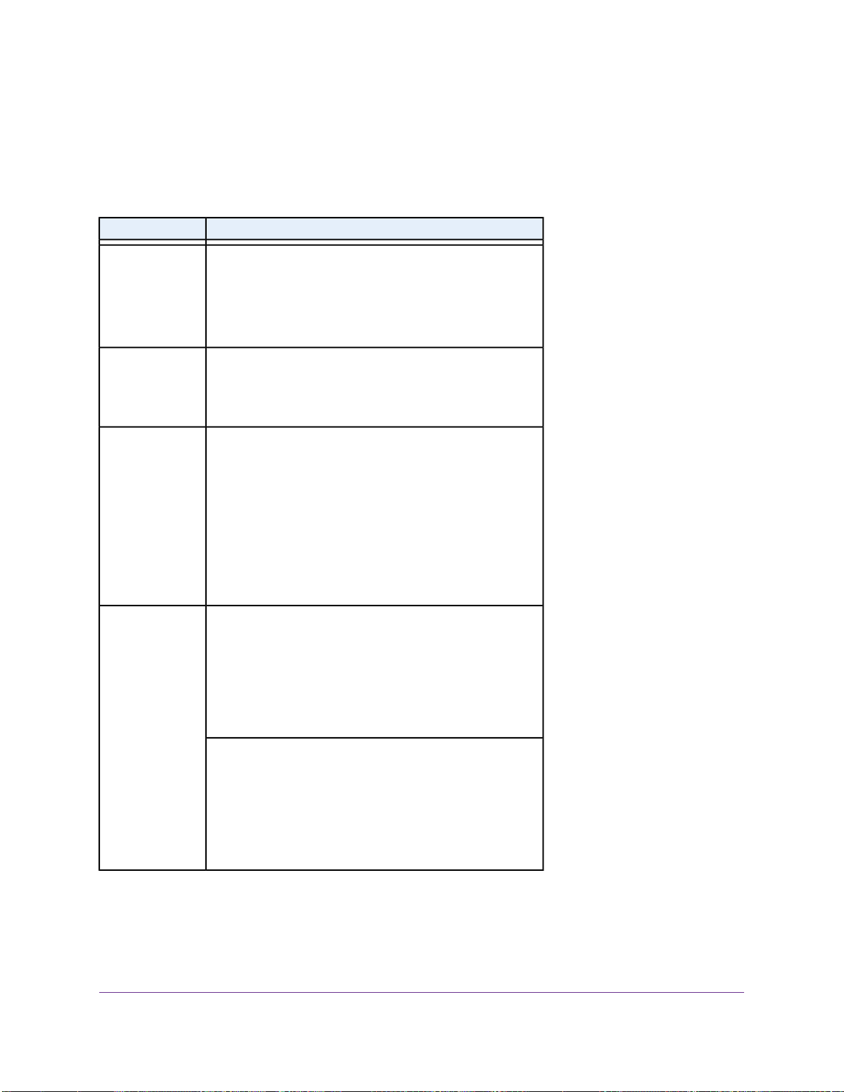
Table 3. LEDs on switch
DescriptionLED
• Solid green.The device is powered on.
• Solid yellow.The device is booting.
• Off. Power is not supplied to the device.
Power LED
• Solid yellow.The fans have failed.
• Off.The fan is operating normally.
Fan LED
• Off: No link is established.
• Solid green: A valid 1000 Mbps link is established.
• Blinking green.The port is transmitting or receiving
packets at 1000 Mbps.
• Solid yellow. A valid 10 or 100 Mbps link is established.
• Blinking yellow.The port is transmitting or receiving
packets at 10 or 100 Mbps.
Speed and ACT
LEDs for copper
ports 1 to 16
10G LED:
• Off: No SFP+ module link is established.
• Solid. A valid 10 Gbps link is established.
• Blinking.The SFP fiber port is transmitting or receiving
packets at 10 Gbps.
Speed and ACT
LEDs for SFP+
slots 15F and 16F
1G LED
• Off. No SFP+ module link is established.
• Solid. A valid 1 Gbps link is established.
• Blinking.The module is transmitting or receiving packets
at 1 Gbps.
Switch Hardware Interfaces
The following sections describe the hardware interfaces on the switch.
Hardware Overview
17
8-Port, 12-Port, and 16-Port Gigabit Smart Managed Pro Switch
Loading ...
Loading ...
Loading ...