HFC
utilized
R410A
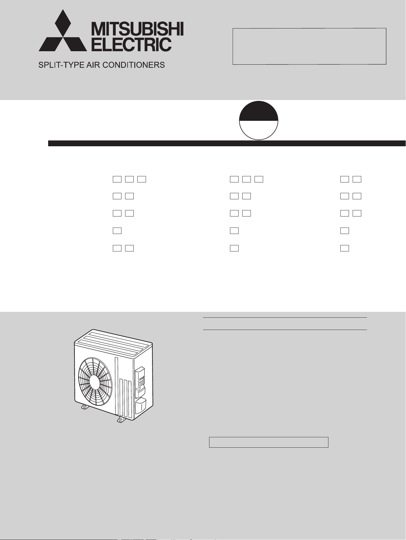
INDOOR UNIT
SERVICE MANUAL
No. OBH733
REVISED EDITION-J
Indoor unit service manual
MSZ-GL•NA, MSY-GL•NA Series (OBH732)
MUZ-GL18/24NA
MUZ-GL18/24NAH
MUY-GL18/24NA
PARTS CATALOG (OBB733)
OBH733 REVISED EDITION-H is void.
Revision J:
• A warning when opening or closing the valve has
been added.
CONTENTS
1. TECHNICAL CHANGES ······························3
2. PART NAMES AND FUNCTIONS ··················3
3. SPECIFICATION ········································4
4. OUTLINES AND DIMENSIONS ·····················7
5. WIRING DIAGRAM ·····································9
6. REFRIGERANT SYSTEM DIAGRAM ··········· 21
7. DATA······················································ 24
8. ACTUATOR CONTROL ····························· 39
9. SERVICE FUNCTIONS ······························ 40
10. TROUBLESHOOTING ······························· 41
11. DISASSEMBLY INSTRUCTIONS ················· 65
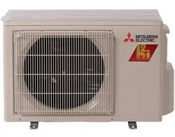
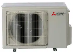
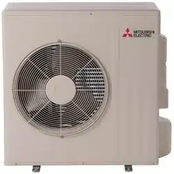
OUTDOOR UNIT
Models
MUZ-GL09NA
-
U1
,
U2
,
U8
MUZ-GL09NAH
-
U1
,
U2
,
U8
MUY-GL09NA
-
U1
,
U2
MUZ-GL12NA
-
U1
,
U2
MUZ-GL12NAH
-
U1
,
U2
MUY-GL12NA
-
U1
,
U2
MUZ-GL15NA
-
U1
,
U2
MUZ-GL15NAH
-
U1
,
U2
MUY-GL15NA
-
U1
,
U2
MUZ-GL18NA
-
U1
MUZ-GL18NAH
-
U1
MUY-GL18NA
-
U1
MUZ-GL24NA
-
U1
,
U2
MUZ-GL24NAH
-
U1
MUY-GL24NA
-
U1
2
Use the specied refrigerant only
Never use any refrigerant other than that specified.
Doing so may cause a burst, an explosion, or fire when the unit is being used, serviced, or disposed of.
Correct refrigerant is specified in the manuals and on the spec labels provided with our products.
We will not be held responsible for mechanical failure, system malfunction, unit breakdown or accidents caused by
failure to follow the instructions.
Revision A:
• MUZ-GL12/15NA-
U1
, MUZ-GL12/15NAH-
U1
and MUY-GL09/12/15NA-
U1
have been added.
Revision B:
• MUZ-GL09NA-
U8
and MUZ-GL09NAH-
U8
have been added.
Revision C:
• MUZ-GL09NA-
U1
and
MUZ-GL09NAH-
U1
have been added.
Revision D:
• MUZ-GL24NAH-
U1
has been added.
Revision E:
• Capacity corrections have been corrected [7-1. 2), 3)].
Revision F:
• MUZ-GL24NA-
U2
has been added
.
Revision G:
• MUZ-GL09/12/15NA-
U2
,
MUZ-GL09/12/15NAH-
U2
and MUY-GL09/12/15NA-
U2
have been added.
Revision H:
•
10-6. Voltage values of MUZ-GL09/12/15NA-
U2
,
MUZ-GL09/12/15NAH-
U2
and
MUY-GL09/12/15NA-
U2
have been corrected.
<Preparation before the repair service>
Prepare the proper tools.
Prepare the proper protectors.
Provide adequate ventilation.
After stopping the operation of the air conditioner, turn off the power-supply breaker and pull the power plug.
Discharge the capacitor before the work involving the electric parts.
<Precautions during the repair service>
Do not perform the work involving the electric parts with wet hands.
Do not pour water into the electric parts.
Do not touch the refrigerant.
Do not touch the hot or cold areas in the refrigeration cycle.
When the repair or the inspection of the circuit needs to be done without turning off the power, exercise great caution not to
touch the live parts.
WARNING
• When the refrigeration circuit has a leak, do not execute pump down with the
compressor.
• When pumping down the refrigerant, stop the compressor before disconnecting the
refrigerant pipes. The compressor may burst if air etc. get into it.
• When opening or closing the valve below freezing temperatures, refrigerant may
spurt out from the gap between the valve stem and the valve body, resulting in injuries.
Revision J:
• A warning when opening or closing the valve has been added.
OBH733J
3
1
TECHNICAL CHANGES
MUZ-GL18NA MUZ-GL18NAH MUY-GL18NA
MUZ-GL24NA MUZ-GL24NAH MUY-GL24NA
Piping
Air outlet
Drain outlet
Air inlet
(back and side)
Drain hose
PART NAMES AND FUNCTIONS
2
MUZ-GL09NA
-
U1
MUZ-GL09NAH
-
U1
MUY-GL09NA
-
U1
MUZ-GL09NA
-
U8
MUZ-GL09NAH
-
U8
MUZ-GL12NA
-
U1
MUZ-GL12NAH
-
U1
MUY-GL12NA
-
U1
MUZ-GL15NA
-
U1
MUZ-GL15NAH
-
U1
MUY-GL15NA
-
U1
MUZ-GL18NA
-
U1
MUZ-GL18NAH
-
U1
MUY-GL18NA
-
U1
MUZ-GL24NA
-
U1
,
U2
MUZ-GL24NAH
-
U1
MUY-GL24NA
-
U1
1. New model
MUZ-GL09NA MUZ-GL09NAH MUY-GL09NA
MUZ-GL12NA MUZ-GL12NAH MUY-GL12NA
MUZ-GL15NA MUZ-GL15NAH MUY-GL15NA
Air outlet
Drain outlet
Piping
Drain hose
Air inlet
(back and side)
MUZ-GL09NA
-
U1
MUZ-GL09NA
-
U2
MUZ-GL09NAH
-
U1
MUZ-GL09NAH
-
U2
1. Fan motor has been changed.
2. INVERTER P.C.BOARD has been changed.
3. EXPANSION VALVE has been changed.
4. 4-WAY VALVE has been changed.
5. R.V. COIL has been changed.
6. Compressor has been changed.
MUZ-GL12NA
-
U1
MUZ-GL12NA
-
U2
MUZ-GL12NAH
-
U1
MUZ-GL12NAH
-
U2
1. Fan motor has been changed.
2. INVERTER P.C.BOARD has been changed.
3. EXPANSION VALVE has been changed.
4. 4-WAY VALVE has been changed.
5. R.V. COIL has been changed.
MUY-GL09NA
-
U1
MUY-GL09NA
-
U2
1. Fan motor has been changed.
2. INVERTER P.C.BOARD has been changed.
3. EXPANSION VALVE has been changed.
4. 4-WAY VALVE has been changed.
5. Compressor has been changed.
6. Refrigerant charge has been changed.
MUY-GL12NA
-
U1
MUY-GL12NA
-
U2
1. Fan motor has been changed.
2. INVERTER P.C.BOARD has been changed.
3. EXPANSION VALVE has been changed.
4. 4-WAY VALVE has been changed.
MUZ-GL15NA
-
U1
MUZ-GL15NA
-
U2
MUZ-GL15NAH
-
U1
MUZ-GL15NAH
-
U2
MUY-GL15NA
-
U1
MUY-GL15NA
-
U2
1. Fan motor has been changed.
2. INVERTER P.C.BOARD has been changed.
3. EXPANSION VALVE has been changed.
OBH733J
4
3
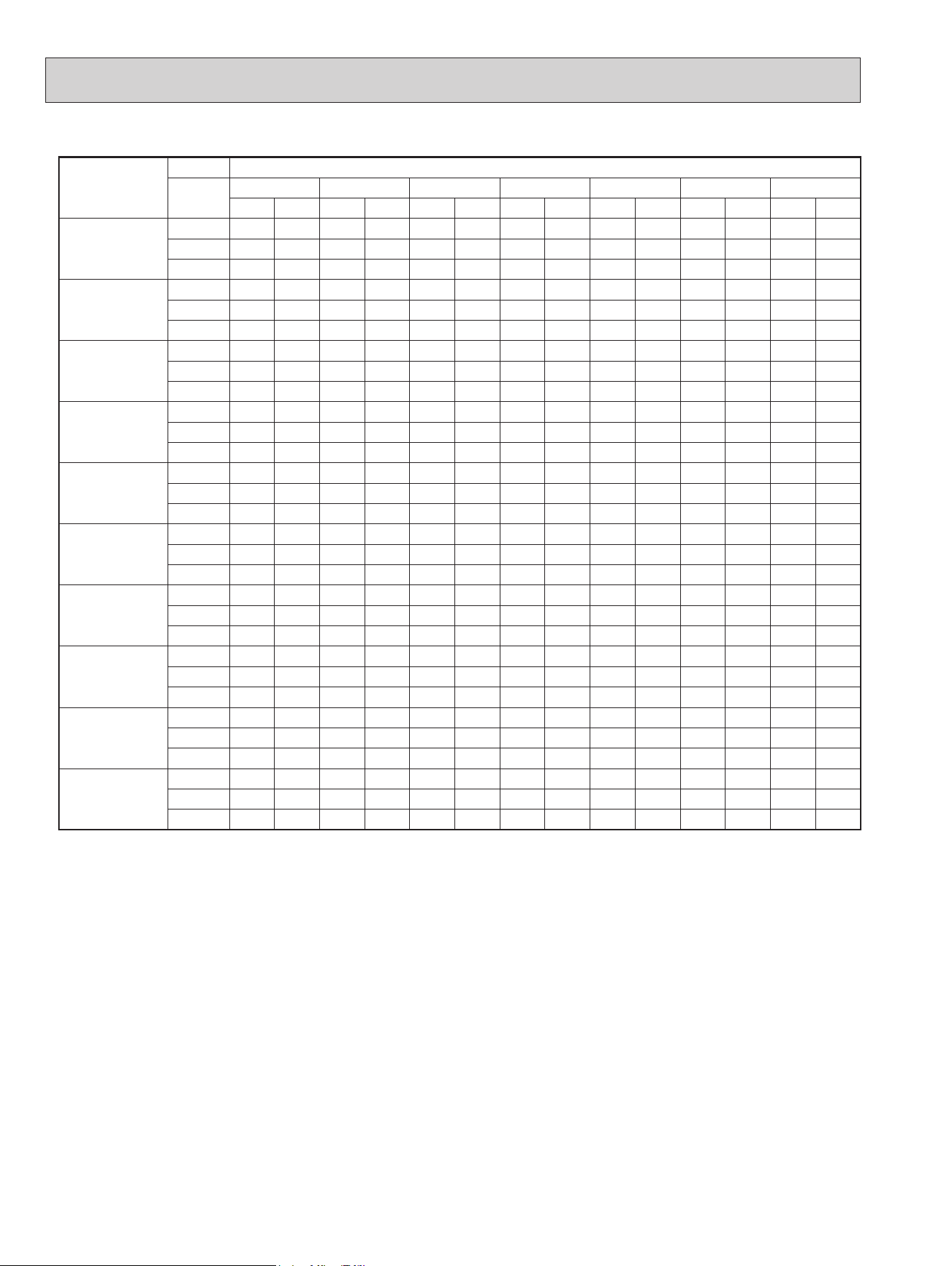
SPECIFICATION
Outdoor unit model
MUZ- MUY- MUZ- MUY-
GL09NA-
U1
GL09NAH-
U1
GL09NA-
U2
GL09NAH-
U2
GL09NA-
U8
GL09NAH-
U8
GL09NA
-
U1
GL09NA
-
U2
GL12NA
GL12NAH
GL12NA
Capacity
Rated (Minimum~Maximum)
Cooling *1
Btu/h 9,000 (3,600 - 12,200)
12,000 (1,500 - 13,600)
Heating 47 *1 (MUZ)
Btu/h
10,900
(4,500 - 15,900)
10,900
(4,500 - 14,100)
-
14,400
(2,000 - 18,100)
-
Capacity
Rated (Maximum)
Heating 17 *2 (MUZ)
Btu/h
6,700
(10,200)
7,000
(9,400)
-
9,200
(12,000)
-
Power consumption
Rated (Minimum~Maximum)
Cooling *1
W 585 (240 - 1,050) 920 (100 - 1,300)
Heating 47 *1 (MUZ)
W
720
(230 - 1,250)
720
(230 - 1,070)
-
1,100
(110 - 1,620)
-
Power consumption
Rated (Maximum)
Heating 17 *2 (MUZ)
W
630
(1,060)
620
(790)
-
870
(1,240)
-
EER
*1
[SEER]
*3
Cooling 15.4 [24.6] 13.0 [23.1]
HSPF IV
*4
Heating
(MUZ)
NA: 12.8
-
NA: 12.5
-
NAH: 11.8
-
NAH: 11.5
-
COP Heating
*
1
(MUZ)
4.44
-
3.84
-
Power factor
Cooling (208/230)
% 86/86 92/92 87/87 86/86 95/95
Heating
(MUZ) (208/230)
% 90/90 95/95
-
96/96
Power supply V , phase , Hz 208/230, 1 , 60
Max. fuse size (time delay) A 15
Min. circuit ampacity A 9 7 9 7
Fan motor F.L.A A 0.50
Compressor
Model
KNB073FRVMC KNB073FRXMC SNB092FQAMT KNB073FRVMC KNB073FRXMC
SNB092FQAMT
R.L.A A 6.2 4.9 6.6 4.9
L.R.A A 7.7 6.1 8.2 6.1
Refrigeration oil
oz. (L) (Model)
9.1 (0.27)/(FV50S)
11.8 (0.35)/(FV50S)
9.1 (0.27)/(FV50S)
11.8 (0.35)/(FV50S)
Refrigerant control Linear expansion valve
Sound level
*
1
Cooling dB(A) 48 49 49
Heating
(MUZ)
dB(A) 50
-
51
-
Airow
High - Med. - Low
Cooling CFM 1,102 - 639
Heating
(MUZ)
CFM
1,186 - 1,116 - 1,045
-
1,186 - 1,116 - 1,045
-
Fan speed
High - Med. - Low
Cooling rpm 810 - 490
Heating (MUZ) rpm
870 - 820 - 770
-
870 - 820 - 770
-
Defrost method Reverse cycle
-
Reverse cycle
-
Dimensions
W in. 31-1/2
D in. 11-1/4
H in. 21-5/8
Weight Ib. 81
External nish Munsell 3Y 7.8/1.1
Remote controller Wireless type
Control voltage
(by built-in transformer)
V DC 12 - 24
Refrigerant piping Not supplied
Refrigerant pipe size
(Min. wall thickness)
Liquid in. 1/4 (0.0315)
Gas in. 3/8 (0.0315)
Connection method
Indoor Flared
Outdoor Flared
Between the indoor
& outdoor units
Height dierence ft. 40
Piping length ft. 65
Refrigerant charge (R410A) 2 lb. 5 oz. 2 lb. 9 oz. 2 lb. 9 oz. 2 lb. 5 oz. 2 lb. 9 oz.
NOTE: Test conditions are based on AHRI 210/240.
*1: Rating conditions (Cooling) — Indoor: 80˚FDB, 67˚FWB, Outdoor: 95˚FDB, (75˚FWB)
(Heating) — Indoor: 70˚FDB, 60˚FWB, Outdoor: 47˚FDB, 43˚FWB
*2: Rating conditions (Heating) — Indoor: 70˚FDB, 60˚FWB, Outdoor: 17˚FDB, 15˚FWB
*3: Test condition (Refer to page 6.)
*4: Test condition (Refer to page 6.)
OBH733J
5
Outdoor unit model
MUZ- MUY-
MUZ- MUY- MUZ- MUY-
GL15NA
GL15NAH
GL15NA
GL18NA
GL18NAH
GL18NA
GL24NA
GL24NAH
GL24NA
Capacity
Rated (Minimum~Maximum)
Cooling *1
Btu/h
14,000 (3,100 - 18,200)
18,000 (5,800 ~ 22,000) 22,500 (8,200 ~ 31,400)
Heating 47 *1 (MUZ)
Btu/h
18,000
(4,800 - 20,900)
-
21,600
(5,400 ~ 25,000)
-
27,600
(7,500 ~ 36,900)
-
Capacity
Rated (Maximum)
Heating 17 *2 (MUZ)
Btu/h
12,200
(16,400)
- 13,800 (18,200) - 16,000 (24,600)
-
Power consumption
Rated (Minimum~Maximum)
Cooling *1
W 1,080 (210 - 2,000) 1,340 (330 ~ 2,150) 1,800 (570 ~ 3,580)
Heating 47 *1 (MUZ)
W
1,600
(200 ~ 2,010)
-
1,680 (320 ~ 2,500) 2,340 (520 ~ 3,650)
Power consumption
Rated (Maximum)
Heating 17 *2 (MUZ)
W
1,190
(1,850)
-
1,480
(2,150)
-
1,770
(3,290)
-
EER
*1
[SEER]
*3
Cooling 13.0 [21.6] 13.4 [20.5] 12.5 [20.5]
HSPF IV
*4
Heating
(MUZ)
NA: 11.7
-
NA: 11.2
-
NA: 10.0
-
NAH: 10.8
-
NAH: 10.2
-
NAH: 10.0
-
COP Heating
*
1
(MUZ)
3.30
-
3.77
-
3.46
-
Power factor
Cooling (208/230)
% 97/97 99/99 99/99
Heating
(MUZ) (208/230)
% 98/98 99/99
-
99/99
-
Power supply V , phase , Hz 208/230, 1 , 60
Max. fuse size (time delay) A 15 20
Min. circuit ampacity A 10 9 14 17.1
Fan motor F.L.A 0.50 0.93 0.93
Compressor
Model SNB130FQBMT SNB130FQBMT SNB172FQKMT
R.L.A A 7.4 6.8 10 12.9
L.R.A A 9.3 8.5 12.5 16.1
Refrigeration oil
oz. (L) (Model)
11.8 (0.35)/(FV50S)
11.8 (0.35)/(FV50S) 11.8 (0.35)/(FV50S) 13.5 (0.40)/(FV50S)
Refrigerant control Linear expansion valve
Sound level
*
1
Cooling dB(A) 49 49 54 55
Heating
(MUZ)
dB(A) 51
-
55
-
55
-
Airow
High - Med. - Low
COOL CFM 1,102-639 1,742 - 922 2,016 - 1,769 - 890
HEAT CFM
1,186 - 1,045 - 1,045
-
1,691 - 1,691 - 1,372
-
1,701 - 1,701 - 1,341
-
Fan speed
High - Med. - Low
Cooling rpm 810 - 490 840 - 450 950 - 840 - 450
Heating (MUZ) rpm
870 - 770 - 770
-
810 - 810 - 650
-
810 - 810 - 650
-
Defrost method
Reverse cycle
-
Reverse cycle
-
Reverse cycle
-
Dimensions
W in. 31-1/2 33-1/16
D in. 11-1/4 13
H in. 21-5/8 34-5/8
Weight Ib. 81 121 119
External nish Munsell 3Y 7.8/1.1
Remote controller Wireless type
Control voltage
(by built-in transformer)
V DC 12 - 24
Refrigerant piping Not supplied
Refrigerant pipe size
(Min. wall thickness)
Liquid in. 1/4 (0.0315) 3/8 (0.0315)
Gas in. 1/2 (0.0315) 5/8 (0.0315)
Connection method
Indoor Flared
Outdoor Flared
Between the indoor
& outdoor units
Height dierence ft. 40 50
Piping length ft. 65 100
Refrigerant charge (R410A) 2 lb. 9 oz. 3 lb. 9 oz. 4 lb. 3 oz.
NOTE: Test conditions are based on AHRI 210/240.
*1: Rating conditions (Cooling) — Indoor: 80˚FDB, 67˚FWB, Outdoor: 95˚FDB, (75˚FWB)
(Heating) — Indoor: 70˚FDB, 60˚FWB, Outdoor: 47˚FDB, 43˚FWB
*2: Rating conditions (Heating) — Indoor: 70˚FDB, 60˚FWB, Outdoor: 17˚FDB, 15˚FWB
*3: Test condition (Refer to page 6.)
*4: Test condition (Refer to page 6.)
OBH733J
6
Test condition
ARI
Mode Test
Indoor air condition (°F) Outdoor air condition (°F)
Dry bulb Wet bulb Dry bulb Wet bulb
SEER
(Cooling)
"A-2" Cooling Steady State
at rated compressor Speed
80 67 95 (75)
"B-2" Cooling Steady State
at rated compressor Speed
80 67 82 (65)
"B-1" Cooling Steady State
at minimum compressor Speed
80 67 82 (65)
"F-1" Cooling Steady State
at minimum compressor Speed
80 67 67 (53.5)
"E-V" Cooling Steady State
at intermediate compressor Speed *5
80 67 87 (69)
HSPF
(Heating)
"H1-2" Heating Steady State
at rated compressor Speed
70 60 47 43
"H3-2" Heating
at rated compressor Speed
70 60 17 15
"H0-1" Heating Steady State
at minimum compressor Speed
70 60 62 56.5
"H1-1" Heating Steady State
at minimum compressor Speed
70 60 47 43
"H2-V" Heating
at intermediate compressor Speed *5
70 60 35 33
NOTE:
*5
: At intermediate compressor Speed
= ("Rated compressor speed" - "minimum compressor speed") / 3 + "minimum compressor speed".
*
3, *4
(2) OPERATION
Mode Condition
Intake air temperature (°F)
Indoor Outdoor
DB WB DB WB
Cooling
Standard temperature 80 67 95 —
Maximum temperature 90 73 115 —
Minimum temperature 67 57 14 —
Maximum humidity 78 % —
Heating
Standard temperature 70 60 47 43
Maximum temperature 80 67 75 65
Minimum temperature 70 60 -4 -5
OPERATING RANGE
(1) POWER SUPPLY
Rated voltage Guaranteed voltage (V)
Outdoor unit
208/230 V
1 phase
60 Hz
Min. 187
208 230 Max. 253
OBH733J
7
OUTLINES AND DIMENSIONS
4
clear *1
*1
4 in. (100 mm) or more when
front and sides of the unit are clear
*2
When any 2 sides of left, right
and rear of the unit are clear
holes
(GL09/12/15NA)
(GL09/12/15NAH)
REQUIRED SPACE
Liquid refrigerant pipe joint
Refrigerant pipe (flared)
Ø 1/4
Gas refrigerant pipe joint
Refrigerant pipe (flared)
Ø 3/8 (GL09/12)
Ø 1/2 (GL15)
4 in. (100 mm)
or more
14 in. (350 mm)
or more
8 in. (200 mm)
or more *2
4 in. (100 mm)
or more
Unit: inch
MUZ-GL09NA MUZ-GL09NAH MUY-GL09NA
MUZ-GL12NA MUZ-GL12NAH MUY-GL12NA
MUZ-GL15NA MUZ-GL15NAH MUY-GL15NA
OBH733J
8
Unit: inch
16-7/16
1-9/16
1-5/8
Drain hole
6-7/8
19-11/16
13
2
Air in
Air in
Air out
2-holes 13/32 13/16
14-3/16
33-1/16
4-5/16
3-3/16
34-5/8
17-25/32
Service panel
3-29/32
6-1/2
7-11/16
35
44
Liquid refrigerant pipe joint
Refrigerant pipe (flared)
Ø 1/4 (GL18)
Refrigerant pipe (flared)
Ø 3/8 (GL24)
Gas refrigerant pipe joint
Refrigerant pipe (flared)
Ø 1/2 (GL18)
Refrigerant pipe (flared)
Ø 5/8 (GL24)
*1 20 in. (500 mm) or more when front
and sides of the unit are clear
14 in. (350 mm)
or more
4 in. (100 mm)
or more
REQUIRED SPACE
Clear *1
4 in. (100 mm)
or more
20 in. (500 mm)
or more *2
*2 When any 2 sides of left, right
and rear of the unit are clear
MUZ-GL18NA MUZ-GL18NAH MUY-GL18NA
MUZ-GL24NA MUZ-GL24NAH MUY-GL24NA
OBH733J
9
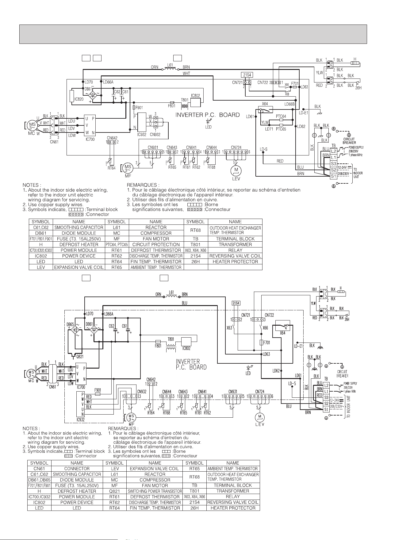
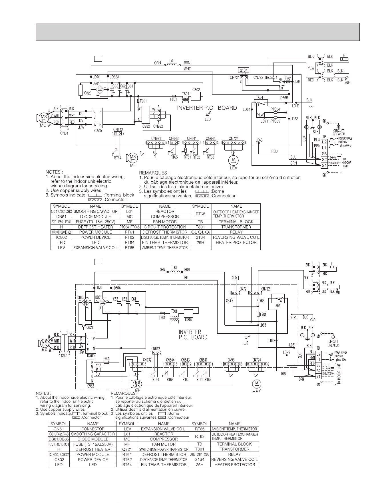
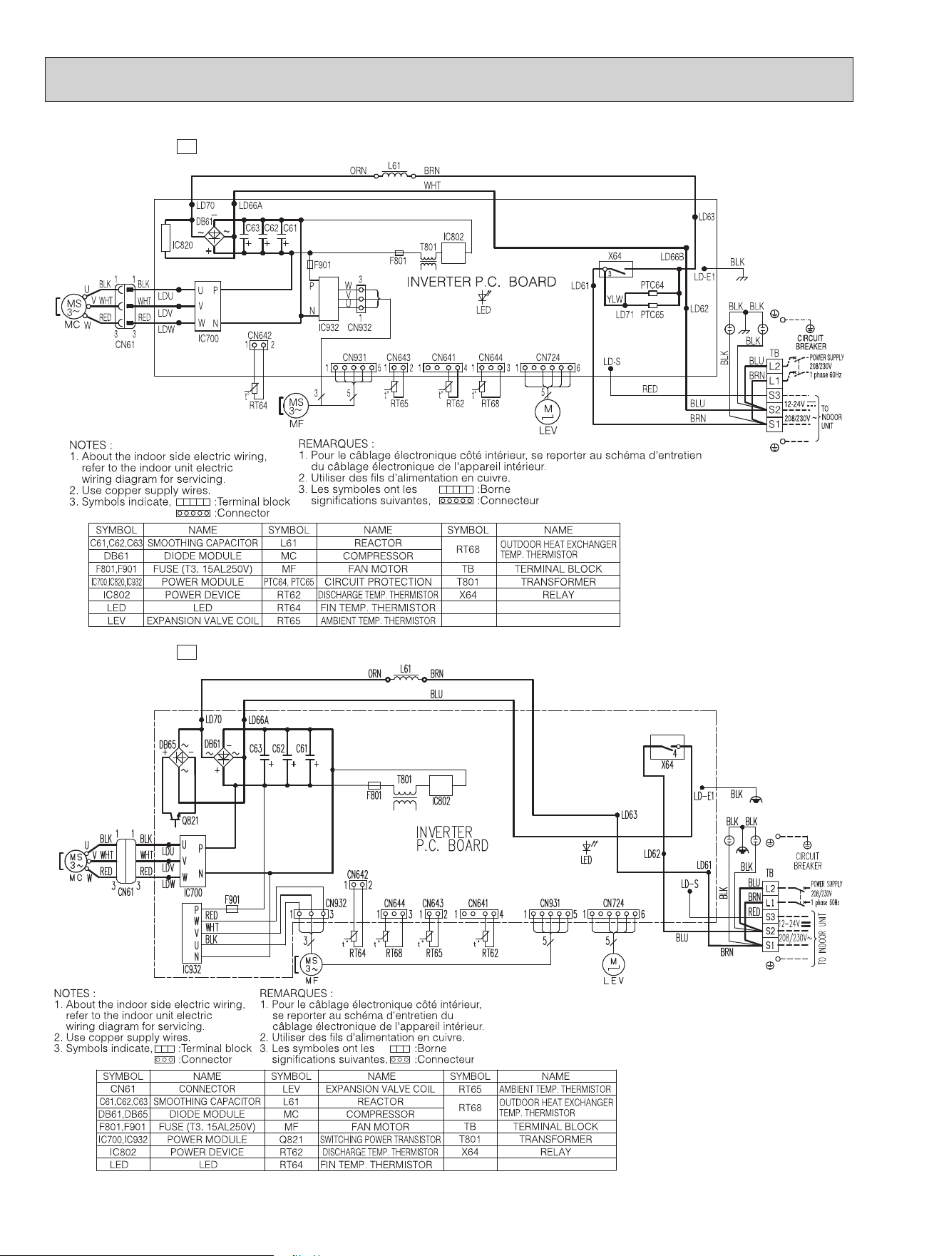
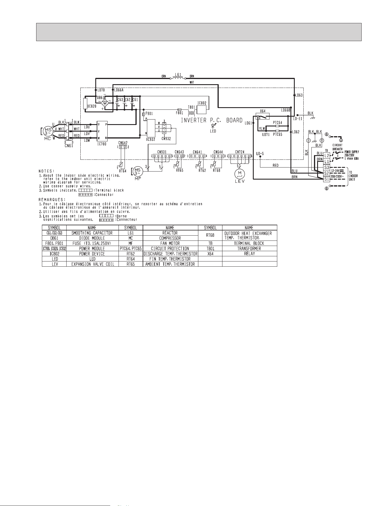
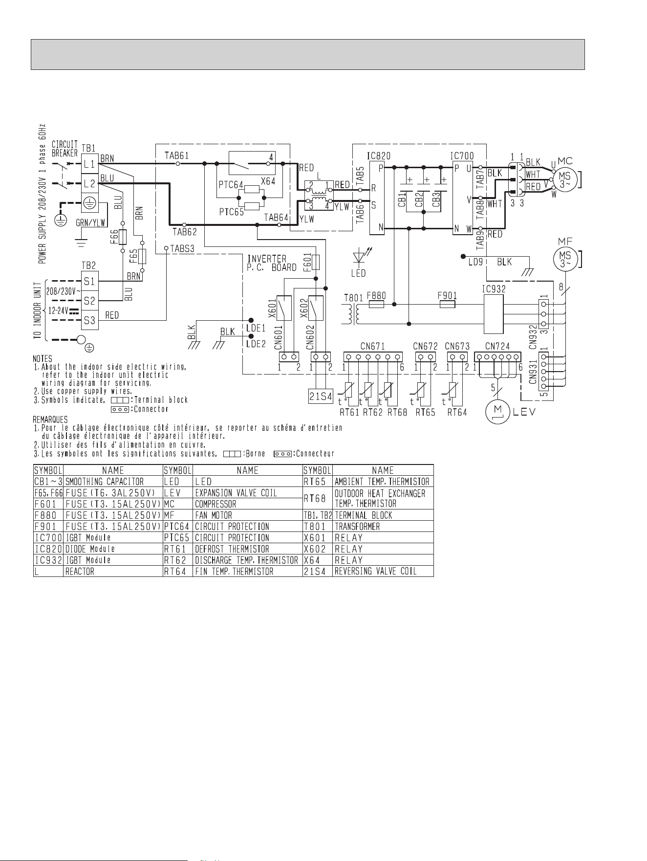
5
WIRING DIAGRAM
MUZ-GL09NA-
U1
,
U8
MUZ-GL12NA-
U1
MUZ-GL09NA-
U2
MUZ-GL12NA-
U2
OBH733J
10
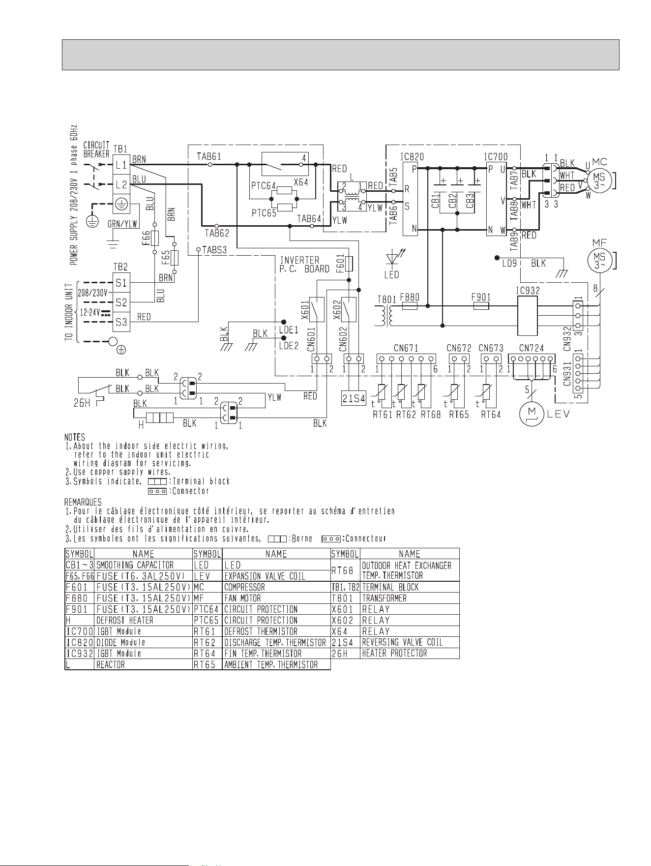
MUZ-GL09NAH-
U2
MUZ-GL12NAH-
U2
MUZ-GL09NAH-
U1
,
U8
MUZ-GL12NAH-
U1
OBH733J
11
MUY-GL09NA-
U1
MUY-GL12NA-
U1
MUY-GL09NA-
U2
MUY-GL12NA-
U2
OBH733J
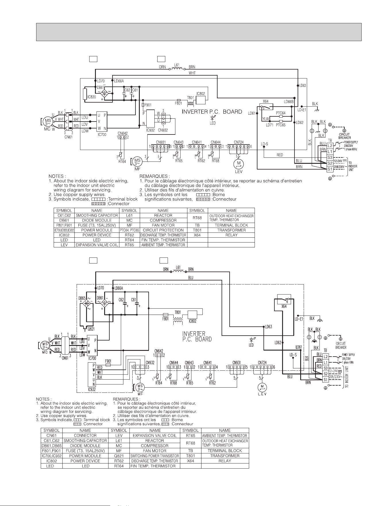
12
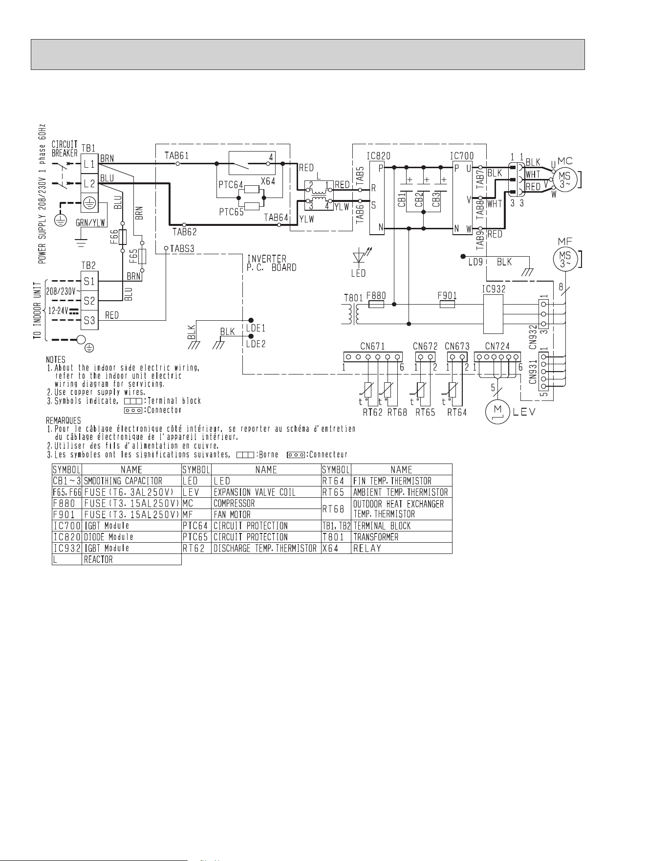
MUZ-GL15NA-
U2
MUZ-GL15NA-
U1
OBH733J
13
MUZ-GL15NAH-
U2
MUZ-GL15NAH-
U1
OBH733J
14
MUY-GL15NA-
U1
MUY-GL15NA-
U2
OBH733J
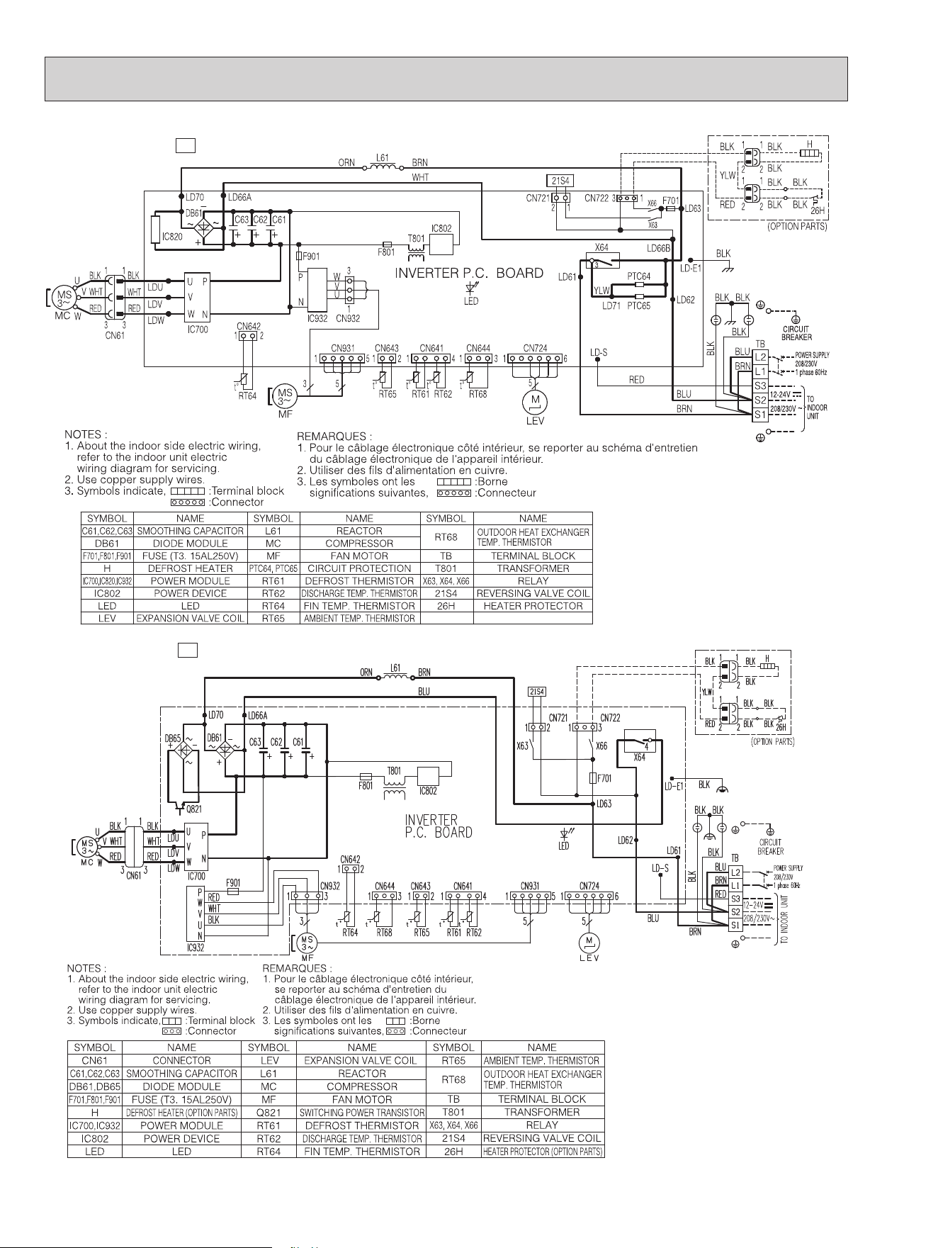
15
MUZ-GL18NA
OBH733J
16
MUZ-GL18NAH
OBH733J
17
MUY-GL18NA
OBH733J
18
MUZ-GL24NA
OBH733J
19
MUZ-GL24NAH
OBH733J
20
MUY-GL24NA
OBH733J
21
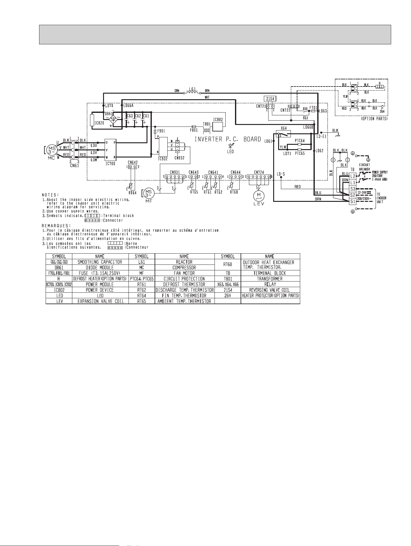
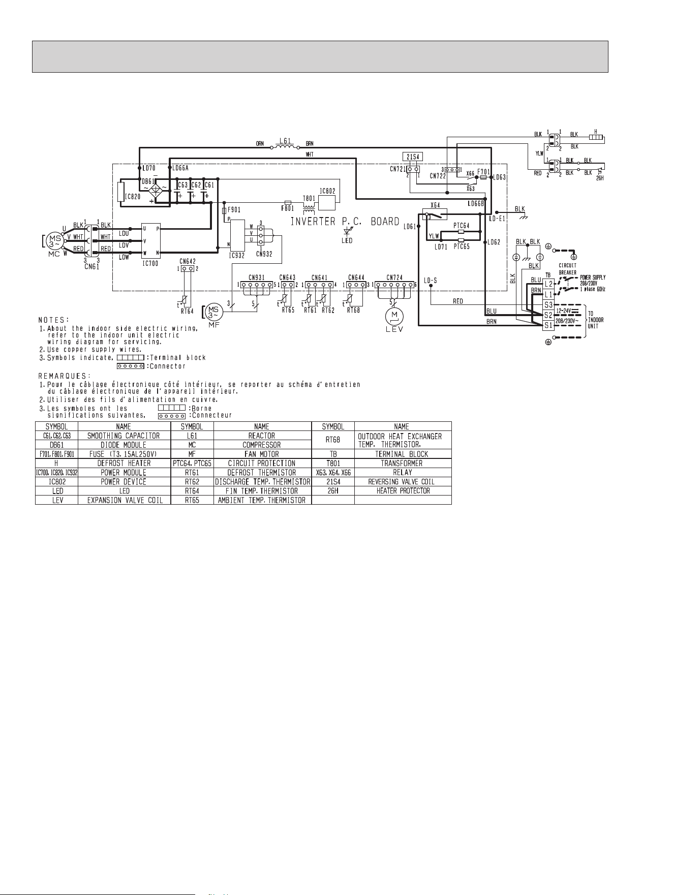
6
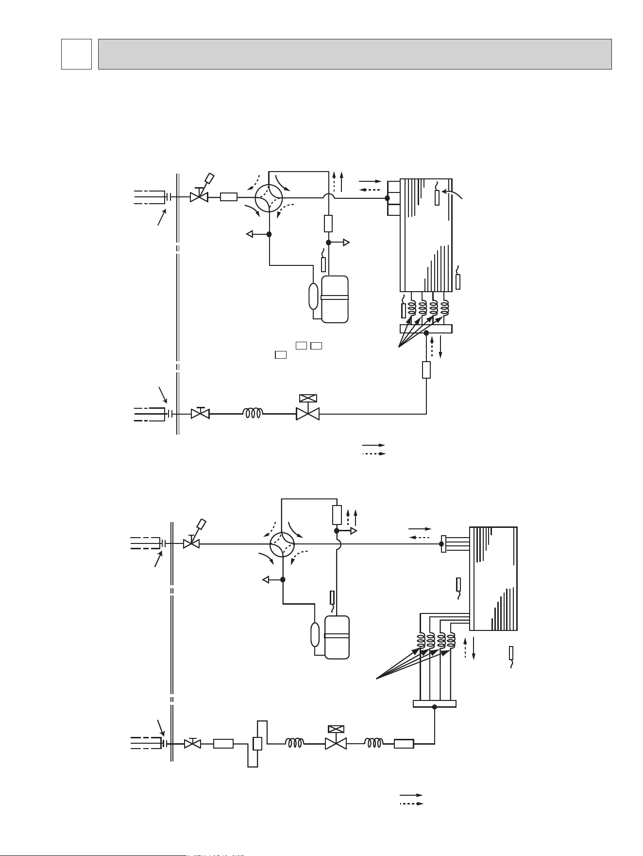
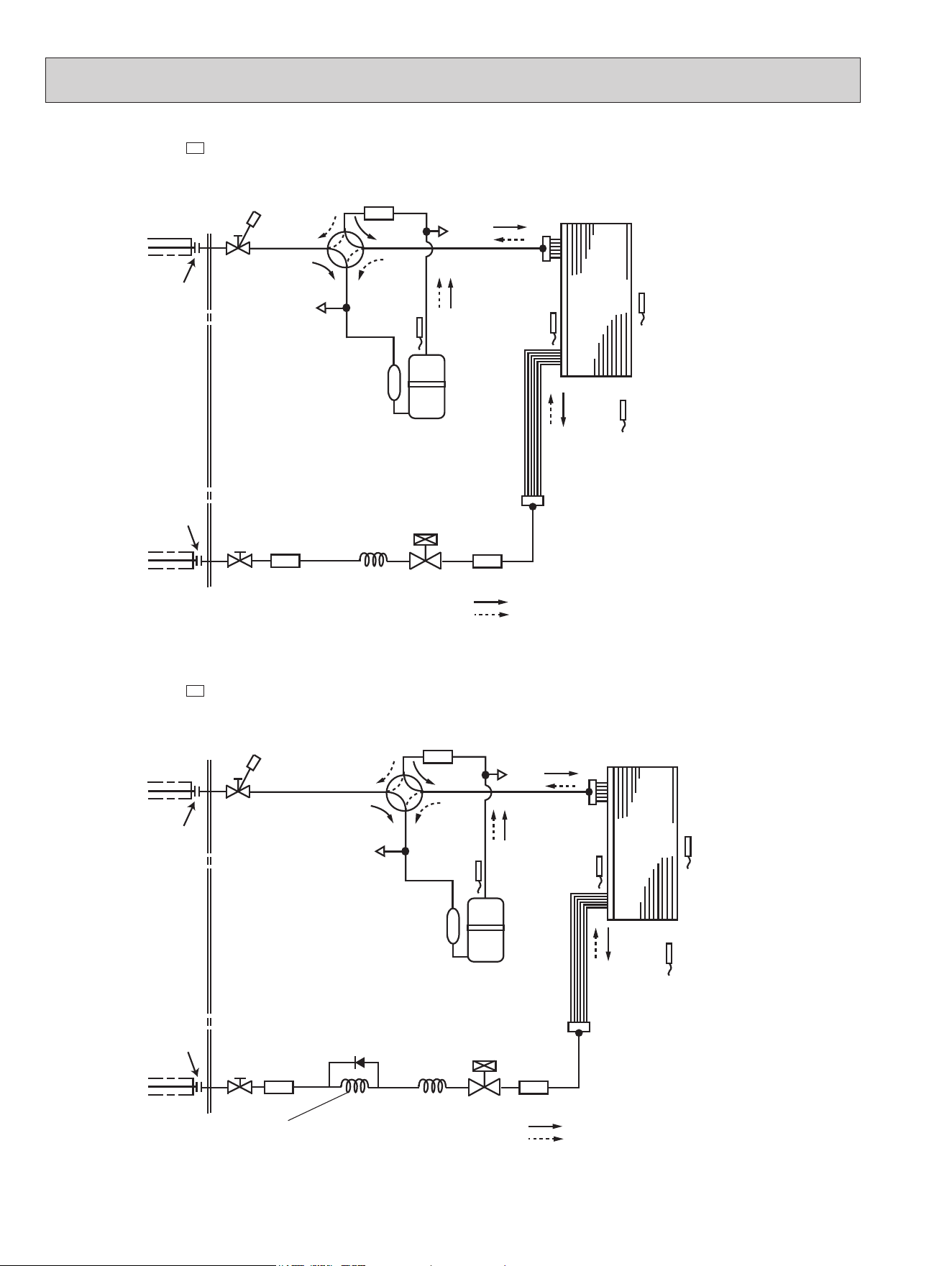
REFRIGERANT SYSTEM DIAGRAM
Unit: Inch (mm)
MUZ-GL18NA MUZ-GL18NAH MUY-GL18NA
Outdoor
heat
exchanger
Flared connection
Defrost
thermistor
RT61
(MUZ)
Discharge
temperature
thermistor
RT62
Flared connection
Stop valve
Capillary tube
O.D. 0.157×
I.D. 0.094×
3-15/16
(ø
4.0
×
ø
2.4
×
100)
Capillary tube
O.D. 0.157×
I.D. 0.094×7-7/8
(ø
4.0
×
ø
2.4
×
200)
Refrigerant flow in cooling
Compressor
4-way
valve
Refrigerant flow in heating (MUZ)
Refrigerant pipe
ø1/2
(
ø
12.7)
(with heat insulator)
Refrigerant pipe
ø1/4
(
ø
6.35)
(with heat insulator)
LEV
R.V. coil (MUZ)
heating ON
cooling OFF
Muffler
with #100 mesh strainer
Strainer
#100
Outdoor heat
exchanger
temperature
thermistor
RT68
Strainer
#100
Muffler
Capillary tube
O.D. 0.118×
I.D. 0.079× 7-7/8
(ø3.0×ø2.0×200(×4))
Stop valve
(with service port)
Service
port
Service port
Outdoor
heat
exchanger
Flared connection
Defrost
thermistor
RT61
(MUZ)
Discharge
temperature
thermistor
RT62
Flared connection
Stop valve
(with strainer)
Refrigerant flow in cooling
Compressor
4-way valve
Refrigerant flow in heating
(MUZ)
Refrigerant pipe ø1/4 (ø6.35)
(with heat insulator)
R.V. coil
(MUZ)
heating ON
cooling OFF
Strainer
#100
LEV
Ambient
temperature
thermistor
RT65
Muffler
Capillary tube
O.D. 0.118 ×
I.D. 0.079 × 9-7/16
(
ø3.0 × ø2.0 × 240
)
(MUZ-GL09NA/NAH-
U1 , U2
MUY-GL09NA- U2 )
Outdoor heat
exchanger
temperature
thermistor
RT68
Capillary tube
O.D. 0.118 ×
I.D. 0.079 × 8-9/32
(ø3.0 × ø2.0 × 210)
Service
port
Service
port
Refrigerant pipe ø3/8 (ø9.52) (GL09/12)
(with heat insulator)
ø1/2 (ø12.7) (GL15)
Stop valve
(with service port)
Capillary tube
O.D. 0.157 ×
I.D. 0.094 × 9-7/16
(
ø4.0 × ø2.4 × 240
)
(Other models
)
Muffler
MUZ-GL09NA MUZ-GL09NAH MUY-GL09NA
MUZ-GL12NA MUZ-GL12NAH MUY-GL12NA
MUZ-GL15NA MUZ-GL15NAH MUY-GL15NA
OBH733J
22
Outdoor
heat
exchanger
Flared connection
Defrost
thermistor
RT61
(MUZ)
Discharge
temperature
thermistor
RT62
Flared connection
Stop valve
Stop valve
(with service port)
Capillary tube
O.D.0.157
×
I.D.0.094
×
3-15/16
(ø
4.0
×
ø
2.4
×
100)
Refrigerant flow in cooling
Compressor
4-way valve
Refrigerant flow in heating (MUZ)
Refrigerant pipe
ø
5/8 (
ø15.88)
(with heat insulator)
Refrigerant pipe
ø
3/8 (
ø9.52)
(with heat insulator)
LEV
R.V. coil (MUZ)
heating ON
cooling OFF
Muffler
with #100 mesh strainer
Strainer
#100
Outdoor heat
exchanger
temperature
thermistor
RT68
Ambient
temperature
thermistor
RT65
Strainer
#100
Service
port
Service port
MUZ-GL24NA
-
U1
MUY-GL24NA
MUZ-GL24NA -
U2
MUZ-GL24NAH
Outdoor
heat
exchanger
Flared connection
Defrost
thermistor
RT61
Discharge
temperature
thermistor
RT62
Flared connection
Stop valve
Stop valve
(with service port)
Capillary tube
O.D.0.157
×
I.D.0.094
×
3-15/16
(ø
4.0
×
ø
2.4
×
100)
Capillary tube
O.D.0.118
×
I.D.0.071
×
21-21/32
(ø
3.0
×
ø
1.8
×
550)
Refrigerant flow in cooling
Compressor
4-way valve
Refrigerant flow in heating
Refrigerant pipe
ø
5/8 (
ø15.88)
(with heat insulator)
Refrigerant pipe
ø
3/8
(
ø9.52)
(with heat insulator)
LEV
R.V. coil
heating ON
cooling OFF
Muffler
#100
Strainer
#100
CHECK
VALVE
Outdoor heat
exchanger
temperature
thermistor
RT68
Ambient
temperature
thermistor
RT65
Strainer
#100
Service
port
Service
port
Unit: inch
OBH733J
23
Max. Length
A
Max. Height
difference
B
Indoor
unit
Outdoor unit
MAX. REFRIGERANT PIPING LENGTH and MAX. HEIGHT DIFFERENCE
Model
Refrigerant piping: ft. Piping size O.D: in.
Max. Length
A
Max. Height dierence
B
Gas Liquid
MUZ-GL09NA
MUZ-GL09NAH
MUY-GL09NA
MUZ-GL12NA
MUZ-GL12NAH
MUY-GL12NA
65 40 3/8 1/4
MUZ-GL15NA
MUZ-GL15NAH
MUY-GL15NA
65 40 1/2 1/4
MUZ-GL18NA
MUZ-GL18NAH
MUY-GL18NA
100 50 1/2 1/4
MUZ-GL24NA
MUZ-GL24NAH
MUY-GL24NA
100 50 5/8 3/8
ADDITIONAL REFRIGERANT CHARGE (R410A: oz.)
NOTE: Refrigerant piping exceeding 25 ft. requires additional refrigerant charge according to the calculation.
Model
Outdoor unit
precharged
Refrigerant piping length (one way): ft.
25 30 40 50 60 65
MUZ-GL09NA
-
U1
MUZ-GL09NA
-
U2
MUZ-GL09NAH
-
U1
MUZ-GL09NAH
-
U2
MUY-GL09NA
-
U2
2 lb. 5 oz.
0 1.08 3.24 5.40 7.56 8.64
MUZ-GL09NA
-
U8
MUZ-GL09NAH
-
U8
MUY-GL09NA
-
U1
MUZ-GL12NA
MUZ-GL12NAH
MUY-GL12NA
MUZ-GL15NA
MUZ-GL15NAH
MUY-GL15NA
2 lb. 9 oz.
Calculation: X oz. = 1.08/5 oz./ft. × (Refrigerant piping length (ft.) - 25)
OBH733J
24
NOTE: Refrigerant piping exceeding 25 ft. requires additional refrigerant charge according to the calculation.
Model
Outdoor unit
precharged
Refrigerant piping length (one way): ft.
25 30 40 50 60 70 80 90 100
MUZ-GL18NA
MUZ-GL18NAH
MUY-GL18NA
3 lb. 9 oz. 0 1.08 3.24 5.40 7.56 9.72 11.88 14.04 16.20
Calculation: X oz. = 1.08/5 oz./ft. × (Refrigerant piping length (ft.) - 25)
NOTE: Refrigerant piping exceeding 33 ft. requires additional refrigerant charge according to the calculation.
Model
Outdoor unit
precharged
Refrigerant piping length (one way): ft.
33 40 50 60 70 80 90 100
MUZ-GL24NA
MUZ-GL24NAH
MUY-GL24NA
4 lb. 3 oz. 0 4.14 10.06 15.98 21.90 27.82 33.74 39.66
Calculation: X oz. = 2.96/5 oz./ft. × (Refrigerant piping length (ft.) - 33)
DATA7
7-1. PERFORMANCE DATA
1) COOLING CAPACITY
Model
Indoor air
Outdoor intake air DB temperature (˚F)
IWB (˚F)
75 85 95 105 115
TC SHC TPC TC SHC TPC TC SHC TPC TC SHC TPC TC SHC TPC
MUZ-GL09NA
MUZ-GL09NAH
MUY-GL09NA
71 11.0 7.6 0.52 10.3 7.1 0.57 9.7 6.6 0.61 9.0 6.2 0.65 8.3 5.7 0.67
67 10.4 8.6 0.49 9.7 8.0 0.54 9.0 7.4 0.59 8.4 6.9 0.62 7.7 6.3 0.65
63 9.8 9.4 0.47 9.1 8.7 0.52 8.5 8.1 0.56 7.7 7.3 0.60 7.0 6.7 0.62
MUZ-GL12NA
MUZ-GL12NAH
MUY-GL12NA
71 14.7 9.4 0.82 13.7 8.7 0.90 12.9 8.2 0.97 12.0 7.6 1.02 11.0 7.0 1.06
67 13.9 10.7 0.77 13.0 10.0 0.85 12.0 9.2 0.92 11.2 8.6 0.98 10.3 7.9 1.02
63 13.1 11.8 0.74 12.1 10.9 0.81 11.3 10.2 0.88 10.3 9.3 0.94 9.4 8.5 0.98
MUZ-GL15NA
MUZ-GL15NAH
MUY-GL15NA
71 17.2 9.7 0.96 16.0 9.1 1.05 15.1 8.5 1.13 14.0 7.9 1.19 12.9 7.3 1.24
67 16.2 11.4 0.91 15.1 10.6 1.00 14.0 9.8 1.08 13.0 9.1 1.14 12.0 8.4 1.20
63 15.3 12.7 0.86 14.1 11.8 0.96 13.2 11.0 1.03 12.0 10.0 1.10 10.9 9.1 1.14
MUZ-GL18NA
MUZ-GL18NAH
MUY-GL18NA
71 22.1 16.2 1.19 20.6 15.2 1.31 19.4 14.3 1.41 18.0 13.3 1.48 16.6 12.2 1.54
67 20.9 18.2 1.13 19.4 16.9 1.24 18.0 15.7 1.34 16.7 14.6 1.42 15.4 13.4 1.49
63 19.6 19.7 1.07 18.2 18.2 1.19 16.9 17.0 1.28 15.4 15.4 1.37 14.0 14.1 1.42
MUZ-GL24NA
MUZ-GL24NAH
MUY-GL24NA
71 27.6 17.0 1.60 25.8 15.9 1.76 24.2 14.9 1.89 22.5 13.9 1.99 20.7 12.8 2.07
67 26.1 19.6 1.51 24.3 18.2 1.67 22.5 16.9 1.80 20.9 15.7 1.91 19.2 14.4 2.00
63 24.5 21.7 1.44 22.7 20.1 1.59 21.2 18.7 1.72 19.2 17.0 1.84 17.6 15.5 1.91
NOTE: 1. IWB : Intake air wet-bulb temperature TC : Total Capacity (x10
3
Btu/h)
SHC : Sensible Heat Capacity (x10
3
Btu/h) TPC : Total Power Consumption (kW)
2. SHC is based on 80˚F of indoor Intake air DB temperature.
MUZ-GL09NA MUZ-GL09NAH MUY-GL09NA
MUZ-GL12NA MUZ-GL12NAH MUY-GL12NA
MUZ-GL15NA MUZ-GL15NAH MUY-GL15NA
MUZ-GL18NA MUZ-GL18NAH MUY-GL18NA
MUZ-GL24NA MUZ-GL24NAH MUY-GL24NA
OBH733J
25
2) COOLING CAPACITY CORRECTIONS
Model
Refrigerant piping length (one way: ft.)
25 (std.) 40 65 100
MUZ-GL09NA
MUZ-GL09NAH
MUY-GL09NA
MUZ-GL12NA
MUZ-GL12NAH
MUY-GL12NA
MUZ-GL15NA
MUZ-GL15NAH
MUY-GL15NA
1.0 0.988 0.967 -
MUZ-GL18NA
MUZ-GL18NAH
MUY-GL18NA
1.0 0.985 0.963 0.933
MUZ-GL24NA
MUZ-GL24NAH
MUY-GL24NA
1.0 0.983 0.956 0.921
3) HEATING CAPACITY CORRECTIONS
Model
Refrigerant piping length (one way: ft.)
25 (std.) 40 65 100
MUZ-GL09NA
MUZ-GL09NAH
MUZ-GL12NA
MUZ-GL12NAH
MUZ-GL15NA
MUZ-GL15NAH
1.0 0.997 0.993 -
MUZ-GL18NA
MUZ-GL18NAH
MUZ-GL24NA
MUZ-GL24NAH
1.0 0.997 0.993 0.987
OBH733J
26
4) HEATING CAPACITY (MUZ)
Model
Indoor air
Outdoor intake air WB temperature (˚F)
IDB (˚F)
5 15 25 35 43 45 55
TC TPC TC TPC TC TPC TC TPC TC TPC TC TPC TC TPC
MUZ-GL09NA
75 4.8 0.42 6.3 0.54 7.9 0.63 9.4 0.70 10.6 0.74 11.0 0.75 12.4 0.78
70 5.2 0.41 6.7 0.52 8.2 0.62 9.6 0.68 10.9 0.72 11.2 0.73 12.7 0.76
65 5.5 0.39 6.9 0.50 8.6 0.59 10.0 0.67 11.2 0.70 11.6 0.71 13.0 0.75
MUZ-GL09NAH
75 4.8 0.55 6.3 0.67 7.9 0.76 9.4 0.70 10.6 0.74 11.0 0.75 12.4 0.78
70 5.2 0.54 6.7 0.65 8.2 0.75 9.6 0.68 10.9 0.72 11.2 0.73 12.7 0.76
65 5.5 0.52 6.9 0.63 8.6 0.72 10.0 0.67 11.2 0.70 11.6 0.71 13.0 0.75
MUZ-GL12NA
75 6.3 0.65 8.4 0.82 10.4 0.96 12.5 1.07 14.0 1.13 14.5 1.14 16.4 1.19
70 6.8 0.62 8.9 0.79 10.8 0.94 12.7 1.05 14.4 1.10 14.8 1.12 16.8 1.17
65 7.2 0.59 9.1 0.76 11.3 0.91 13.2 1.02 14.8 1.07 15.3 1.09 17.1 1.14
MUZ-GL12NAH
75 6.3 0.78 8.4 0.95 10.4 1.09 12.5 1.07 14.0 1.13 14.5 1.14 16.4 1.19
70 6.8 0.75 8.9 0.92 10.8 1.07 12.7 1.05 14.4 1.10 14.8 1.12 16.8 1.17
65 7.2 0.72 9.1 0.89 11.3 1.04 13.2 1.02 14.8 1.07 15.3 1.09 17.1 1.14
MUZ-GL15NA
75 7.9 0.94 10.4 1.19 13.1 1.40 15.6 1.56 17.6 1.64 18.1 1.66 20.5 1.73
70 8.6 0.90 11.1 1.15 13.5 1.37 15.9 1.52 18.0 1.60 18.5 1.63 21.0 1.70
65 9.0 0.86 11.3 1.10 14.1 1.32 16.5 1.48 18.5 1.56 19.1 1.58 21.4 1.66
MUZ-GL15NAH
75 7.9 1.07 10.4 1.32 13.1 1.53 15.6 1.56 17.6 1.64 18.1 1.66 20.5 1.73
70 8.6 1.03 11.1 1.28 13.5 1.50 15.9 1.52 18.0 1.60 18.5 1.63 21.0 1.70
65 9.0 0.99 11.3 1.23 14.1 1.45 16.5 1.48 18.5 1.56 19.1 1.58 21.4 1.66
MUZ-GL18NA
75 9.5 0.99 12.5 1.25 15.7 1.47 18.7 1.64 21.1 1.72 21.7 1.75 24.6 1.81
70 10.3 0.95 13.3 1.21 16.2 1.44 19.1 1.60 21.6 1.68 22.2 1.71 25.2 1.78
65 10.8 0.91 13.6 1.16 17.0 1.39 19.8 1.55 22.2 1.64 22.9 1.66 25.7 1.75
MUZ-GL18NAH
75 9.5 1.12 12.5 1.38 15.7 1.60 18.7 1.64 21.1 1.72 21.7 1.75 24.6 1.81
70 10.3 1.08 13.3 1.34 16.2 1.57 19.1 1.60 21.6 1.68 22.2 1.71 25.2 1.78
65 10.8 1.04 13.6 1.29 17.0 1.52 19.8 1.55 22.2 1.64 22.9 1.66 25.7 1.75
MUZ-GL24NA
75 12.1 1.38 16.0 1.74 20.0 2.05 23.9 2.28 26.9 2.40 27.7 2.43 31.5 2.53
70 13.1 1.32 17.0 1.68 20.7 2.00 24.4 2.22 27.6 2.34 28.4 2.39 32.2 2.48
65 13.8 1.26 17.4 1.61 21.7 1.93 25.3 2.16 28.4 2.28 29.3 2.32 32.8 2.43
MUZ-GL24NAH
75 12.1 1.38 16.0 1.74 20.0 2.05 23.9 2.28 26.9 2.40 27.7 2.43 31.5 2.53
70 13.1 1.32 17.0 1.68 20.7 2.00 24.4 2.22 27.6 2.34 28.4 2.39 32.2 2.48
65 13.8 1.26 17.4 1.61 21.7 1.93 25.3 2.16 28.4 2.28 29.3 2.32 32.8 2.43
NOTE: 1. IDB : Intake air dry-bulb temperature
TC : Total Capacity (x10
3
Btu/h) TPC : Total Power Consumption (kW)
2. Above data is for heating operation without any frost.
How to operate with fixed operational frequency of the compressor.
1. Press the EMERGENCY OPERATION switch on the front of the indoor unit, and select either EMERGENCY COOL
mode or EMERGENCY HEAT mode before starting to operate the air conditioner.
2. The compressor starts with operational frequency.
3. The fan speed of the indoor unit is High.
4. This operation continues for 30 minutes.
5. In order to release this operation, press the EMERGENCY OPERATION switch or press any button on the remote con-
troller.
OBH733J
27
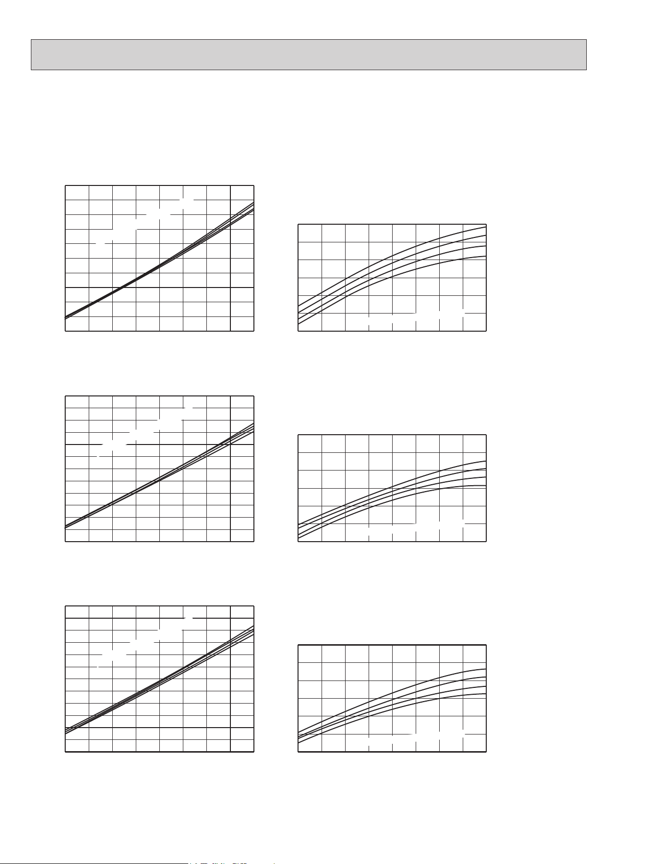
7-2. PERFORMANCE CURVE
Cooling
This value of frequency is not the same as the actual frequency in operating. Refer to 7-5 and 7-6 for the relationships
between frequency and capacity.
MUZ-GL18NA MUZ-GL18NAH MUY-GL18NA
Cooling capacity (
at Rated frequency)
0.9
1.0
1.1
1.2
1.3
1.4
1.5
14 23 32 41 50 59 68 77 86 95 104 113
Outdoor intake air DB temperature(°F)
Capacity correction factors
79
75
68
64
72
Indoor intake air Wet-bulb
temperature( F)
71
67
63
65 75 85 95 105 115
0.9
1.0
1.1
1.2
1.3
1.4
1.5
1.6
Indoor intake air WB temperature (°F)
SHF at rating condition = 0.87
= 646 CFM
Airflow
Outdoor intake air DB temperature (°F)
Total power consumption
(kW)
71
67
63
65 75 85 95 105 115
0.6
0.7
0.8
0.9
1.0
1.1
Indoor intake air WB temperature (°F)
SHF at rating condition = 0.77
= 399 CFM
Airflow
Outdoor intake air DB temperature (°F)
Total power consumption
(kW)
71
67
63
65 75 85 95 105 115
0.2
0.3
0.4
0.5
0.6
0.7
Indoor intake air WB temperature (°F)
SHF at rating condition = 0.82
= 399 CFM
Airflow
Outdoor intake air DB temperature (°F)
Total power consumption
(kW)
71
67
63
65 75 85 95 105 115
0.7
0.8
0.9
1.0
1.1
1.2
1.3
1.4
1.5
Indoor intake air WB temperature (°F)
SHF at rating condition = 0.78
= 533 CFM
Airflow
Outdoor intake air DB temperature (°F)
Total power consumption
(kW)
MUZ-GL24NA MUZ-GL24NAH MUY-GL24NA
71
67
63
65 75 85 95 105 115
1.3
1.4
1.5
1.6
1.7
1.8
1.9
2.0
2.1
2.2
Indoor intake air WB temperature (°F)
SHF at rating condition = 0.75
= 634 CFM
Airflow
Outdoor intake air DB temperature (°F)
Total power consumption
(kW)
MUZ-GL12NA MUZ-GL12NAH MUY-GL12NA
MUZ-GL09NA MUZ-GL09NAH MUY-GL09NA
MUZ-GL15NA MUZ-GL15NAH MUY-GL15NA
OBH733J
28
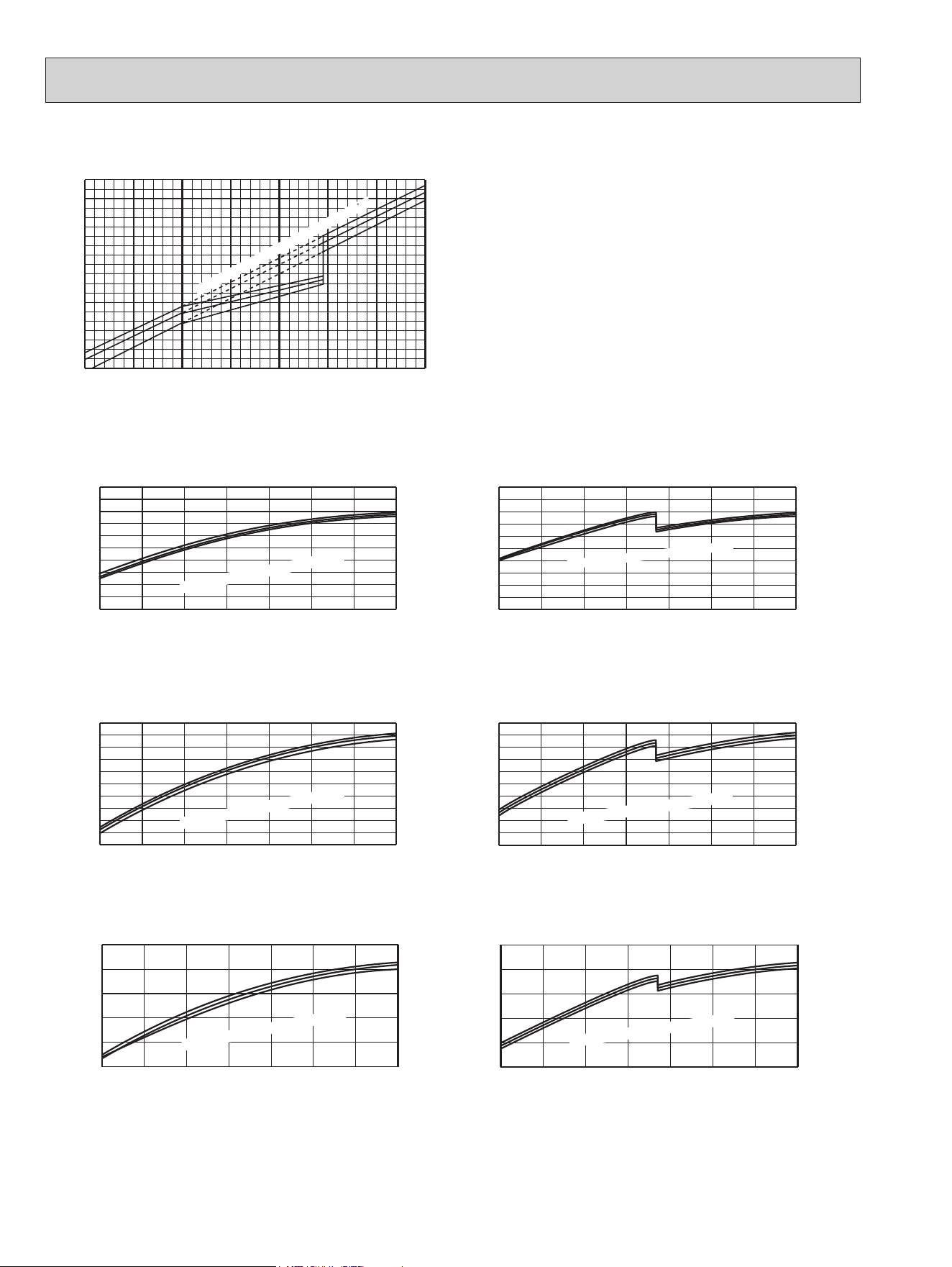
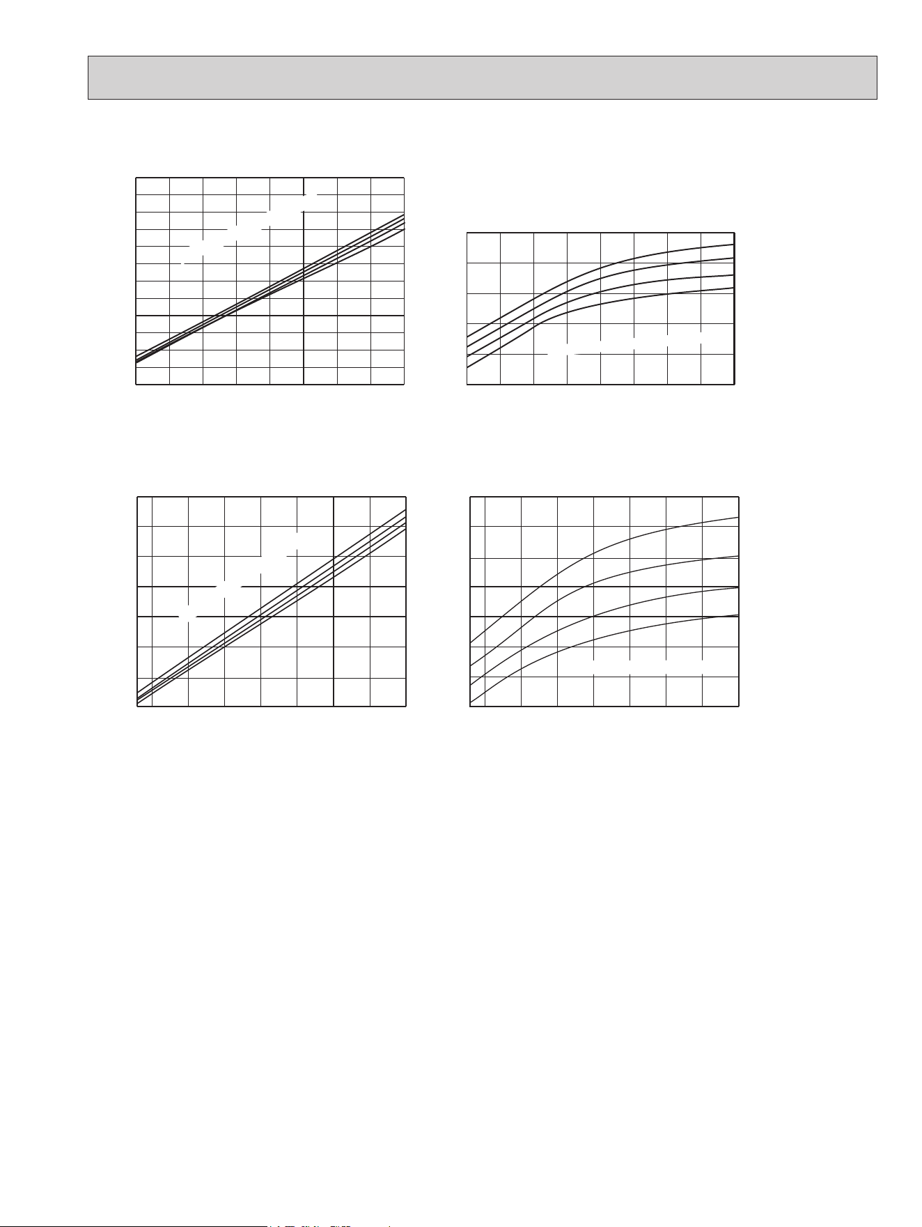
Heating
Outdoor intake air WB temperature (°F)
-4 5 14 23 32 41 50 59
0.4
0.5
0.6
0.7
0.8
0.9
1.0
1.1
1.2
1.3
Heating capacity (
at Rated frequency)
Capacity correction factor
59
68
79
Indoor intake air Dry-bulb temperature ( F)
MUZ-GL09NA
MUZ-GL12NA
MUZ-GL09NAH
MUZ-GL12NAH
MUZ-GL15NA MUZ-GL15NAH
75
70
65
-5 5 15 25 35 45 55
65
0.0
0.1
0.2
0.3
0.4
0.5
0.6
0.7
0.8
0.9
1.0
Indoor intake air DB temperature (°F)
= 406 CFM
Airflow
Outdoor intake air WB temperature (°F)
Total power consumption
(kW)
75
70
65
-5 5 15 25 35 45 55
65
0.3
0.4
0.5
0.6
0.7
0.8
0.9
1.0
1.1
1.2
1.3
Indoor intake air DB temperature (°F)
= 406 CFM
Airflow
Outdoor intake air WB temperature (°F)
Total power consumption
(kW)
75
70
65
-5 5 15 25 35 45 55
65
0.5
0.8
1.1
1.4
1.7
2.0
Indoor intake air DB temperature (°F)
= 463 CFM
Airflow
Outdoor intake air WB temperature (°F)
Total power consumption
(kW)
65
70
75
-5 5 15 25 35 45 55
65
0.0
0.1
0.2
0.3
0.4
0.5
0.6
0.7
0.8
0.9
1.0
Indoor intake air DB temperature (°F)
= 406 CFM
Airflow
Outdoor intake air WB temperature (°F)
Total power consumption
(kW)
65
70
75
-5 5 15 25 35 45 55
65
0.3
0.4
0.5
0.6
0.7
0.8
0.9
1.0
1.1
1.2
1.3
Indoor intake air DB temperature (°F)
= 406 CFM
Airflow
Outdoor intake air WB temperature (°F)
Total power consumption
(kW)
65
70
75
-5 5 15 25 35 45 55
65
0.5
0.8
1.1
1.4
1.7
2.0
Indoor intake air DB temperature (°F)
= 463 CFM
Airflow
Outdoor intake air WB temperature (°F)
Total power consumption
(kW)
OBH733J
29
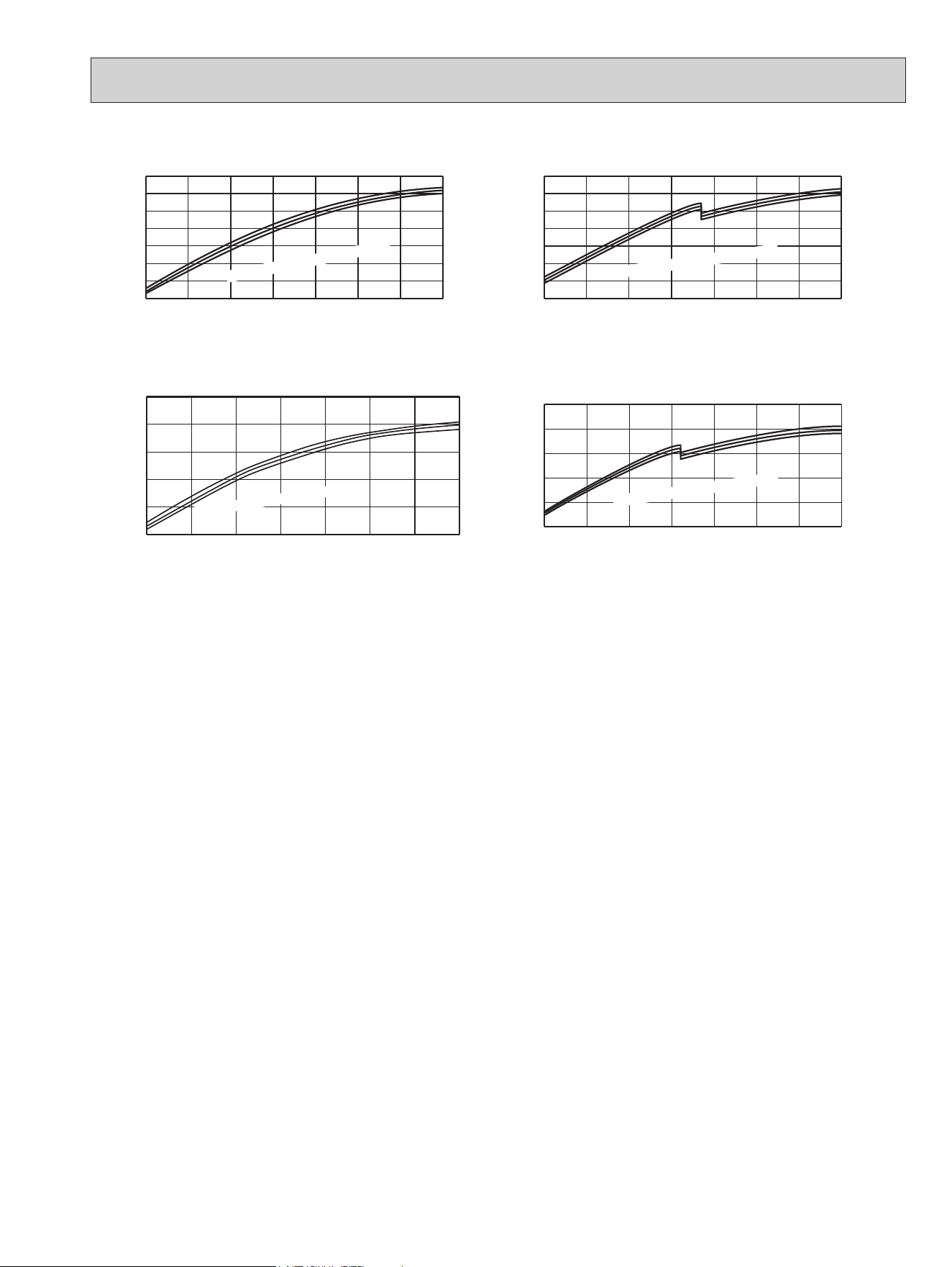
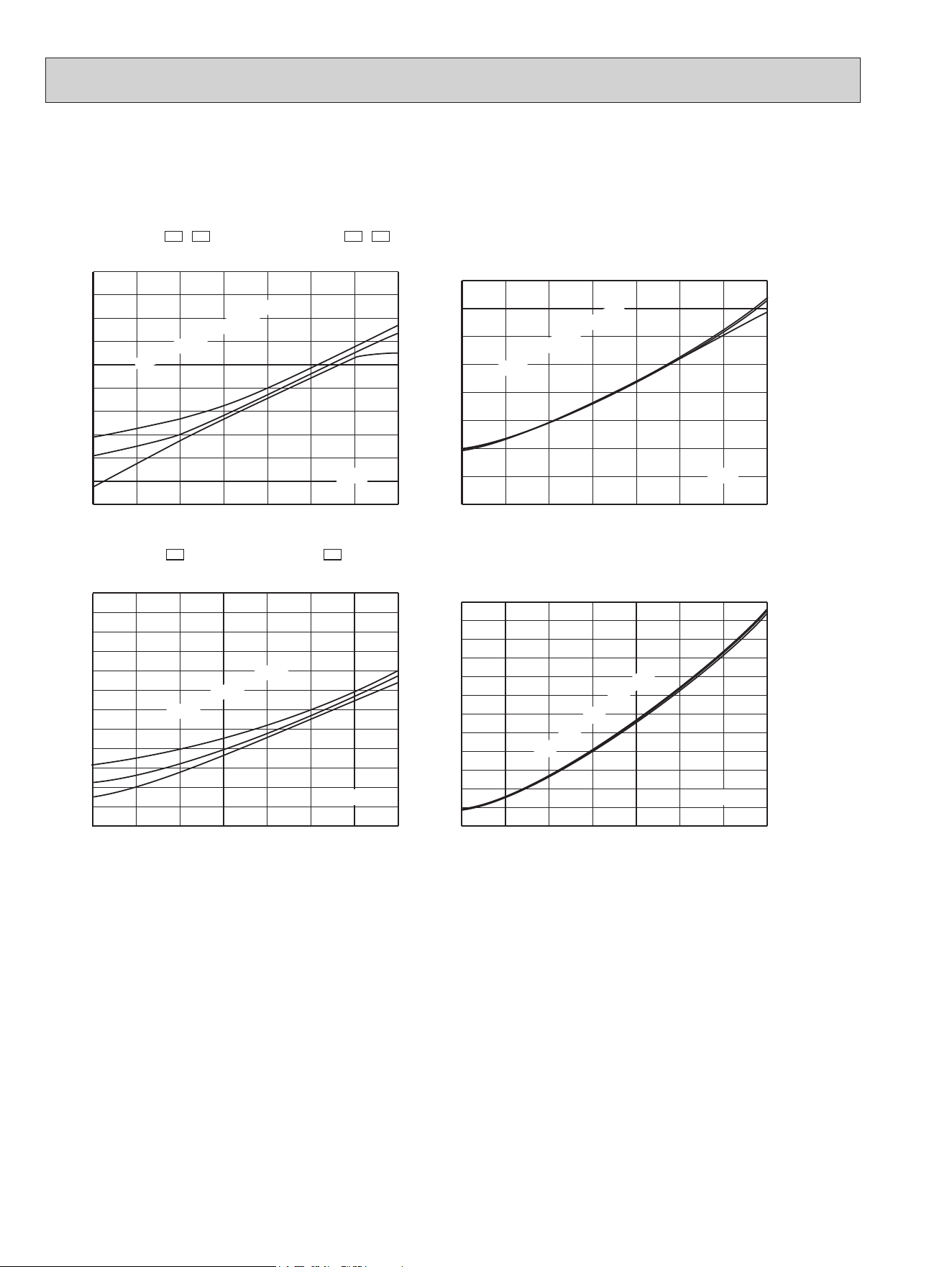
MUZ-GL18NA
MUZ-GL24NA
This value of frequency is not the same as the actual frequency in operating. Refer to 7-5 and 7-6 for the relationships
between frequency and capacity.
75
70
65
-5 5 15 25 35 45 55
65
0.6
0.8
1.0
1.2
1.4
1.6
1.8
2.0
Indoor intake air DB temperature (°F)
= 646 CFM
Airflow
Outdoor intake air WB temperature (°F)
Total power consumption
(kW)
MUZ-GL18NAH
65
70
75
-5 5 15 25 35 45 55
65
0.6
0.8
1.0
1.2
1.4
1.6
1.8
2.0
Indoor intake air DB temperature (°F)
= 646 CFM
Airflow
Outdoor intake air WB temperature (°F)
Total power consumption
(kW)
75
70
65
0 10 20 30 40 50 60 70
1.0
1.4
1.8
2.2
2.6
3.0
Indoor intake air DB temperature (°F)
= 738 CFM
Airflow
Outdoor intake air WB temperature (°F)
Total power consumption
(kW)
MUZ-GL24NAH
65
70
75
0 10 20 30 40 50 60 70
1.0
1.4
1.8
2.2
2.6
3.0
Indoor intake air DB temperature (°F)
= 738 CFM
Airflow
Outdoor intake air WB temperature (°F)
Total power consumption
(kW)
OBH733J
30
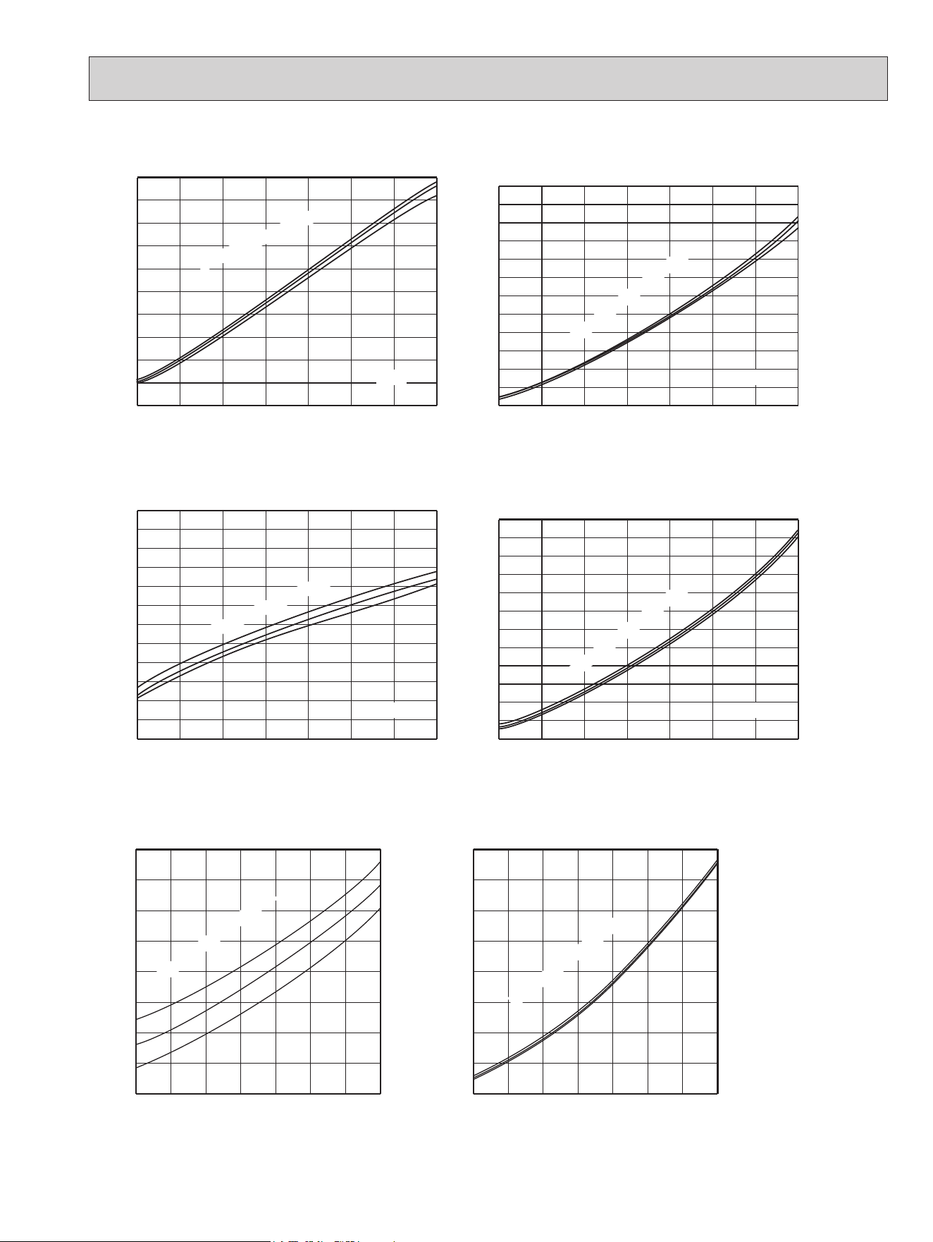
7-3. CONDENSING PRESSURE
Cooling
Data are based on the condition of indoor humidity 50 %.
Airflow should be set to High speed.
MUZ-GL09NA MUZ-GL09NAH MUY-GL09NA
MUZ-GL12NA MUZ-GL12NAH MUY-GL12NA
MUZ-GL15NA MUZ-GL15NAH MUY-GL15NA
65 70 75 80 85 90 95 100 105
200
250
300
350
400
450
(°F) (°F)
65 70 75 80 85 90 95 100 105
60
80
100
120
140
160
180
(PSIG)
Condensing pressure
Suction pressure
Outdoor ambient temperature
Indoor DB temperature (°F)
(PSIG)
Indoor DB temperature (°F)
Outdoor ambient temperature
86
80
75
70
86
80
75
70
65 70 75 80 85 90 95 100 105
200
250
300
350
400
450
500
(°F) (°F)
65 70 75 80 85 90 95 100 105
60
80
100
120
140
160
180
(PSIG)
Condensing pressure
Suction pressure
Outdoor ambient temperature
Indoor DB temperature (°F)
(PSIG)
Indoor DB temperature (°F)
Outdoor ambient temperature
86
80
75
70
86
80
75
70
OBH733J
31
MUZ-GL18NA MUZ-GL18NAH MUY-GL18NA
MUZ-GL24NA MUZ-GL24NAH MUY-GL24NA
65 70 75 80 85 90 95 100 105
200
250
300
350
400
450
500
(°F) (°F)
65 70 75 80 85 90 95 100 105
80
100
120
140
160
180
(PSIG)
Condensing pressure
Suction pressure
Outdoor ambient temperature
Indoor DB temperature (°F)
(PSIG)
Indoor DB temperature (°F)
Outdoor ambient temperature
86
80
75
70
86
80
75
70
(PSIG)
6870 75 80 85 90
95
100 105
(°F)
270
300
330
360
390
420
450
480
(PSIG)
6870 75 80 85 90
95
100 105
(°F)
110
120
130
140
150
160
170
180
Condensing pressure
86
80
75
70
Suction pressure
Indoor DB temperature (°F)
Outdoor ambient temperature
86
80
75
70
Indoor DB temperature (°F)
Outdoor ambient temperature
OBH733J
32
Heating
Data are based on the condition of outdoor humidity 75%.
Airflow should be set to High speed.
Data are for heating operation without any frost.
MUZ-GL09NA -
U1
,
U2
MUZ-GL09NAH -
U1
,
U2
75
70
65
75
70
65
(PSIG)
Condensing pressure
Outdoor ambient temperature
(°F) (°F)
(PSIG)
Suction pressure
Outdoor ambient temperature
5 15 25 35 45 55 65 75
200
250
300
350
400
450
58Hz
Indoor DB temperature (°F)
5 15 25 35 45 55 65 75
0
50
100
150
200
Indoor DB temperature (°F)
58Hz
75
70
65
75
70
65
(PSIG)
Condensing pressure
Outdoor ambient temperature
(°F) (°F)
(PSIG)
Suction pressure
Outdoor ambient temperature
5 15 25 35 45 55 65 75
200
250
300
350
400
450
500
58Hz
Indoor DB temperature (°F)
5 15 25 35 45 55 65 75
40
65
90
115
140
165
190
Indoor DB temperature (°F)
58Hz
MUZ-GL09NA -
U8
MUZ-GL09NAH -
U8
MUZ-GL12NA MUZ-GL12NAH
OBH733J
33
MUZ-GL15NA MUZ-GL15NAH
75
70
65
75
70
65
(PSIG)
Condensing pressure
Outdoor ambient temperature
(°F) (°F)
(PSIG)
Suction pressure
Outdoor ambient temperature
5 15 25 35 45 55 65 75
250
300
350
400
450
500
58Hz
Indoor DB temperature (°F)
5 15 25 35 45 55 65 75
40
65
90
115
140
165
190
Indoor DB temperature (°F)
58Hz
MUZ-GL18NA MUZ-GL18NAH
MUZ-GL24NA MUZ-GL24NAH
75
70
65
75
70
65
(PSIG)
Condensing pressure
Outdoor ambient temperature
(°F) (°F)
(PSIG)
Suction pressure
Outdoor ambient temperature
5 15 25 35 45 55 65 75
250
300
350
400
450
500
550
81Hz
Indoor DB temperature (°F)
5 15 25 35 45 55 65 75
50
75
100
125
150
175
200
Indoor DB temperature (°F)
81Hz
5 15 25 35 45 55 65 75(°F) 75(°F)
250
275
300
325
350
375
400
425
450
5 15 25 35 45 55 65
50
70
90
110
130
150
170
190
210
Indoor DB temperature (°F)
Condensing pressure
Outdoor ambient temperature
(PSIG) (PSIG)
75
70
65
58Hz
Indoor DB temperature (°F)
Suction pressure
Outdoor ambient temperature
75
70
65
58Hz
OBH733J
34
7-4. STANDARD OPERATION DATA
Model
MSZ-GL09NA -
U1
MSZ-GL09NA -
U2
MSZ-GL09NA
-
U8
MSY-GL09NA
-
U1
MSY-GL09NA
-
U2
Item Unit Cooling Heating Cooling Heating Cooling
Total
Capacity Btu/h 9,000 10,900 9,000 10,900 9,000
SHF — 0.82 — 0.82 — 0.82
Input kW 0.585 0.72 0.585 0.72 0.585
Rated Hz 59.5 72 48 59 59.5
Electrical circuit
Indoor unit MSZ-GL09NA MSZ-GL09NA MSY-GL09NA
Power supply V, phase, Hz 208/230, 1, 60 208/230, 1, 60 208/230, 1, 60
Input kW 0.022 0.023 0.022 0.023 0.022
Fan motor current A 0.24/0.22 0.25/0.23 0.24/0.22 0.25/0.23 0.24/0.22
Outdoor unit
MUZ-GL09NA -
U1
,
U2
MUZ-GL09NAH -
U1
,
U2
MUZ-GL09NA -
U8
MUZ-GL09NAH -
U8
MUY-
GL09NA
-
U1
MUY-
GL09NA
-
U2
Power supply V, phase, Hz 208/230, 1, 60 208/230, 1, 60 208/230, 1, 60
Input kW 0.563 0.697 0.563 0.697 0.563
Comp. current A 2.67/2.41 3.25/2.94 2.45/2.21 3.05/2.76 2.63/2.37
Fan motor current A 0.36/0.33 0.34/0.31 0.36/0.33 0.34/0.31 0.36/0.33
Refrigerant circuit
Condensing pressure PSIG 357 345 358 349 358
Suction pressure PSIG 151 107 149 108 149
Discharge temperature ˚F 146 156 148 155 154
Condensing temperature ˚F 108 102 108 104 108
Suction temperature ˚F 61 44 63 44 66
Comp. shell bottom temperature ˚F 144 154 140 144 152
Ref. pipe length ft. 25 25 25
Refrigerant charge (R410A) 2 lb 5 oz. 2 lb 9 oz. 2 lb 9 oz. 2 lb 5 oz.
Indoor unit
Intake air temperature
DB ˚F 80 70 80 70 80
WB ˚F 67 60 67 60 67
Discharge air temperature
DB ˚F 59 99 59 99 59
WB ˚F 56 — 56 — 56
Fan speed (High) rpm 1,020 1,040 1,020 1,040 1,020
Airow (High) CFM 367 (Wet) 413 367 (Wet) 413 367 (Wet)
Outdoor unit
Intake air temperature
DB ˚F 95 47 95 47 95
WB ˚F — — — — —
Fan speed rpm 900 860 900 860 900
Airow CFM 1,229 1,172 1,229 1,172 1,229
OBH733J
35
Model MSZ-GL12NA
MSY-GL12NA
MSZ-GL15NA
MSY-GL15NA
Item Unit Cooling Heating Cooling Cooling Heating Cooling
Total
Capacity Btu/h 12,000 14,400 12,000 14,000 18,000 14,000
SHF — 0.77 — 0.77 0.78 — 0.78
Input kW 0.920 1.10 0.920 1.080 1.60 1.080
Rated Hz 70 77 70 56.5 74 56.5
Electrical circuit
Indoor unit MSZ-GL12NA
MSY-GL12NA
MSZ-GL15NA
MSY-GL15NA
Power supply V, phase, Hz 208/230, 1, 60
208/230, 1, 60
208/230, 1, 60
208/230, 1, 60
Input kW 0.022 0.023 0.022 0.043 0.030 0.043
Fan motor current A 0.24/0.22 0.25/0.23 0.24/0.22 0.43/0.39 0.34/0.31 0.43/0.39
Outdoor unit
MUZ-GL12NA
MUZ-GL12NAH
MUY-GL12NA
MUZ-GL15NA
MUZ-GL15NAH
MUY-GL15NA
Power supply V, phase, Hz 208/230, 1, 60
208/230, 1, 60
208/230, 1, 60
208/230, 1, 60
Input kW 0.898 1.077 0.898 1.037 1.570 1.037
Comp. current A 4.01/3.62 4.86/4.39 4.01/3.62 4.51/4.08 7.11/6.43 4.51/4.08
Fan motor current A 0.41/0.37 0.40/0.36 0.41/0.37 0.41/0.37 0.40/0.36 0.41/0.37
Refrigerant circuit
Condensing pressure PSIG 380 402 380 396 427 396
Suction pressure PSIG 133 106 133 138 98 138
Discharge temperature ˚F 166 167 166 168 178 168
Condensing temperature ˚F 112 115 112 115 120 115
Suction temperature ˚F 60 35 60 61 31 61
Comp. shell bottom temperature ˚F 152 150 152 152 158 152
Ref. pipe length ft. 25 25 25 25
Refrigerant charge (R410A) 2 lb 9 oz. 2 lb 9 oz. 2 lb 9 oz. 2 lb 9 oz.
Indoor unit
Intake air temperature
DB ˚F 80 70 80 80 70 80
WB ˚F 67 60 67 67 60 67
Discharge air temperature
DB ˚F 57 110 57 58 114 58
WB ˚F 55 — 55 56 — 56
Fan speed (High) rpm 1,020 1,040 1,020 1,280 1,140 1,280
Airow (High) CFM 367 (Wet) 413 367 (Wet) 498 (Wet) 463 498 (Wet)
Outdoor unit
Intake air temperature
DB ˚F 95 47 95 95 47 95
WB ˚F — 43 — — 43 —
Fan speed rpm 900 860 900 910 900 910
Airow CFM 1,229 1,172 1,229 1,243 1,229 1,243
OBH733J
36
Model MSZ-GL18NA
MSY-GL18NA
MSZ-GL24NA
MSY-GL24NA
Item Unit Cooling Heating Cooling Cooling Heating Cooling
Total
Capacity Btu/h 18,000 21,600 18,000 22,500 27,600 22,500
SHF — 0.87 — 0.87 0.75 — 0.75
Input kW 1.34 1.68 1.34 1.80 2.34 1.80
Rated Hz 69 81 69 67.5 82.0 67.5
Electrical circuit
Indoor unit MSZ-GL18NA
MSY-GL18NA
MSZ-GL24NA
MSY-GL24NA
Power supply V, phase, Hz 208/230, 1, 60
208/230, 1, 60
208/230, 1, 60
208/230, 1, 60
Input kW 0.045 0.045 0.058 0.058
Fan motor current A 0.46/0.42 0.46/0.42 0.56/0.51 0.56/0.51
Outdoor unit
MUZ-GL18NA
MUZ-GL18NAH
MUY-GL18NA
MUZ-GL24NA
MUZ-GL24NAH
MUY-GL24NA
Power supply V, phase, Hz 208/230, 1, 60
208/230, 1, 60
208/230, 1, 60
208/230, 1, 60
Input kW 1.295 1.635 1.295 1.742 2.282 1.742
Comp. current A 5.01/4.53 6.67/6.03 5.01/4.53 7.01/6.34 9.59/8.67 7.01/6.34
Fan motor current A 1.05/0.95 1.05/0.95 1.05/0.95 1.16/1.05 1.13/1.02 1.16/1.05
Refrigerant circuit
Condensing pressure PSIG 377 391 377 395 405 395
Suction pressure PSIG 144 103 144 141 102 141
Discharge temperature ˚F 149 178 149 158 171 158
Condensing temperature ˚F 111 111 111 115 115 115
Suction temperature ˚F 51 43 51 52 33 52
Comp. shell bottom temperature ˚F 134 160 134 140 148 140
Ref. pipe length ft. 25 25 25 25
Refrigerant charge (R410A) 3 lb 9 oz. 3 lb 9 oz. 4 lb 3 oz. 4 lb 3 oz.
Indoor unit
Intake air temperature
DB ˚F 80 70 80 80 70 80
WB ˚F 67 60 67 67 60 67
Discharge air temperature
DB ˚F 52 111 52 56 111 56
WB ˚F 51 — 51 53 — 53
Fan speed (High) rpm 1,170 1,170 1,170 1,300 1,300 1,300
Airow (High) CFM 581 (Wet) 646 581 (Wet) 634 (Wet) 738 634 (Wet)
Outdoor unit
Intake air temperature
DB ˚F 95 47 95 95 47 95
WB ˚F — 43 — — 43 —
Fan speed rpm 810 810 810 840 810 840
Airow CFM 1,691 1,691 1,691 1,769 1,701 1,769
OBH733J
37
Capacity correction factors
Input correction factors
Correction of Cooling capacity
The operational frequency of compressor
Correction of Cooling total input
The operational frequency of compressor
(Hz) (Hz)
Capacity correction factors
Input correction factors
Input correction factors
Capacity correction factors
Correction of Cooling capacity
The operational frequency of compressor
Correction of Cooling total input
The operational frequency of compressor
Correction of Heating total input
The operational frequency of compressor
Correction of Heating capacity
The operational frequency of compressor
(Hz) (Hz)
(Hz) (Hz)
Capacity correction factors
Input correction factors
Input correction factors
Capacity correction factors
Correction of Cooling capacity
The operational frequency of compressor
Correction of Cooling total input
The operational frequency of compressor
Correction of Heating total input
The operational frequency of compressor
Correction of Heating capacity
The operational frequency of compressor
(Hz) (Hz)
(Hz) (Hz)
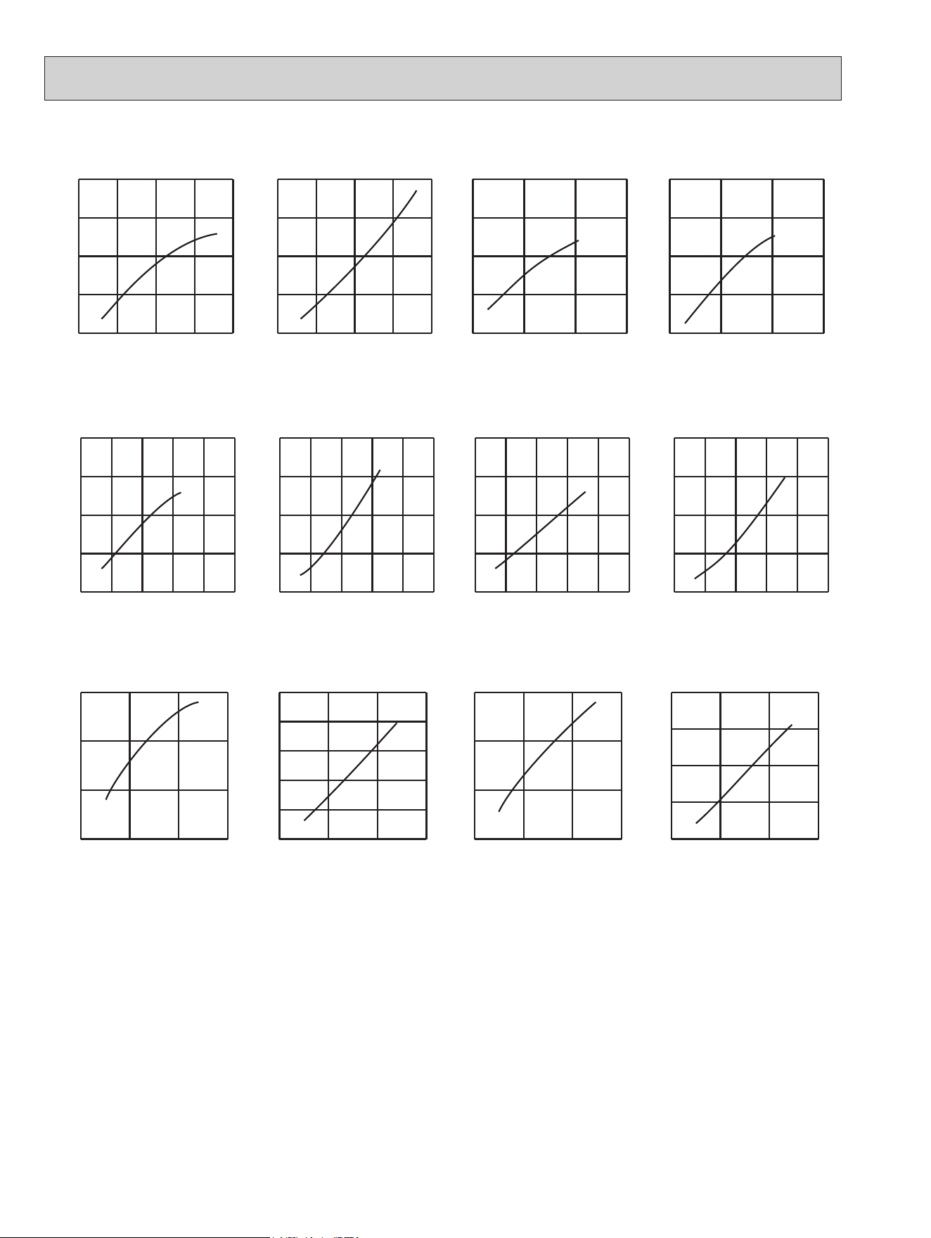
0 25 50 75 100
0.5
1.0
1.5
2.0
0 25 50 75 100
0.5
1.0
1.5
2.0
0 25 50 75 100
0.5
1.0
1.5
2.0
0 25 50 75 100
0.5
1.0
1.5
2.0
0 25 50 75 100
0.5
1.0
1.5
2.0
0 25 50 75 100
0.5
1.0
1.5
2.0
0 25 50 75 100
0.5
1.0
1.5
2.0
0 25 50 75 100
0.5
1.0
1.5
2.0
0 25 50 75 100
0.5
1.0
1.5
2.0
0 25 50 75 100
0.5
1.0
1.5
2.0
0 25 50 75 100
0.5
1.0
1.5
2.0
MUZ-GL09NA -
U1
,
U2
MUZ-GL09NAH-
U1
,
U2
MUZ-GL09NA -
U8
MUZ-GL09NAH -
U8
MUZ-GL12NA MUZ-GL12NAH MUY-GL12NA MUZ-GL12NA MUZ-GL12NAH
0 25 50 75 100
0.5
1.0
1.5
2.0
0 50 100 150
0.5
1.0
1.5
2.0
0 50 100 150
0.5
1.0
1.5
2.0
MUY-GL09NA
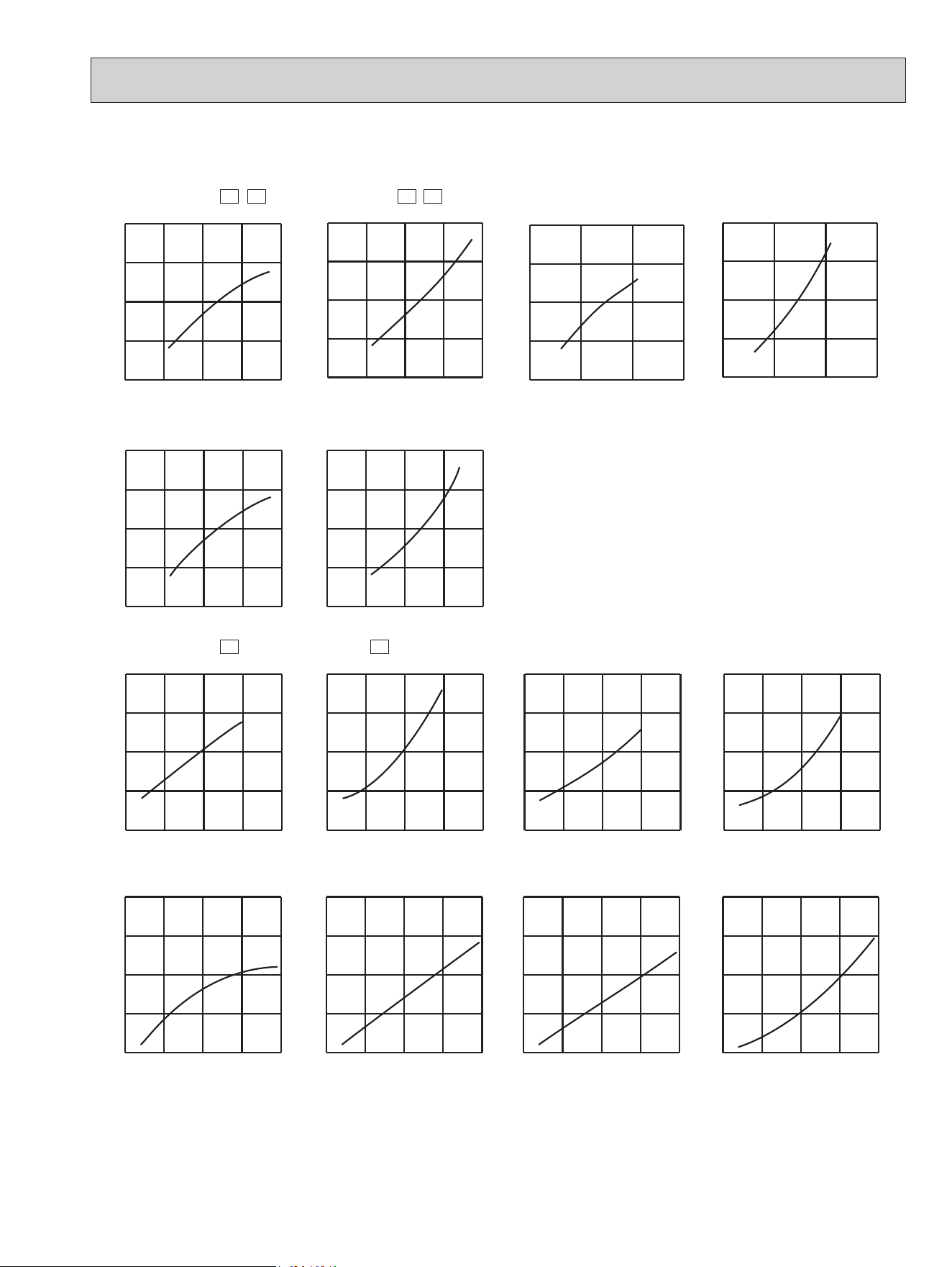
7-5. CAPACITY AND INPUT CORRECTION BY INVERTER OUTPUT FREQUENCY
OBH733J
38
MUZ-GL24NA MUZ-GL24NAH MUY-GL24NA MUZ-GL24NA MUZ-GL24NAH
Capacity correction factors
Capacity correction factors
Correction of Cooling capacity
The operational frequency of compressor
Correction of Cooling total input
The operational frequency of compressor
Correction of Heating total input
The operational frequency of compressor
Correction of Heating capacity
The operational frequency of compressor
0 50 100 150(Hz)
0.5
1.0
1.5
0 50 100 150(Hz)
0.5
1.0
1.5
2.0
2.5
0 50 100 150(Hz)
0.5
1.0
1.5
0 50 100 150(Hz)
0.5
1.0
1.5
2.0
Capacity correction factors
Input correction factors
Input correction factors
Capacity correction factors
Correction of Cooling capacity
The operational frequency of compressor
Correction of Cooling total input
The operational frequency of compressor
Correction of Heating total input
The operational frequency of compressor
Correction of Heating capacity
The operational frequency of compressor
(Hz) (Hz)
(Hz) (Hz)
0
30 60 90 120 150
0.5
1.0
1.5
2.0
0
30 60 90 120 150
0.5
1.0
1.5
2.0
0
30 60 90 120 150
0.5
1.0
1.5
2.0
0
30 60 90 120 150
0.5
1.0
1.5
2.0
MUZ-GL18NA MUZ-GL18NAH MUY-GL18NA MUZ-GL18NA MUZ-GL18NAH
Capacity correction factors
Input correction factorsInput correction factors
Input correction factors
Input correction factors
Capacity correction factors
Correction of Cooling capacity
The operational frequency of compressor
Correction of Cooling total input
The operational frequency of compressor
Correction of Heating total input
The operational frequency of compressor
Correction of Heating capacity
The operational frequency of compressor
(Hz) (Hz)
(Hz) (Hz)
0 25 50 75 100
0.5
1.0
1.5
2.0
0 25 50 75 100
0.5
1.0
1.5
2.0
0 50 100
150
0.5
1.0
1.5
2.0
0 50 100
150
0.5
1.0
1.5
2.0
MUZ-GL15NA MUZ-GL15NAH MUY-GL15NA MUZ-GL15NA MUZ-GL15NAH
7-6. HOW TO OPERATE FIXED-FREQUENCY OPERATION (Test run operation)
1. Press EMERGENCY OPERATION switch to start COOL or HEAT mode (COOL: Press once, HEAT: Press twice).
2. Test run operation starts and continues to operate for 30 minutes.
3. Compressor operates at rated frequency in COOL mode or 58 Hz in HEAT mode.
4. Indoor fan operates at High speed.
5. After 30 minutes, test run operation finishes and EMERGENCY OPERATION starts (operation frequency of compressor var-
ies).
6. To cancel test run operation (EMERGENCY OPERATION), press EMERGENCY OPERATION switch or any button on the
remote controller.
OBH733J
39
8
ACTUATOR CONTROL
8-2. R.V. COIL CONTROL (MUZ)
Heating
.................
ON
Cooling
.................
OFF
Dry
....................
OFF
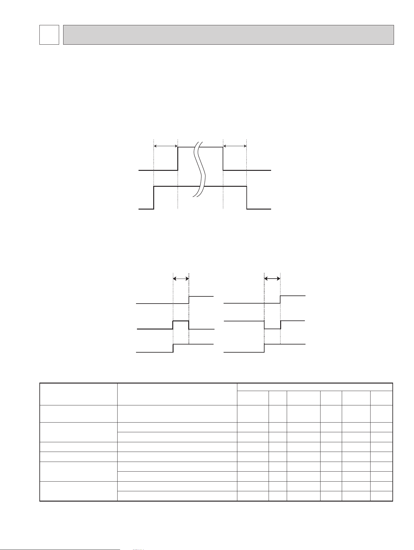
NOTE: The 4-way valve reverses for 5 seconds right before startup of the compressor.
ON
OFF
ON
OFF
Outdoor fan
motor
Compressor
5 seconds 15 seconds
8-1. OUTDOOR FAN MOTOR CONTROL
The fan motor turns ON/OFF, interlocking with the compressor.
[ON] The fan motor turns ON 5 seconds before the compressor starts up.
[OFF] The fan motor turns OFF 15 seconds after the compressor has stopped running.
8-3. RELATION BETWEEN MAIN SENSOR AND ACTUATOR
Sensor Purpose
Actuator
Compressor
LEV
Outdoor fan
motor
R.V.coil
Indoor fan
motor
Defrost
heater *
Discharge temperature
thermistor
Protection
○ ○
Indoor coil temperature
thermistor
Cooling: Coil frost prevention
○
Heating: High pressure protection
○ ○
Defrost thermistor (MUZ) Heating: Defrosting
○ ○ ○ ○ ○
Fin temperature thermistor Protection
○ ○
Ambient temperature
thermistor
Cooling: Low ambient temperature operation
○ ○ ○
Heating: Defrosting (Heater)
○
Outdoor heat exchanger tem-
perature thermistor
Cooling: Low ambient temperature operation
○ ○ ○
Cooling: High pressure protection
○ ○ ○
*. MUZ-GL•NAH only.
ON
OFF
Compressor
Outdoor fan
motor
R.V.coil
ON
OFF
ON
OFF
<COOL>
5 seconds
<HEAT>
5 seconds
MUZ-GL09NA MUZ-GL09NAH MUY-GL09NA
MUZ-GL12NA MUZ-GL12NAH MUY-GL12NA
MUZ-GL15NA MUZ-GL15NAH MUY-GL15NA
MUZ-GL18NA MUZ-GL18NAH MUY-GL18NA
MUZ-GL24NA MUZ-GL24NAH MUY-GL24NA
OBH733J
40
SERVICE FUNCTIONS
9
9-1. CHANGE IN DEFROST SETTING (MUZ)
Changing defrost finish temperature
<JS> To change the defrost finish temperature, cut/solder the JS wire of the outdoor inverter P.C. board (Refer to 10-6.1.).
Jumper
Defrost nish temperature
MUZ-GL09/12/15NA
MUZ-GL09/12/15NAH
MUZ-GL18/24NA
MUZ-GL18/24NAH
JS
Soldered
(Initial setting)
41°F (5°C) 50°F (10°C)
None
(Cut)
50°F (10°C) 64°F (18°C)
9-2. PRE-HEAT CONTROL SETTING (MUZ)
MUZ-GL09/12/15/18
When moisture gets into the refrigerant cycle, it may interfere with the startup of the compressor at low outside tempera-
ture. The pre-heat control prevents this interference. The pre-heat control turns ON when the discharge temperature ther-
mistor is 68°F (20°C) or below. When the pre-heat control turns ON, the compressor is energized. (About 50 W)
MUZ-GL24
Prolonged low load operation, in which the thermostat is OFF for a long time, at low outside temperature [32°F (0°C) or
less] may cause the following troubles. The pre-heat control prevents those troubles.
1) If moisture gets into the refrigerant cycle and freezes, it may interfere the startup of the compressor.
2) If liquid refrigerant collects in the compressor, a failure in the compressor may occur.
The pre-heat control turns ON when the compressor temperature is 68°F (20°C) or below. When the pre-heat control
turns ON, the compressor is energized. (About 70 W)
Pre-heat control setting
<JK>
ON: To activate the pre-heat control, cut JK wire of the inverter P.C. board.
OFF: To deactivate the pre-heat control, solder JK wire of the inverter P.C. board.
(Refer to 10-6.1)
Jumper
Pre-heat control setting
MUZ-GL09/12/15/18NA
MUZ-GL09/12/15/18NAH
MUZ-GL24NA
MUZ-GL24NAH
JK
Soldered
Deactivated
(Initial setting)
Deactivated
Cut Activated
Activated
(Initial setting)
NOTE: When the inverter P.C. board is replaced, check the JK wire, and cut/solder them if necessary.
MUZ-GL09NA MUZ-GL09NAH MUY-GL09NA
MUZ-GL12NA MUZ-GL12NAH MUY-GL12NA
MUZ-GL15NA MUZ-GL15NAH MUY-GL15NA
MUZ-GL18NA MUZ-GL18NAH MUY-GL18NA
MUZ-GL24NA MUZ-GL24NAH MUY-GL24NA
OBH733J

41
10
TROUBLESHOOTING
10-1. CAUTIONS ON TROUBLESHOOTING
1. Before troubleshooting, check the following
1) Check the power supply voltage.
2) Check the indoor/outdoor connecting wire for miswiring.
2. Take care of the following during servicing
1) Before servicing the air conditioner, be sure to turn OFF the main unit first with the remote controller, then after con-
firming the horizontal vane is closed, turn off the breaker and/or disconnect the power plug.
2) Be sure to turn OFF the power supply before removing the front panel, the cabinet, the top panel, and the electronic
control P.C. board.
3) When removing the electrical parts, be careful of the residual voltage of smoothing capacitor.
4) When removing the electronic control P.C. board, hold the edge of the board with care NOT to apply stress on the
components.
5) When connecting or disconnecting the connectors, hold the connector housing. DO NOT pull the lead wires.
3. Troubleshooting procedure
1)
Check if the OPERATION INDICATOR lamp on the indoor unit is blinking on and off to indicate an abnormality. To make
sure, check how many times the OPERATION INDICATOR lamp is blinking on and off before starting service work. (See
the service manual of the indoor unit for a description of those failure codes.)
2) Before servicing, verify that all connectors and terminals are connected properly.
3) When the electronic control P.C. board seems to be defective, check for disconnection of the copper foil pattern and
burnt or discolored components.
4) Refer to 10-2 and 10-3.
Lead wiring
<Incorrect>
Connector housing
<Correct>
MUZ-GL09NA MUZ-GL09NAH MUY-GL09NA
MUZ-GL12NA MUZ-GL12NAH MUY-GL12NA
MUZ-GL15NA MUZ-GL15NAH MUY-GL15NA
MUZ-GL18NA MUZ-GL18NAH MUY-GL18NA
MUZ-GL24NA MUZ-GL24NAH MUY-GL24NA
OBH733J
42
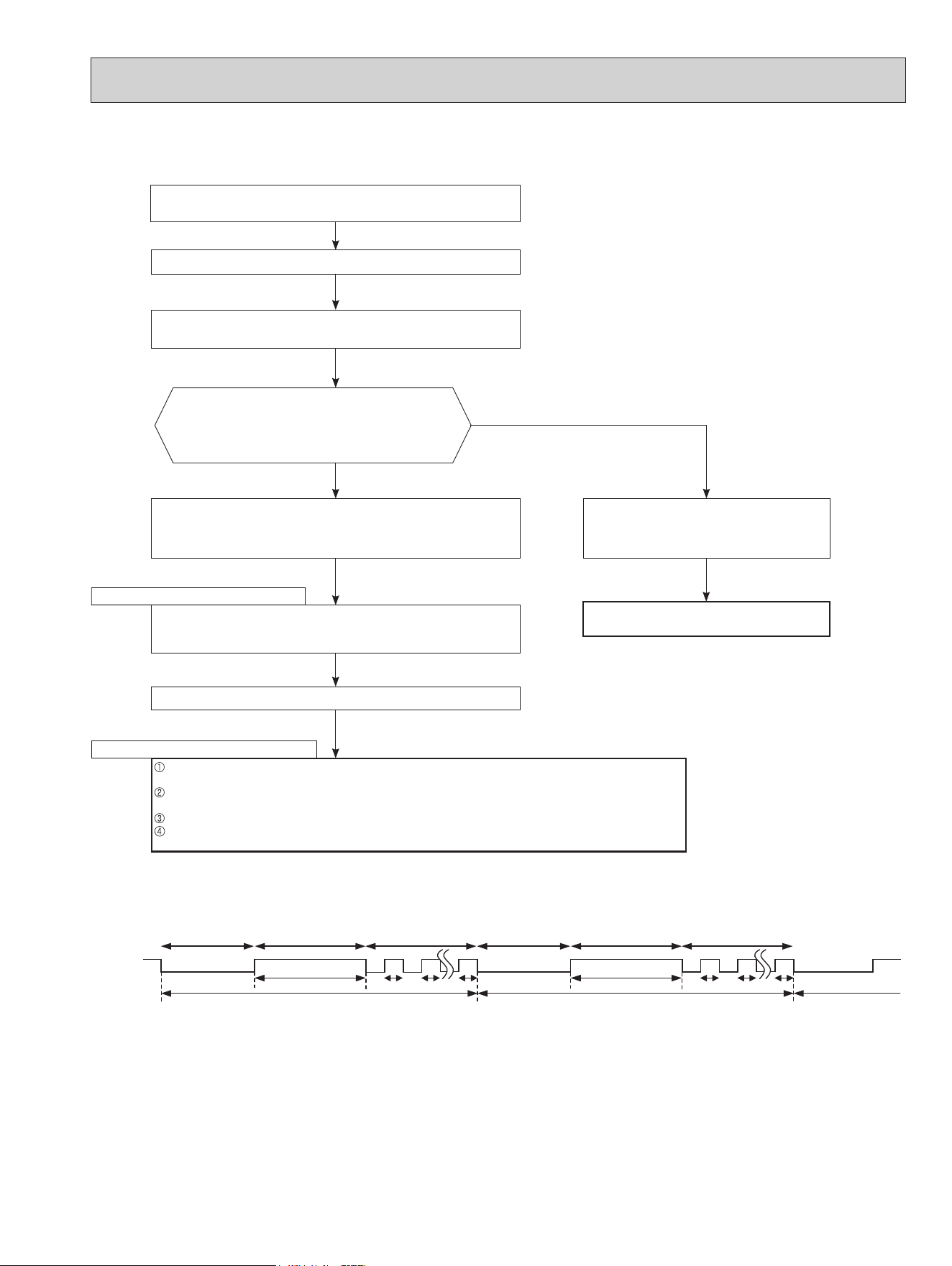
Outline of the function
This air conditioner can memorize the abnormal condition which has occurred once.
Even though LED indication listed on the troubleshooting check table (10-3.) disappears, the memorized failure details can be recalled.
10-2. FAILURE MODE RECALL FUNCTION
1. Flow chart of failure mode recall function
for the indoor/outdoor unit
NOTE: 1. Make sure to release the failure mode recall function after it is set up, otherwise the unit cannot operate properly.
2. If the abnormal condition is not deleted from the memory, the last abnormal condition is kept memorized.
Does the upper lamp of the OPERATION INDICATOR lamp on
the indoor unit blink at the interval of 0.5 seconds?
Blinks: Either indoor or outdoor unit is abnormal. Beep is
emitted at the same timing as the blinking of the upper
lamp of the OPERATION INDICATOR lamp. *2
Indoor unit is normal.
But the outdoor unit might be abnormal because there are some abnor-
malities that cannot be recalled with this way.
Check if outdoor unit is abnormal according to the detailed outdoor unit
failure mode recall function. (Refer to 10-2.2)
No
Yes
The cause of abnormality cannot be found because the abnormality does not recur.
Setting up the failure mode recall function
Turn ON the power supply.
<Preparation of the remote controller>
While pressing OPERATION SELECT button and TOO COOL button on the remote
controller at the same time, press RESET button.
First, release RESET button.
Hold down the other 2 buttons for another 3 seconds. Make sure that the indicators on
the LCD screen shown in the right gure are all displayed. Then release the buttons.
Press STOP/OPERATE (OFF/ON) button of the remote controller (the set temperature
is displayed) with the remote controller headed towards the indoor unit. *1
Judgment of indoor/outdoor abnormality
Before blinking, does the upper lamp of the OPERATION
INDICATOR lamp stay ON for 3 seconds?
When it stays ON for 3 seconds (without beep): The outdoor unit
is abnormal.
The indoor unit is abnormal.
Check the blinking pattern, and identify the abnormal point by referring to the
table of indoor unit failure mode recall function. (Refer to indoor unit service
manual.) Make sure to check at least 2 consecutive blinking cycles. *2
Releasing the failure mode recall function
Release the failure mode recall function by the following procedures.
Turn OFF the power supply and turn it ON again.
Press RESET button of the remote controller.
The outdoor unit is abnormal.
Check the blinking pattern, and identify the abnormal point by referring
to the table of outdoor unit failure mode recall function. (Refer to 10-2.3)
Make sure to check at least 2 consecutive blinking cycles. *3
Repair the failure parts.
Deleting the memorized abnormal condition
After repairing the unit, recall the failure mode again according to "Setting up the failure mode recall
function" mentioned above.
Press STOP/OPERATE (OFF/ON) button of the remote controller (the set temperature is displayed)
with the remote controller headed towards the indoor unit.
Press EMERGENCY OPERATION switch so that the memorized abnormal condition is deleted.
Release the failure mode recall function according to "Releasing the failure mode recall function"
mentioned above.
Operational procedure
Yes
(Blinks)
No
(OFF)
*1. Regardless of normal or abnormal condition,
a short beep is emitted once the signal is
received.
*2. Blinking pattern when the indoor unit is abnormal:
*3.Blinking pattern when the outdoor unit is abnormal:
ON
OFF
Beeps
Repeated cycle Repeated cycle
ON
OFF
No beep Beeps
Repeated cycle
2.5-second OFF
Blinking at 0.5-
second interval
2.5-second OFF 3-second ON
Blinking at 0.5-
second interval
Beeps
Repeated cycle
2.5-second OFF
Blinking at 0.5-
second interval
No beep Beeps
Repeated cycle
2.5-second OFF 3-second ON
Blinking at 0.5-
second interval
Repeated cycle
Beeps
MSZ-GL18NA
MSY-GL18NA
MSZ-GL24NA
MSY-GL24NA
MSZ-GL06/09/12/15NA
MSY-GL09/12/15NA
MSZ type
MSY type
OBH733J
43
2. Flow chart of the detailed outdoor unit failure mode recall function
*2.Blinking pattern when outdoor unit is abnormal:
ON
OFF
No beep
Beeps
Repeated cycle
2.5-second OFF 3-second ON
Blinking at 0.5-
second interval
No beep Beeps
Repeated cycle
2.5-second OFF 3-second ON
Blinking at 0.5-
second interval
Repeated cycle
Does the upper lamp of the OPERATION INDICATOR
lamp on the indoor unit blink at the interval of 0.5 seconds?
Blinks: The outdoor unit is abnormal. Beep is emitted at
the same timing as the blinking of the upper lamp
of the OPERATION INDICATOR lamp. *2
Yes
(Blinks
)
No
(OFF)
The outdoor unit might be abnormal.
Check if outdoor unit is abnormal according to the following procedures.
Operational procedure
Make sure that the remote controller is set to the failure mode recall function.
With the remote controller headed towards the indoor unit, press TOO
COOL button to adjust the set temperature to 77°F (25°C). *1
*
1. Regardless of normal or abnormal condition, 2 short
beeps are emitted as the signal is received.
The outdoor unit is abnormal.
Check the blinking pattern, and identify the abnormal point by referring to
the table of outdoor unit failure mode recall function (10-2.3.).
Make sure to check at least 2 consecutive blinking cycles. *2
Releasing the failure mode recall function
Release the failure mode recall function by the following procedures.
Turn OFF the power supply and turn it ON again.
Press RESET button of the remote controller.
Repair the failure parts.
The outdoor unit is normal.
Release the failure mode recall function accord-
ing to the left mentioned procedure.
Deleting the memorized abnormal condition
After repairing the unit, recall the failure mode again according to "Setting up the failure mode recall
function" (10-2.1.).
Press STOP/OPERATE (OFF/ON) button of the remote controller (the set temperature is displayed) with
the remote controller headed towards the indoor unit.
Press EMERGENCY OPERATION switch so that the memorized abnormal condition is deleted.
Release the failure mode recall function according to "Releasing the failure mode recall function" men-
tioned above.
NOTE: 1. Make sure to release the failure mode recall function after it is set up, otherwise the unit cannot operate properly.
2. If the abnormal condition is not deleted from the memory, the last abnormal condition is kept memorized.
OBH733J
44
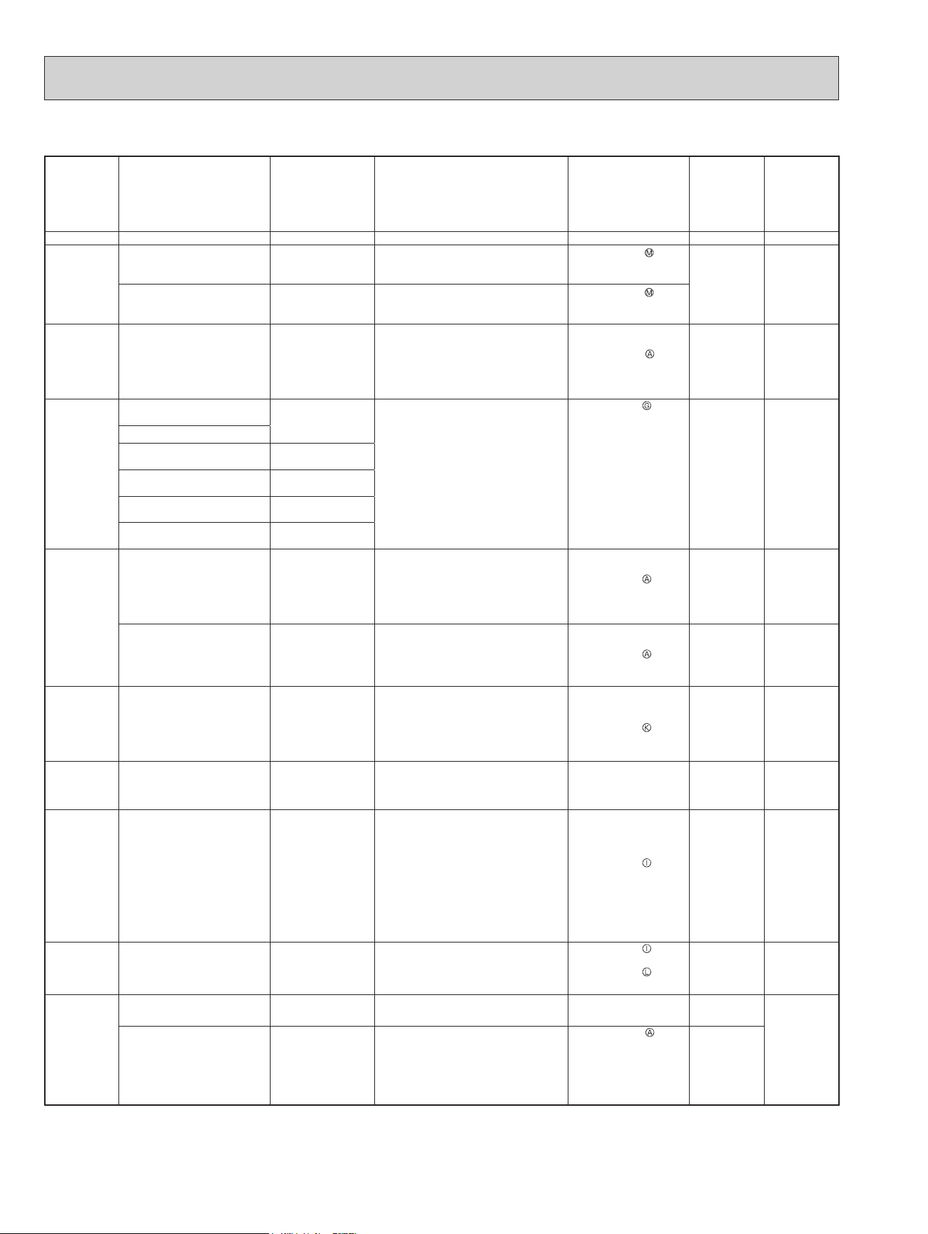
3. Table of outdoor unit failure mode recall function
The upper
lamp of the
OPERATION
INDICATOR
lamp
(Indoor unit)
Abnormal point
(Failure mode/protection)
LED indication
(Outdoor P.C. board)
Condition Remedy
Indoor/outdoor
unit failure
mode recall
function
Outdoor unit
failure mode
recall function
OFF None (Normal) — — — — —
1-time blink
2.5 seconds
OFF
Indoor/outdoor
communication, receiving
error
—
Any signals from the inverter P.C.
board cannot be received normally for
3 minutes.
•Refer to 10-5.
How
to check miswiring and
serial signal error.
○ ○
Indoor/outdoor
communication, receiving
error
—
Although the inverter P.C. board
sends signal "0", signal "1" has been
received 30 consecutive times.
•Refer to 10-5.
How
to check miswiring and
serial signal error.
2-time blink
2.5 seconds
OFF
Outdoor power system
—
Overcurrent protection cut-out
operates 3 consecutive times within
1 minute after the compressor gets
started.
•
Reconnect
connectors.
•
Refer to 10-5.
"How
to check inverter/
compressor".
•
Check stop valve.
○ ○
3-time blink
2.5 seconds
OFF
Discharge temperature
thermistor
1-time blink every
2.5 seconds
Thermistor shorts or opens during
compressor running.
•
Refer to 10-5.
"Check of outdoor
thermistors".
Defective outdoor
thermistors can be
identied by checking
the blinking pattern of
LED.
○ ○
Defrost thermistor
Fin temperature thermistor 3-time blink
2.5 seconds OFF
P.C. board temperature
thermistor
4-time blink
2.5 seconds OFF
Ambient temperature
thermistor
2-time blink
2.5 seconds OFF
Outdoor heat exchanger
temperature thermistor
—
4-time blink
2.5 seconds
OFF
Overcurrent 11-time blink
2.5 seconds OFF
Large current ows into the power
module (IC700) (MUZ-GL09/12/15/18,
MUY-GL09/12/15/18)/ IGBT module
(IC700) (MUZ-GL24, MUY-GL24).
•
Reconnect
compressor connector.
•
Refer to 10-5.
"How
to check inverter/
compressor".
•
Check stop valve.
—
○
Compressor synchronous
abnormality (Compressor
startup failure protection)
12-time blink
2.5 seconds OFF
Waveform of compressor current is
distorted.
•
Reconnect
compressor connector.
•
Refer to 10-5.
"How
to check inverter/
compressor".
—
○
5-time blink
2.5 seconds
OFF
Discharge temperature
—
Temperature of discharge temperature
thermistor exceeds 241°F (116°C),
compressor stops.
Compressor can restart if discharge
temperature thermistor reads
212°F (100°C) or less 3 minutes later.
•
Check refrigerant
circuit and refrigerant
amount.
•
Refer to 10-5.
"Check
of LEV".
—
○
6-time blink
2.5 seconds
OFF
High pressure
—
Temperature indoor coil thermistor
exceeds 158°F (70°C) in HEAT
mode. Temperature defrost thermistor
exceeds 158°F (70°C) in COOL mode.
•
Check refrigerant
circuit and refrigerant
amount.
•
Check stop valve.
—
○
7-time blink
2.5 seconds
OFF
Fin temperature/ P.C. board
temperature
7-time blink
2.5 seconds OFF
Temperature of the n temperature
thermistor on the inverter P.C. board
exceeds 167 - 187°F (75 - 86°C) (MUZ-
GL09/12/15/18, MUY-GL09/12/15/18)/167
- 176°F (75 - 80°C) (MUZ-GL24, MUY-
GL24), or temperature of P.C. board
temperature thermistor on the inverter
P.C. board exceeds 162 - 185°F (72
- 85°C) (MUZ-GL09/12/15/18, MUY-
GL09/12/15/18)/158 - 167°F (70 - 75°C)
(MUZ-GL24, MUY-GL24).
•
Check around outdoor
unit.
•
Check outdoor unit air
passage.
•
Refer to 10-5.
"Check
of outdoor fan motor".
—
○
8-time blink
2.5 seconds
OFF
Outdoor fan motor
—
Outdoor fan has stopped 3 times in a
row within 30 seconds after outdoor
fan startup.
•
Refer to 10-5.
"Check
of outdoor fan motor".
Refer to 10-5.
"Check
of inverter P.C. board".
—
○
9-time blink
2.5 seconds
OFF
Non-volatile memory data 5-time blink
2.5 seconds OFF
Non-volatile memory data cannot be
read properly.
•
Replace the inverter
P.C. board.
○
○
Power module (IC700)
(MUZ-
GL09/12/15/18
, MUY-
GL09/12/15/18
)
IGBT module (IC700)
(MUZ-GL24, MUY-GL24)
6-time blink
2.5 seconds OFF
The interface short circuit occurs
in the output of the power module
(IC700) (MUZ-GL09/12/15/18, MUY-
GL09/12/15/18)/IGBT module (IC700)
(MUZ-GL24, MUY-GL24).
The compressor winding shorts circuit.
•
Refer to 10-5.
"How
to check inverter/
compressor".
—
NOTE: Blinking patterns of this mode differ from the ones of
TROUBLESHOOTING CHECK TABLE (10-3.).
OBH733J
45
The upper
lamp of the
OPERATION
INDICATOR
lamp
(Indoor unit)
Abnormal point
(Failure mode/protection)
LED indication
(Outdoor P.C. board)
Condition Remedy
Indoor/outdoor
unit failure
mode recall
function
Outdoor unit
failure mode
recall function
10-time blink
2.5 seconds
OFF
Discharge temperature
—
Temperature of discharge temperature
thermistor has been 122°F (50°C) or
less for 20 minutes.
•
Refer to 10-5.
"Check
of LEV".
•
Check refrigerant
circuit and refrigerant
amount.
—
○
11-time blink
2.5 seconds
OFF
Bus-bar voltage (DC) 8-time blink
2.5 seconds OFF
Bus-bar voltage of inverter cannot be
detected normally.
•
Refer to 10-5.
"How
to check inverter/
compressor".
—
○
Each phase current of
compressor
9-time blink
2.5 seconds OFF
Each phase current of compressor
cannot be detected normally.
14-time blink
2.5 seconds
OFF
Stop valve (Closed valve) 14-time blink
2.5 seconds OFF
Closed valve is detected by
compressor current.
•
Check stop valve.
○ ○
4-way valve/
Pipe temperature
16-time blink
2.5 seconds OFF
The 4-way valve does not work
properly.
The indoor coil thermistor detects an
abnormal temperature.
•
Check the 4-way
valve.
•
Replace the inverter
P.C. board.
16-time blink
2.5 seconds
OFF
Outdoor refrigerant system
abnormality
1-time blink
2.5 seconds OFF
A closed valve and air trapped in the
refrigerant circuit are detected based
on the temperature sensed by the
indoor and outdoor thermistors and the
current of the compressor.
•
Check for a gas leak
in a connecting piping
etc.
•
Check the stop valve.
•
Refer to 10-5.
“Check of outdoor
refrigerant circuit”.
○ ○
NOTE: Blinking patterns of this mode dier from the ones of TROUBLESHOOTING CHECK TABLE (10-3.).
OBH733J
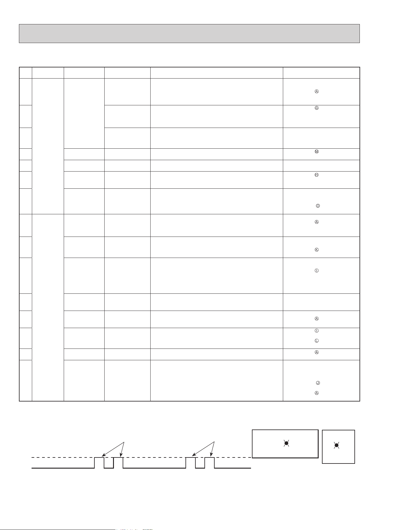
46
10-3. TROUBLESHOOTING CHECK TABLE
No. Symptom LED indication
Abnormal point/
Condition
Condition Remedy
1
Outdoor unit
does not op-
erate.
1-time blink every
2.5 seconds
Outdoor power sys-
tem
Overcurrent protection cut-out operates 3 consecutive times
within 1 minute after the compressor gets started.
•
Reconnect connector of compres-
sor.
•
Refer to 10-5.
"How to check
inverter/compressor".
•
Check stop valve.
2
Outdoor thermistors Discharge temperature thermistor, n temperature thermistor,
defrost thermistor, P.C. board temperature thermistor, outdoor
heat exchanger temperature thermistor or ambient tempera-
ture thermistor shorts or opens during compressor running.
•
Refer to 10-5.
"Check of outdoor
thermistors".
3
Outdoor control sys-
tem
Nonvolatile memory data cannot be read properly.
(The upper lamp of the OPERATION INDICATOR lamp on the
indoor unit lights up or blinks 7-time.)
•
Replace inverter P.C. board.
4
6-time blink
2.5 seconds OFF
Serial signal The communication fails between the indoor and outdoor unit
for 3 minutes.
•
Refer to 10-5.
"How to check
miswiring and serial signal error.
5
11-time blink
2.5 seconds OFF
Stop valve/
Closed valve
Closed valve is detected by compressor current.
•
Check stop valve.
6
16-time blink
2.5 seconds OFF
4-way valve/
Pipe temperature
The 4-way valve does not work properly.
The indoor coil thermistor detects an abnormal temperature.
•
Refer to 10-5.
"Check of R.V.
coil".
•
Replace the inverter P.C. board.
7
17-time blink
2.5 seconds OFF
Outdoor refrigerant
system abnormality
A closed valve and air trapped in the refrigerant circuit are
detected based on the temperature sensed by the indoor and
outdoor thermistors and the current of the compressor.
•
Check for a gas leak in a
connecting piping etc.
•
Check the stop valve.
•
Refer to 10-5.
“Check of outdoor
refrigerant circuit”.
8
'Outdoor unit
stops and
restarts 3
minutes later'
is repeated.
2-time blink
2.5 seconds OFF
Overcurrent protec-
tion
Large current ows into the power module (IC700) (MUZ-
GL09/12/15/18, MUY-
GL09/12/15/18
)/ IGBT module (IC700)
(MUZ-GL24, MUY-GL24).
•
Reconnect connector of compressor.
•
Refer to 10-5.
"How to check
inverter/compressor".
•
Check stop valve.
9
3-time blink
2.5 seconds OFF
Discharge tem-
perature overheat
protection
Temperature of discharge temperature thermistor exceeds
241°F (116°C), compressor stops. Compressor can restart if
discharge temperature thermistor reads 212°F (100°C) or less
3 minutes later.
•
Check refrigerant circuit and refrig-
erant amount.
•
Refer to 10-5.
"Check of LEV".
10
4-time blink
2.5 seconds OFF
Fin temperature
/P.C. board tem-
perature thermistor
overheat protection
Temperature of the n temperature thermistor on the heat sink
exceeds 167 - 187°F (75 - 86°C) (MUZ-GL09/12/15/18, MUY-
GL09/12/15/18)/167 - 176°F (75 - 80°C) (MUZ-GL24, MUY-
GL24) or temperature of P.C. board temperature thermistor on
the inverter P.C.board exceeds 162 - 185°F (72 - 85°C) (MUZ-
GL09/12/15/18, MUY-GL09/12/15/18)/158 - 167°F (70 - 75°C)
(MUZ-GL24, MUY-GL24).
•
Check around outdoor unit.
•
Check outdoor unit air passage.
•
Refer to 10-5.
"Check of outdoor
fan motor".
11
5-time blink
2.5 seconds OFF
High pressure pro-
tection
Indoor coil thermistor exceeds 158°F (70°C) in HEAT mode.
Defrost thermistor exceeds 158°F (70°C) in COOL mode.
•
Check refrigerant circuit and refrig-
erant amount.
•
Check stop valve.
12
8-time blink
2.5 seconds OFF
Compressor syn-
chronous abnormal-
ity
The waveform of compressor current is distorted.
•
Reconnect connector of compressor.
•
Refer to 10-5.
"How to check
inverter/compressor".
13
10-time blink
2.5 seconds OFF
Outdoor fan motor Outdoor fan has stopped 3 times in a row within 30 seconds
after outdoor fan startup.
•
Refer to 10-5.
"Check of outdoor
fan motor.
•
Refer to 10-5.
"Check of inverter
P.C. board.
14
12-time blink
2.5 seconds OFF
Each phase current
of compressor
Each phase current of compressor cannot be detected nor-
mally.
•
Refer to 10-5.
"How to check
inverter/compressor".
15
13-time blink
2.5 seconds OFF
Bus-bar voltage (DC) Bus-bar voltage of inverter cannot be detected normally.
•
It occurs with following case.
Instantaneous power voltage drop.
(Short time power failure) (MUZ-
GL24, MUY-GL24)
•
Refer to 10-5.
"Check of power
supply". (MUZ-GL24, MUY-GL24)
•
Refer to 10-5.
"How to check in-
verter/compressor".
NOTE: 1. The location of LED is illustrated at the right gure. Refer to 10-6.1.
2. LED is lit during normal operation.
3. Blinking patterns of this mode dier from the ones of the failure recall mode.
The blinking frequency shows the number of times the LED blinks after every 2.5-second OFF.
(Example) When the blinking frequency is “2”.
ON
OFF
2.5-second OFF
2.5-second OFF
0.5-second ON
0.5-second ON
LED
Blinking →
MUZ-GL09/12/15/18NA
MUZ-GL09/12/15/18NAH
MUY-GL09/12/15/18NA
Inverter P.C. board
MUZ-GL24NA
MUZ-GL24NAH
MUY-GL24NA
LED
→
Blinking
OBH733J
47
ON
OFF
2.5-second OFF
2.5-second OFF
0.5-second ON
0.5-second ON
LED
Blinking →
MUZ-GL09/12/15/18NA
MUZ-GL09/12/15/18NAH
MUY-GL09/12/15/18NA
Inverter P.C. board
MUZ-GL24NA
MUZ-GL24NAH
MUY-GL24NA
LED
→
Blinking
No. Symptom LED indication
Abnormal point/
Condition
Condition Remedy
16
Outdoor unit
operates.
1-time blink
2.5 seconds OFF
Frequency drop by
current protection
MUZ-
GL09/12/15/18
MUY-
GL09/12/15/18
When the input current exceeds ap-
proximately 10.5A, compressor fre-
quency lowers.
The unit is normal, but check the
following.
•
Check if indoor lters are clogged.
•
Check if refrigerant is short.
•
Check if indoor/outdoor unit air
circulation is short cycled.
MUZ-GL24
MUY-GL24
Current from power outlet is nearing
breaker capacity.
17
3-time blink
2.5 seconds OFF
Frequency drop by
high pressure pro-
tection
Temperature of indoor coil thermistor exceeds 131 °F (55°C)
in HEAT mode, compressor frequency lowers.
Frequency drop by
defrosting in COOL
mode
Indoor coil thermistor reads 46°F (8°C) or less in COOL mode,
compressor frequency lowers.
18
4-time blink
2.5 seconds OFF
Frequency drop by
discharge tempera-
ture protection
Temperature of discharge temperature thermistor exceeds
232°F (111°C), compressor frequency lowers.
•
Check refrigerant circuit and refrig-
erant amount.
•
Refer to 10-5.
"Check of LEV".
•
Refer to 10-5.
"Check of outdoor
thermistors".
19
5-time blink
2.5 seconds OFF
Outside temperature
thermistor protec-
tion
When the outside temperature thermistor shorts or opens,
protective operation without that thermistors is performed.
•
Refer to 10-5.
Check of outdoor
thermistors.
20
7-time blink
2.5 seconds OFF
Low discharge tem-
perature protection
Temperature of discharge temperature thermistor has been
122°F (50°C) or less for 20 minutes.
•
Refer to 10-5.
"Check of LEV".
•
Check refrigerant circuit and refrig-
erant amount.
21
8-time blink
2.5 seconds OFF
MUZ-GL09/12/15/18
MUY-GL09/12/15/18
PAM protection
PAM: Pulse Ampli-
tude Modulation
The overcurrent ows into PFC (Power factor correction
:IC820) or the Bus-bar voltage reaches 394 V or more, PAM
stops and restarts.
This is not malfunction. PAM pro-
tection will be activated in the fol-
lowing cases:
1 Instantaneous power voltage
drop. (Short time power failure)
2 When the power supply voltage
is high.
MUZ-GL24
MUY-GL24
Zero cross detecting
circuit
Zero cross signal cannot be detected.
•
It occurs with following cases.
1 Instantaneous power voltage
drop. (Short time power failure)
2 Distortion of primary voltage
•
Refer to 10-5.
"Check of power
supply".
22
9-time blink
2.5 seconds OFF
Inverter check mode The connector of compressor is disconnected, inverter check
mode starts.
•
Check if the connector of the com-
pressor is correctly connected.
Refer to 10-5.
"How to check
inverter/compressor".
NOTE: 1. The location of LED is illustrated at the right gure. Refer to 10-6.1.
2. LED is lit during normal operation.
3. Blinking patterns of this mode dier from the ones of the failure recall mode.
The blinking frequency shows the number of times the LED blinks after every 2.5-second OFF.
(Example) When the blinking frequency is “2”.
OBH733J
48
10-4. TROUBLESHOOTING CRITERION OF MAIN PARTS
MUZ-GL09NA MUZ-GL09NAH MUY-GL09NA
MUZ-GL12NA MUZ-GL12NAH MUY-GL12NA
MUZ-GL15NA MUZ-GL15NAH MUY-GL15NA
MUZ-GL18NA MUZ-GL18NAH MUY-GL18NA
MUZ-GL24NA MUZ-GL24NAH MUY-GL24NA
Part name Check method and criterion Figure
Defrost thermistor (RT61)
(MUZ)
Fin temperature
thermistor (RT64)
Ambient temperature ther-
mistor (RT65)
Outdoor heat exchanger tem-
perature thermistor (RT68)
Measure the resistance with a tester.
Refer to 10-6. “Test point diagram and voltage”, 1. “Inverter P.C. board”,
for the chart of thermistor.
Discharge temperature ther-
mistor (RT62)
Measure the resistance with a tester. Before measurement, hold the
thermistor with your hands to warm it up.
Refer to 10-6. “Test point diagram and voltage”, 1. “Inverter P.C. board”,
for the chart of thermistor.
Compressor
Measure the resistance between terminals using a tester.
[Temperature: 14 - 104°F (-10 - 40°C)]
Normal (Ω)
MUZ-GL09NA-
U1
MUZ-GL09NAH-
U1
MUY-GL09NA-
U1
MUZ-GL09NA-
U2
MUZ-GL09NAH-
U2
MUY-GL09NA-
U2
MUZ-GL09NA-
U8
MUZ-GL09NAH-
U8
MUZ-GL12
MUY-GL12
MUZ-
GL15/18
MUY-
GL15/18
MUZ-GL24
MUY-GL24
U-V
U-W
V-W
1.26 - 1.72 1.59 - 2.16 1.60 - 2.17 0.82 - 1.11 0.87 - 1.18
W
U
V
WHT
RED BLK
Outdoor fan motor
Measure the resistance between lead wires using a tester.
[Temperature: 14 - 104°F (-10 - 40°C)]
Color of lead wire
Normal (Ω)
MUZ-GL09/12/15-
U1
MUY-GL09/12/15-
U1
MUZ-GL09NA-
U8
MUZ-GL09/12/15-
U2
MUY-GL09/12/15-
U2
MUZ-GL18/24
MUY-GL18/24
RED – BLK
BLK – WHT
WHT – RED
29 - 40 28 - 39 12 - 16
W
U
V
WHT
RED BLK
R. V. coil (21S4)
Measure the resistance using a tester.
[Temperature: 14 - 104°F (-10 - 40°C)]
Normal (kΩ)
MUZ-GL09/12NA-
U1
,
U8
MUZ-GL09/12NAH-
U1
,
U8
MUZ-GL15/18/24NA, MUZ-GL15/18/24NAH
MUZ-GL09/12NA-
U2
MUZ-GL09/12NAH-
U2
0.97 - 1.38 1.65 - 2.48
Expansion valve coil (LEV)
Measure the resistance using a tester.
[Temperature: 14 - 104°F (-10 - 40°C)]
Color of lead wire Normal (Ω)
RED – ORN
37 - 54
RED – WHT
RED – BLU
RED – YLW
RED
(+12V)
YLW
BLU
WHT
ORN
LEV
Defrost heater
(MUZ-GL·NAH)
Measure the resistance using a tester.
[Temperature: 14 - 104°F (-10 - 40°C)]
Normal (Ω)
GL09/12/15 GL18/24
349 - 428 376 - 461
OBH733J
49
10-5. TROUBLESHOOTING FLOW
Are the voltages balanced?
Disconnect the connector between the compressor
and the power module (IC700) (MUZ-GL09/12/15/18,
MUY-GL09/12/15/18)/IGBT module (IC700) (MUZ-
GL24, MUY-GL24).
Replace the inverter P.C. board.
Check the voltage between terminals.
Check the compressor.
See 10-5. “Check of compressor”.
No
Yes
See 10-5. “Check of open phase”.
A How to check inverter/compressor
Refer to 10-5. “Check of compressor
operation time”.
Does the compressor operate continuously?
Refer to 10-5.
“Check of compressor start failure”.
OK
No
Yes
Refer to 10-5. “Check of compressor
winding”.
Is the compressor normal?
Replace the compressor.
No
Yes
B Check of open phase
C Check of compressor
● With the connector between the compressor and the power module (IC700) (MUZ-GL09/
12/15/
18, MUY-GL
09/12/15/
18)/IGBT
module (IC700) (MUZ-GL24, MUY-GL24) disconnected, activate the inverter and check if the inverter is normal by measuring
the voltage balance between the terminals.
Output voltage is 50 - 130 V. (The voltage may dier according to the tester.)
<< Operation method>>
Start cooling or heating operation by pressing EMERGENCY OPERATION switch on the indoor unit. (TEST RUN OPERA-
TION: Refer to 7-6.)
<<Measurement point>>
At 3 points
BLK (U)-WHT (V)
BLK (U)-RED (W)
WHT(V)-RED (W)
NOTE: 1. Output voltage varies according to power supply voltage.
2. Measure the voltage by analog type tester.
3. During this check, LED of the inverter P.C. board blinks 9 times. (Refer to 10-6.1.)
*Measure AC voltage between the lead wires at 3 points.
OBH733J
50
F Check of compressor start failure
D Check of compressor winding
E Check of compressor operation time
●Disconnect the connector between the compressor and the power module (IC700) (MUZ-GL09/12/15/18, MUY-GL09/12/15/18)/
IGBT module (IC700) (MUZ-GL24, MUY-GL24), and measure the resistance between the compressor terminals.
<<Measurement point>>
At 3 points
BLK-WHT
BLK-RED
WHT-RED
<<Judgement>>
Refer to 10-4.
0 [Ω] ················Abnormal [short]
Infinite [Ω] ·······Abnormal [open]
NOTE: Be sure to zero the ohmmeter before measurement.
*Measure the resistance between the lead wires at 3 points.
After the compressor is heated with a drier,
does the compressor start? *1
Replace the compressor.
Compressor start failure. Activate pre-heat control.
(Refer to 9-2. "PRE-HEAT CONTROL SETTING")
No
Yes
Does the compressor run for 10 seconds or
more after it starts?
Check the refrigerant circuit.
Check the stop valve.
Yes
No
*1
Heat the compressor with
a drier for about 20 minutes.
Do not recover refrigerant
gas while heating.
Heating part
● Connect the compressor and activate the inverter. Then measure
the time until the inverter stops due to overcurrent.
<<Operation method>>
Start heating or cooling operation by pressing EMERGENCY
OPERATION switch on the indoor unit. (TEST RUN OPERATION:
Refer to 7-6.)
<<Measurement>>
Measure the time from the start of compressor to the stop of
compressor due to overcurrent.
Compressor starts
Abnormal
(IC700 failure)
(Compressor winding short)
Abnormal
(Compressor lock out)
(Starting defect)
Abnormal
(Poor contact)
(Inverter P.C. board defect)
(Disconnected connector)
Abnormal
(Refrigerant circuit defect)
(Closed valve)
Normal
0 second
1 second
2 seconds
10 seconds
10 minutes
<<Judgement>>
Conrm that ~ is normal.
•Electrical circuit check
. Contact of the compressor connector
. Output voltage of inverter P.C. board and balance of them (See 10-5. )
. Direct current voltage between DB61(+) and (-) (MUZ-GL09/12/15/18,
MUY-GL09/12/15/18)/ JP715(+) and JP30(-) (MUZ-GL24, MUY-GL24), on
the inverter P.C. board
. Voltage between outdoor terminal block S1-S2
OBH733J
51
G Check of outdoor thermistors
Replace the thermistor except RT64.
When RT64 is abnormal, replace the inverter P.C.
board.
Replace the inverter P.C. board.
No
No
Is the resistance of thermistor normal?
(Refer to 10-6.1.)
Reconnect the connector of thermistor.
Turn ON the power supply and press EMERGENCY OPERATION switch.
Does the unit operate for 10 minutes or more
without showing thermistor abnormality?
OK
(Cause is poor contact.)
Yes
Yes
Disconnect the connector of thermistor in the inverter P.C. board (see
below table), and measure the resistance of thermistor.
MUZ-GL09/12/15/18, MUY-GL09/12/15/18
Thermistor Symbol Connector, Pin No. Board
Defrost (MUZ) RT61 Between CN641 pin1 and pin2
Inverter P.C. board
Discharge temperature RT62 Between CN641 pin3 and pin4
Fin temperature RT64 Between CN642 pin1 and pin2
Ambient temperature RT65 Between CN643 pin1 and pin2
Outdoor heat exchanger temperature RT68 Between CN644 pin1 and pin3
MUZ-GL24, MUY-GL24
Thermistor Symbol Connector, Pin No. Board
Defrost (MUZ) RT61 Between CN671 pin1 and pin2
Inverter P.C. board
Discharge temperature RT62 Between CN671 pin3 and pin4
Fin temperature RT64 Between CN673 pin1 and pin2
Ambient temperature RT65 Between CN672 pin1 and pin2
Outdoor heat exchanger temperature RT68 Between CN671 pin5 and pin6
OBH733J
52
H Check of R.V. coil
MUZ-GL09/12/15/18NA MUZ-GL09/12/15/18NAH
(MUZ)
MUZ-GL24NA MUZ-GL24NAH
* First of all, measure the resistance of R.V. coil to check if the coil is defective. Refer to 10-4.
* In case CN721 is disconnected or R.V. coil is open, voltage is generated between the terminal pins of the connector
although no signal is being transmitted to R.V. coil.
Check if CN721 is connected.
Is there 208/230 V AC between CN721
and
on the inverter P.C. board
3 minutes after the power supply is turned
ON?
No
Yes
Replace the inverter
P.C. board.
Replace the 4-way valve.
Unit operates in COOL mode even if it is set to HEAT mode.
Is there 208/230 V AC between CN721
and
on the inverter P.C. board
3 minutes after the power supply is turned
ON?
Yes
No
Replace the inverter
P.C. board.
Replace the 4-way valve.
Unit operates in HEAT mode even if it is set to COOL mode.
Disconnect connector between the
compressor and the power module
(IC700).
Turn ON the power supply and press
EMERGENCY OPERATION switch
twice (HEAT mode).
Disconnect connector between the
compressor and the power module
(IC700).
Turn ON the power supply and
press EMERGENCY OPERATION
switch once (COOL mode).
* First of all, measure the resistance of R.V. coil to check if the coil is defective. Refer to 10-4.
* In case CN602 is disconnected or R.V. coil is open, voltage is generated between the terminal pins of the connector
although no signal is being transmitted to R.V. coil.
Check if CN602 is connected.
Is there 208/230 V AC between CN602
and
on the inverter P.C. board
3 minutes after the power supply is turned
ON?
No
Yes
Replace the inverter
P.C. board.
Replace the 4-way valve.
Unit operates in COOL mode even if it is set to HEAT mode.
Is there 208/230 V AC between CN602
and
on the inverter P.C. board
3 minutes after the power supply is turned
ON?
Yes
No
Replace the inverter
P.C. board.
Replace the 4-way valve.
Unit operates in HEAT mode even if it is set to COOL mode.
Disconnect connector between the
compressor and the IGBT module
(IC700).
Turn ON the power supply and press
EMERGENCY OPERATION switch
twice (HEAT mode).
Disconnect connector between the
compressor and the IGBT module
(IC700).
Turn ON the power supply and
press EMERGENCY OPERATION
switch once (COOL mode).
OBH733J
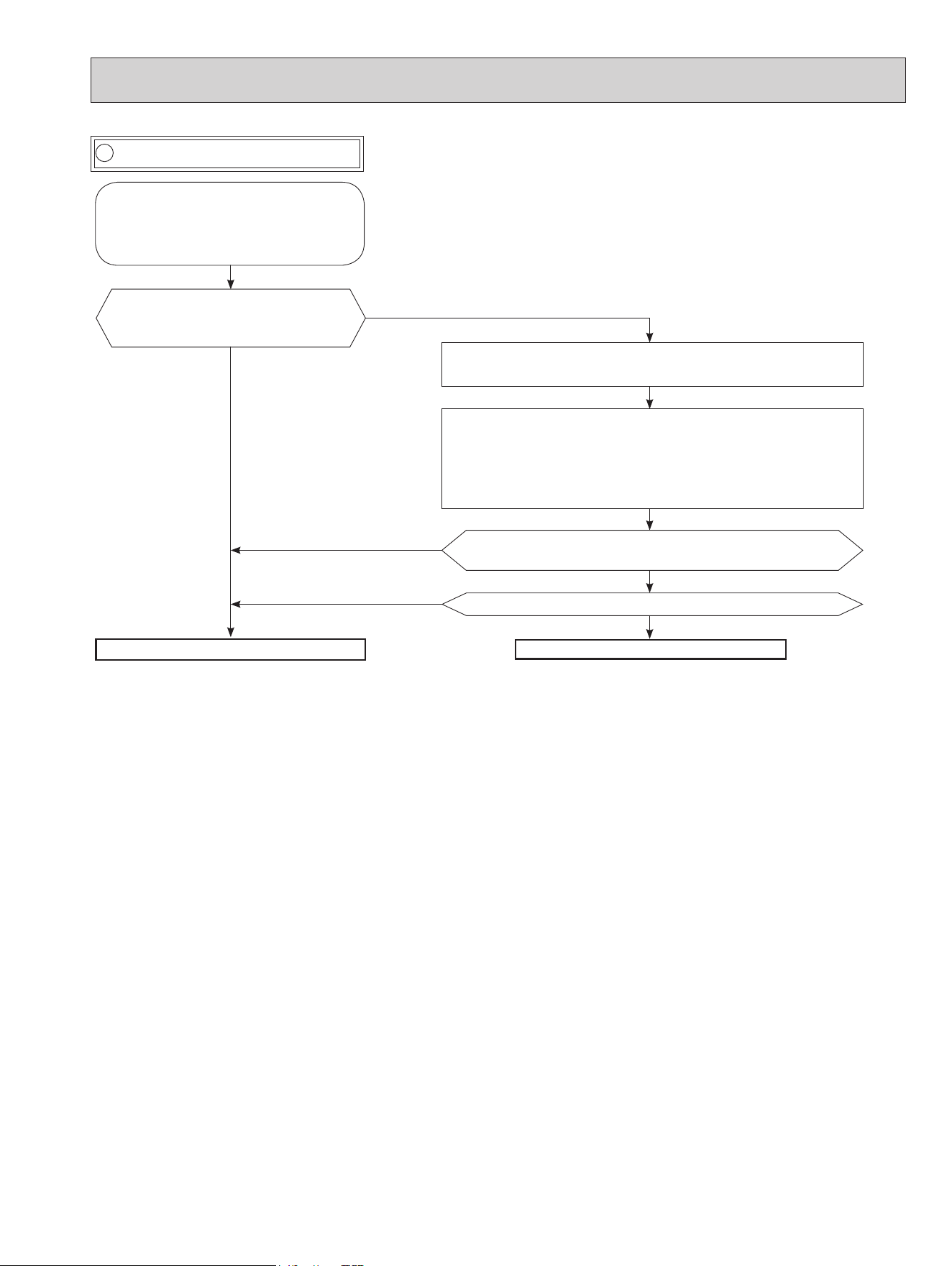
53
I Check of outdoor fan motor
Is the resistance between each ter-
minal of outdoor fan motor normal?
(Refer to 10-4.)
Disconnect CN932 from the inverter P.C. board, and turn on the
power supply.
Rotate the outdoor fan motor manually and measure the voltage
of CN931.
Between 1(+) and 5(-)
Between 2(+) and 5(-)
Between 3(+) and 5(-)
Does the voltage between each terminal become 5 and 0 V
DC repeatedly?
Does the outdoor fan motor rotate smoothly?
Replace the outdoor fan motor.
Replace the inverter P.C. board.
Yes
Yes
No
(Fixed to either 5 or 0 V DC)
No
No
Yes
Check the connection between the
connector CN931 and CN932.
Disconnect the connectors CN931
and CN932 from the inverter P.C.
board.
OBH733J
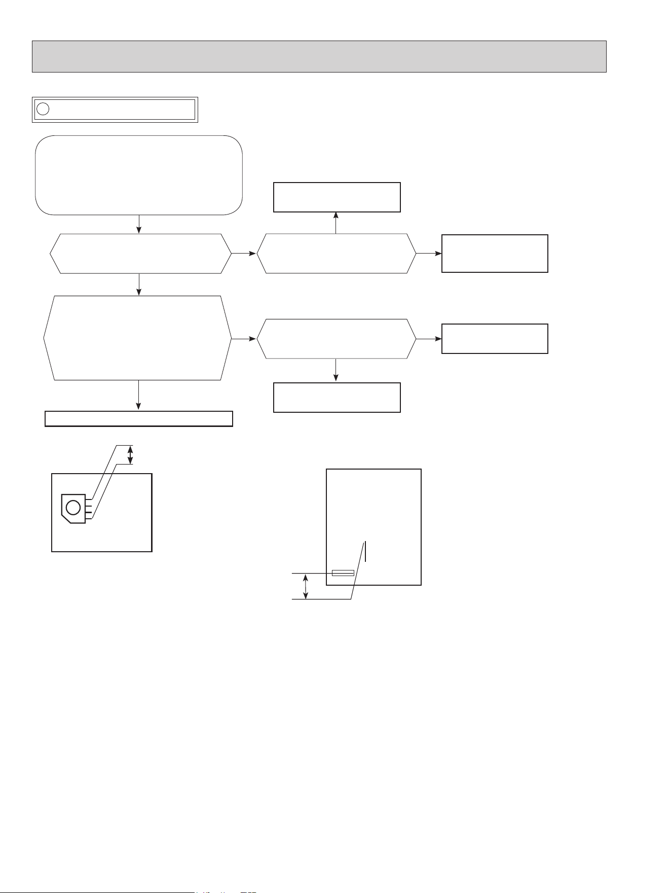
54
J Check of power supply
Is there voltage 208/230 V AC
between the indoor terminal
block S1 and S2?
Yes
No
Replace the indoor
electronic control P.C.
board.
Rectify indoor/outdoor
connecting wire.
Yes
If lights up, OK.
If blinks, refer to 10-3.
Does the upper lamp of the
OPERATION INDICATOR lamp on
the indoor unit light up?
Does LED on the inverter P.C.
board light up or blink?
(Refer to 10-6.1.)
No
Replace the inverter
P.C. board.
Is there Bus-bar voltage 260 - 370 V
DC between DB61 (+) and DB61 (–)
(MUZ-GL09/12/15/18, MUY-
GL09/12/15/18)/294 - 370 V DC
between JP715 (+) and JP30 (–)
(MUZ-GL24, MUY-GL24) on the
inverter P.C. board? (Refer to 10-6.1.)
No
Check the electric parts in main circuit.
Yes
Yes
No
Disconnect the connector between the
compressor and the power module
(IC700) (MUZ-GL09/12/15/18, MUY-
GL09/12/15/18)/IGBT module (IC700)
(MUZ-GL24, MUY-GL24).
Turn ON power supply and press
EMERGENCY OPERATION switch.
294 -370 V DC
JP30
JP715
MUZ-GL09/12/15/18NA
MUZ-GL09/12/15/18NAH
MUY-GL09/12/15/18NA
MUZ-GL24NA
MUZ-GL24NAH
MUY-GL24NA
Inverter P.C. board
(Solder side)
DB61
260 - 370 V DC
OBH733J
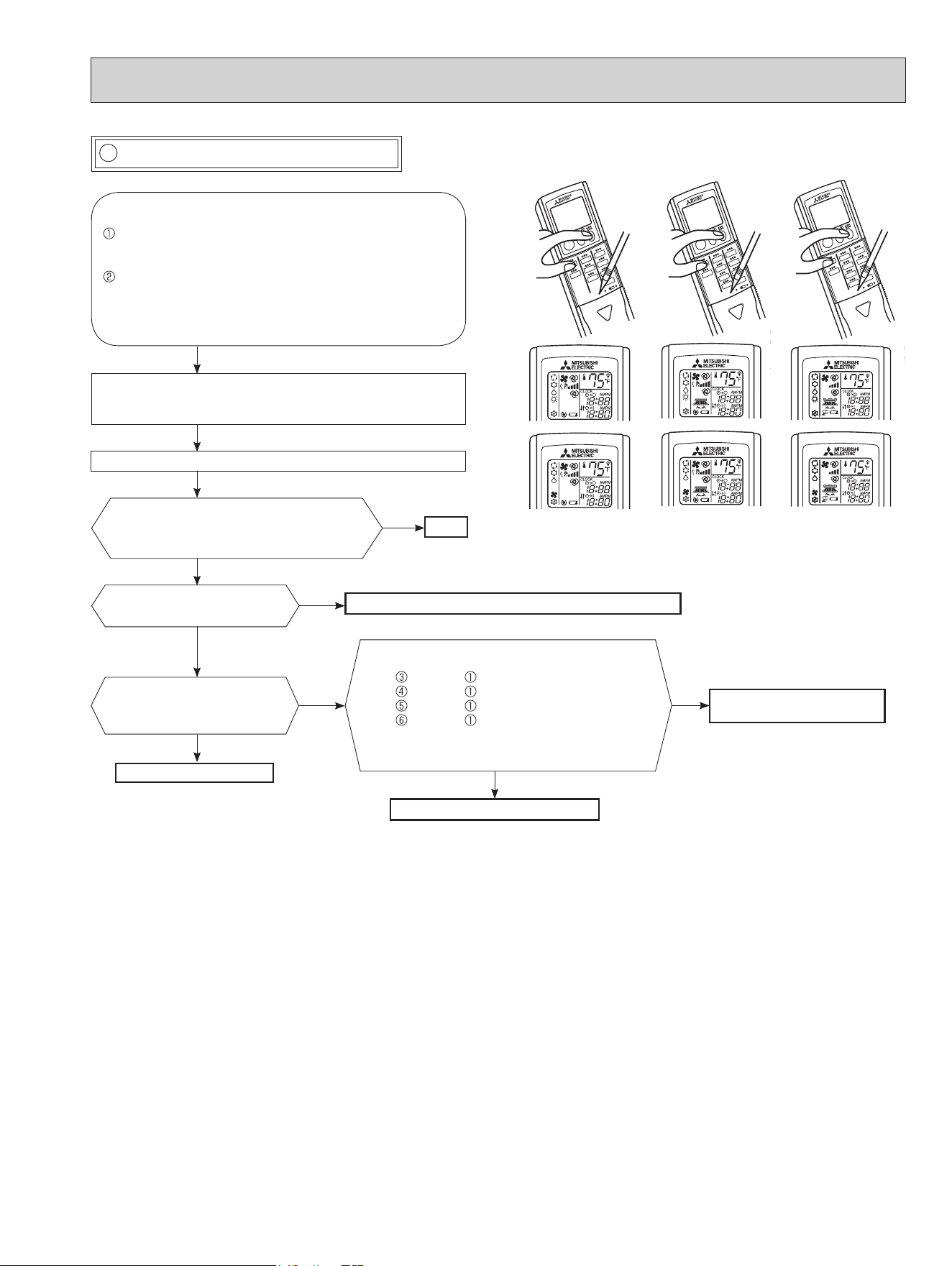
55
Press STOP/OPERATE (OFF/ON) button of the remote
controller (the set temperature is displayed) with the
remote controller headed towards the indoor unit. *1
Expansion valve operates in full-opening direction.
OK
NOTE: After check of LEV, take the following steps.
1. Turn OFF the power supply and turn it ON again.
2. Press RESET button on the remote controller.
*1. Regardless of normal or abnormal condition, a short beep is
emitted once the signal is received.
Measure each voltage between connector
pins of CN724 on the inverter P.C. board.
1. Pin (-) — Pin (+)
2. Pin (-) — Pin (+)
3. Pin (-) — Pin (+)
4. Pin (-) — Pin (+)
Is there about 3 - 5 V AC between each?
NOTE: Measure the voltage by an analog
tester.
Properly x the LEV coil to the expansion valve.
Replace the inverter P.C.
board.
Replace the LEV coil.
Replace the expansion valve.
Is LEV coil properly xed to
the expansion valve?
Does the resistance of LEV
coil have the characteristics?
(Refer to 10-4.)
Do you hear the expansion valve "click,
click·······"?
Do you feel the expansion valve vibrates
when touching it ?
Turn ON the power supply.
<Preparation of the remote controller>
While pressing both OPERATION SELECT button
and TOO COOL button on the remote controller at the
same time, press RESET button.
First, release RESET button.
Hold down the other 2 buttons for another 3 seconds.
Make sure that the indicators on the LCD screen
shown in the right gure are all displayed. Then re-
lease the buttons.
Yes
No
No
Yes
No
Yes
No
Yes
K Check of LEV (Expansion valve)
MSZ-GL18NA
MSY-GL18NA
MSZ-GL24NA
MSY-GL24NA
MSZ-GL06/09/12/15NA
MSY-GL09/12/15NA
MSZ type
MSY type
OBH733J
56
Check the outdoor fan motor.
(Refer to 10-5.
.)
Is the fuse (F901) blown on the in-
verter P.C. board?
Check the connection of the connectors
(CN931, CN932) of the outdoor fan motor.
If the connection is poor, make it correct.
Operate the outdoor unit by starting
EMERGENCY OPERATION.
Check the LED indication on the in-
verter P.C. board.
Does the LED blink 10 times?
Replace the inverter P.C. board.
Check the corresponding parts
following LED indication.
(Refer to 10-3.)
Yes
No
Yes
(10-time blink)
No
L Check of inverter P.C. board
OBH733J
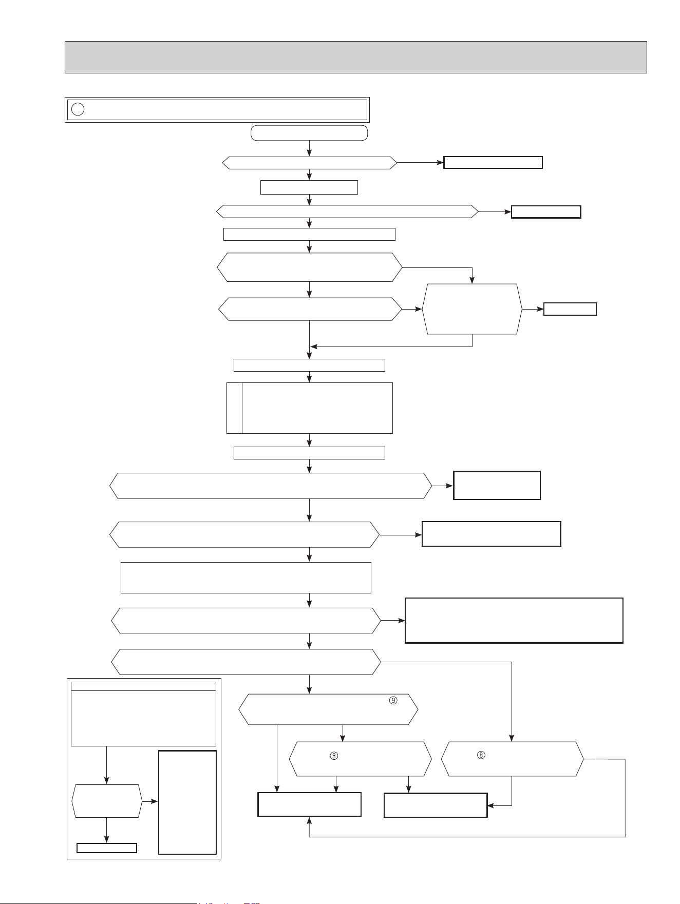
57
M How to check miswiring and serial signal error
• Turn OFF inverter-controlled lighting
equipment.
• Turn OFF the power supply and then
turn ON again.
• Press EMERGENCY OPERATION
switch.
A
Is serial signal
error indicated 6
minutes later?
B
Yes
• Reinstall
either the unit
or the light
away from
each other.
• Attach a lter
on remote
control receiv-
ing section
of the indoor
unit.
No
Turn OFF the power supply.
Is there rated voltage in the power supply?
Yes
No
Turn ON the power supply.
Check the power supply.
Is there rated voltage between the outdoor terminal block S1 and S2?
No
Check the wiring.
Press EMERGENCY OPERATION switch once.
Does the left lamp of OPERATION INDICATOR
lamp light up? <Conrmation of the power to
the indoor unit>
Yes
No
Is serial signal error indicated 6 minutes later?
Yes
No
Is there any miswiring,
poor contact, or wire
disconnection of the
indoor/outdoor connect-
ing wire?
Yes
Correct them.
No
A
Turn OFF the power supply.
Check once more if the indoor/outdoor
connecting wire is not miswiring.
Bridge the outdoor terminal block S2 and
S3. *1
B
*
1. Miswiring may damage indoor electronic control P.C.
board during the operation.
Be sure to conrm the wiring is correct before the opera-
tion starts.
Turn ON the power supply.
Does the LED on the inverter P.C. board repeat
"3.6-second-OFF and 0.8-second-ON quick blinking"? *3
Yes
No
(Lit or
not lit)
Replace the inverter P.C. board . *2
*
2. Be careful of the residual voltage of smoothing
capacitor.
Is there amplitude of 10 to 20 V DC between the indoor terminal block
S2 and S3? <Conrmation of serial signal>
Yes
Check the wiring
If there are any error of the indoor/outdoor connecting wire:
such as the damage of the wire, intermediate connection,
and/or poor contact to the terminal block, replace the indoor/
outdoor connecting wire.
No
Is there 2 V DC or less between CN202 (+)
and JPG (GND)(-) on the indoor electronic
control P.C. board?
No
Yes
Yes
*
3. Be sure to check this within 3 minutes after turning ON.
After 3 minutes, LED blinks 6 times. Even when the
inverter P.C. board is normal, LED blinks 6 times after 3
minutes.
Is there 2 V DC or less between
CN202 (+) and JPG (GND)(-) on
the indoor electronic control P.C.
board?
Is there 2 V DC or less between
CN202A
(+) and JPG (GND)(-)
on the indoor electronic control P.C.
board?
Replace the indoor elec-
tronic control P.C. board.
No Ye s No
Yes
Is the bus-bar voltage of the inverter P.C. board normal?
(Refer to "TEST POINT DIAGRAM AND VOLTAGE" in the outdoor service manual.)
No
Yes
Check of power supply.
Turn OFF the power supply.
Remove the bridge between the outdoor terminal block S2 and S3.
Turn ON the power supply.
Yes
No
Replace the indoor power
P.C. board.
Is there rated voltage between the indoor terminal block S1 and S2?
<Conrmation of power voltage>
MUZ-GL09/12/15NA
MUZ-GL09/12/15NAH
MUY-GL09/12/15NA
OBH733J
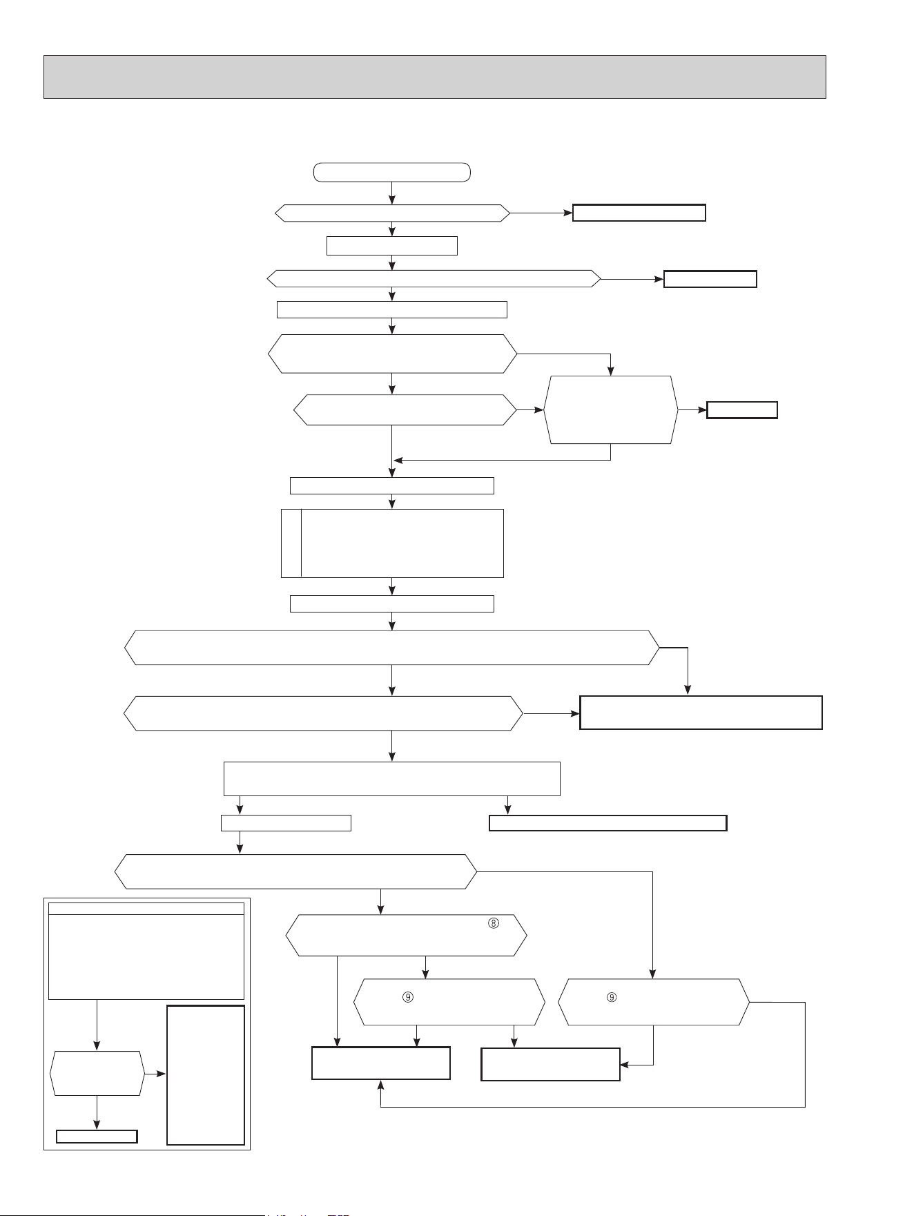
58
• Turn OFF inverter-controlled lighting
equipment.
• Turn OFF the power supply and then
turn ON again.
• Press EMERGENCY OPERATION
switch.
A
Is serial signal
error indicated 6
minutes later?
B
Yes
• Reinstall
either the unit
or the light
away from
each other.
• Attach a lter
on remote
control receiv-
ing section
of the indoor
unit.
No
Turn OFF the power supply.
Is there rated voltage in the power supply?
Yes
No
Turn ON the power supply.
Check the power supply.
Is there rated voltage between outdoor terminal block S1 and S2?
No
Check the wiring.
Press EMERGENCY OPERATION switch once.
Does the OPERATION INDICATOR lamp light
up? <Conrmation of the power to the indoor
unit>
Yes
No
Is serial signal error indicated 6 minutes
later?
Yes
No
Is there any miswiring,
poor contact, or wire
disconnection of the
indoor/outdoor connect-
ing wire?
Yes
Correct them.
No
A
Turn OFF the power supply.
Check once more if the indoor/outdoor
connecting wire is not miswiring.
Bridge the outdoor terminal block S2 and
S3. *1
B
*1. Miswiring may damage indoor electronic control P.C.
board during the operation.
Be sure to conrm the wiring is correct before the opera-
tion starts.
Turn ON the power supply.
Does the LED on the inverter P.C. board or the outdoor electronic control P.C.
board repeat "3.6-second-OFF and 0.8-second-ON quick blinking"? *3
Yes
GL24GL18
No
(Lit or
not lit)
Replace the inverter P.C. board or the outdoor
electronic control P.C. board. *2
*
2. Be careful of the residual voltage of smoothing
capacitor.
Turn OFF the power supply.
Remove the bridge between outdoor terminal block S2 and S3.
Yes
*3. Be sure to check this within 3 minutes after turning ON.
After 3 minutes, LED blinks 6 times. Even when the
inverter P.C. board or the outdoor electronic control P.C.
board is normal, LED blinks 6 times after 3 minutes.
(Except for outdoor unit of multi system type)
Is the bus-bar voltage of the inverter P.C. board or the outdoor electronic control P.C. board normal? (Refer
to "TEST POINT DIAGRAM AND VOLTAGE" in the outdoor service manual.)
No
Yes
Replace the indoor electronic control P.C. board.Turn on the power supply.
Is there amplitude of 10 to 20 V DC between the indoor terminal block
S2 and S3? <Conrmation of serial signal>
Yes
Is there 2 V DC or less between CN10A (+)
and GND (-) on the indoor electronic control
P.C. board?
No
Yes
Is there 2 V DC or less between
CN10A (+) and GND (-) on
the indoor electronic control P.C.
board?
Is there 2 V DC or less between
CN10A
(+) and GND (-) on
the indoor electronic control P.C.
board?
Replace the indoor elec-
tronic control P.C. board.
No Ye s No
Yes
No
Replace the indoor power
P.C. board.
MUZ-GL18/24NA
MUZ-GL18/24NAH
MUY-GL18/24NA
OBH733J
59
O Check of outdoor refrigerant circuit
N Check of defrost heater (base pan heater)
MUZ-GL09/12/15/18/24NAH
(MUZ-GL•NAH)
Check the following points before checking electric continuity.
1. Does the resistance of ambient temperature thermistor have the characteristics? Refer to 10-6.1.
2. Is the resistance of defrost heater normal? Refer to 10-4.
3. Does the heater protector remain conducted (not open)?
4. Are both ambient temperature thermistor and circuit of defrost heater securely connected to connectors?
Is there 208/230 V AC between CN601 and
(MUZ-GL24NAH)/CN722 and (Other models)
on the inverter P.C. board? Refer to 10-6.1.
Not the problem of the inverter P.C. board.
Replace the inverter P.C. board.
No
Yes
In HEAT mode, for more than 5 minutes, let the ambient temperature thermistor continue to read
32°F (0°C) or below, and let the defrost thermistor continue to read 30°F (-1°C) or below.
NOTE: In case both thermistors are more than the above temperature, cool them with cold
water etc...
Has the operation stopped during pump down?
Was the operation started with the stop valve
closed, and was it opened during operation?
No
Yes
The operation has stopped to prevent the diesel explosion
caused by air trapped in the refrigerant circuit. Close the stop
valve, and disconnect the power plug or turn the breaker OFF.
The unit occasionally stops when the stop valve is opened
or closed during operation. Open the stop valve and start the
cooling operation again.
Yes
No
The refrigerant gas amount may be 60% or less than
the normal amount. Identify where the gas is leaking
from, and x the leak.
CAUTION :
Do not start the operation again to prevent hazards.
OBH733J
60
P Electromagnetic noise enters into TV sets or radios
Is the unit grounded?
Ground the unit.
Is the distance between the antennas
and the indoor unit within 9.91 ft.
(3m)
,
or is the distance between the antennas
and the outdoor unit within 9.91 ft.
(3m)
?
Extend the distance between the antennas and
the indoor unit, and/or the antennas and the
outdoor unit.
Is the distance between the TV sets or ra-
dios and the indoor unit within 3.28 ft.
(1m)
,
or is the distance between the TV sets or
radios and the outdoor unit within
9.91 ft.
(3m)
?
Extend the distance between the TV sets and/or
radios and the indoor unit, or the TV sets or
radios and the outdoor unit.
Are the antennas damaged?
Is the coaxial cable damaged?
Is there any poor contact in the anten-
na wiring?
No
Replace or repair the antenna.
Replace or repair the coaxial cable.
Is the indoor/outdoor connecting wire
of the air conditioner and the wiring of
the antennas close?
Extend the distance between the indoor/outdoor
connecting wire of the air conditioner and the wir-
ing of the antennas.
Even if all of the above conditions are fullled, the electromagnetic noise may enter, depending on the electric eld strength
or the installation condition (combination of specic conditions such as antennas or wiring).
Check the following before asking for service.
1. Devices aected by the electromagnetic noise
TV sets, radios (FM/AM broadcast, shortwave)
2. Channel, frequency, broadcast station aected by the electromagnetic noise
3. Channel, frequency, broadcast station unaected by the electromagnetic noise
4. Layout of:
indoor/outdoor unit of the air conditioner, indoor/outdoor wiring, ground wire, antennas, wiring from antennas, receiver
5. Electric eld intensity of the broadcast station aected by the electromagnetic noise
6. Presence or absence of amplier such as booster
7. Operation condition of air conditioner when the electromagnetic noise enters in
1) Turn OFF the power supply once, and then turn ON the power supply. In this situation, check for the electromagnetic
noise.
2) Within 3 minutes after turning ON the power supply, press STOP/OPERATE (OFF/ON) button on the remote controller
for power ON, and check for the electromagnetic noise.
3) After a short time (3 minutes later after turning ON), the outdoor unit starts running. During operation, check for the
electromagnetic noise.
4) Press STOP/OPERATE (OFF/ON) button on the remote controller for power OFF, when the outdoor unit stops but the
indoor/outdoor communication still runs on. In this situation, check for the electromagnetic noise.
No
No
No
No
Yes
Yes
Yes
Yes
Yes
OBH733J
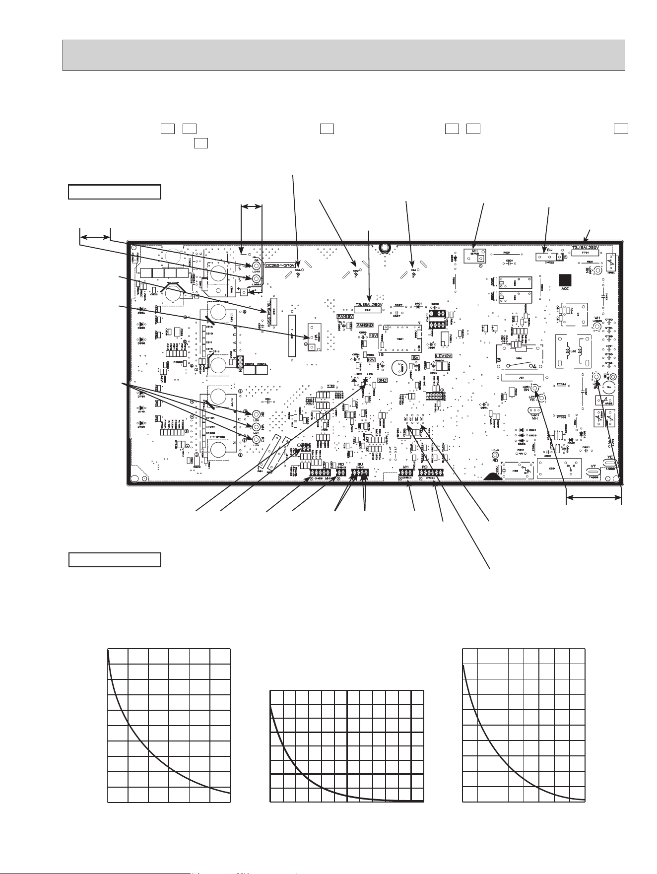
61
1. Inverter P.C. board
10-6. TEST POINT DIAGRAM AND VOLTAGE
MUZ-GL09NA -
U1
,
U8
MUZ-GL12/15NA -
U1
MUZ-GL09NAH-
U1
,
U8
MUZ-GL12/15NAH-
U1
MUY-GL09/12/15NA-
U1
Fin temperature
thermistor/RT64
(CN642)
Ambient temperature
thermistor/RT65
(CN643)
Discharge temperature
thermistor/RT62
(CN641)
Defrost thermistor
/RT61(CN641)(MUZ)
DB61
260 - 370 V DC
Front side of unit
208/230 V AC
Smoothing
capacitor (C62)
Output to
drive
compressor
(LDU,
LDV,
LDW)
(+)(-)
Fuse (F701)
T3.15AL250V
Smoothing
capacitor (C61)
Fuse (F901)
T3.15AL250V
R.V.coil/21S4
(CN721)
(MUZ)
208/230 V AC
Jumper wire for
changing defrost
setting (JS)
Signal of outdoor
fan motor (CN931)
208/230 V AC
Outdoor heat exchanger
temperature thermistor
/RT68 (CN644)
Jumper wire for pre-
heat control setting
(JK)
Heater connector
(CN722)
(MUZ-GL09/
12/15NAH)
Fuse (F801)
T3.15AL250V
Back side of unit
Expansion valve/LEV
(CN724)
Output to
drive outdoor
fan motor
(CN932)
LED
-4 14 32 50 68 86 104
0
10
20
30
40
50
60
70
80
90
100
Temperature (°F)
Defrost thermistor (RT61)
Ambient temperature thermistor (RT65)
Outdoor heat exchanger temperature thermistor (RT68)
32 50 68 86 104 122 140 158 176
0
20
40
60
80
100
120
140
160
180
200
Temperature (°F)
Fin temperature thermistor (RT64)
Resistance(kΩ)
Resistance(kΩ)
Temperature (°F)
Discharge temperature thermistor (RT62)
Resistance (kΩ)
0
100
200
300
400
500
600
700
800
32 50 68 86 104 122 140 158 176 194 212 230 248
Smoothing
capacitor (C63)
OBH733J
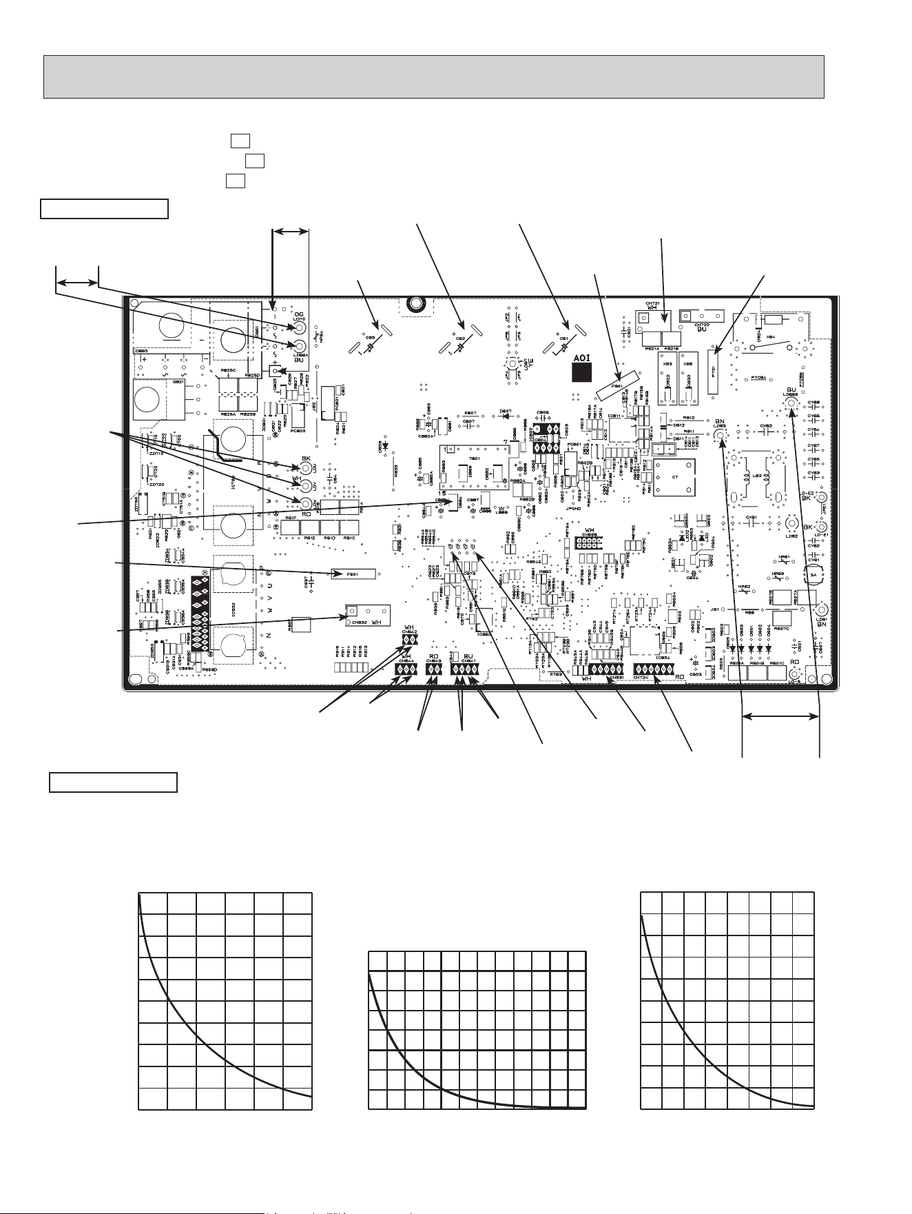
62
MUZ-GL09/12/15NA -
U2
MUZ-GL09/12/15NAH -
U2
MUY-GL09/12/15NA-
U2
-4 14 32 50 68 86 104
0
10
20
30
40
50
60
70
80
90
100
Temperature(°F)
Defrost thermistor(RT61)
Ambient temperature thermistor(RT65)
Outdoor heat exchanger temperature thermistor(RT68)
32 50 68 86 104 122 140 158 176
0
20
40
60
80
100
120
140
160
180
200
Temperature(°F)
Fin temperature thermistor(RT64)
Resistance(kΩ)
Resistance(kΩ)
Temperature (°F)
Discharge temperature thermistor (RT62)
Resistance (kΩ)
0
100
200
300
400
500
600
700
800
32 50 68 86 104 122 140 158 176 194 212 230 248
Fuse (F701)
T3.15AL250V
208/230 V AC
Fin temperature
thermistor/RT64
(CN642)
Ambient temperature
thermistor/RT65
(CN643)
Discharge temperature
thermistor/RT62(CN641)
Defrost thermistor
/RT61(CN641)
DB61
260 - 370 V DC
Front side of unit
208/230 V AC
Smoothing
capacitor (C62)
Output to
drive
compressor
(LDU,
LDV,
LDW)
(+)(-)
Smoothing
capacitor (C61)
Fuse (F901)
T3.15AL250V
R.V.coil (CN721)
208/230 V AC
Jumper wire for
changing defrost
setting (JS)
Signal of outdoor
fan motor (CN931)
Outdoor heat exchanger
temperature thermistor
/RT68 (CN644)
Jumper wire for pre-
heat control setting
(JK)
Fuse (F801)
T3.15AL250V
Back side of unit
LEV connector
(CN724)
Output to
drive outdoor
fan motor
(CN932)
LED
Smoothing
capacitor (C63)
OBH733J
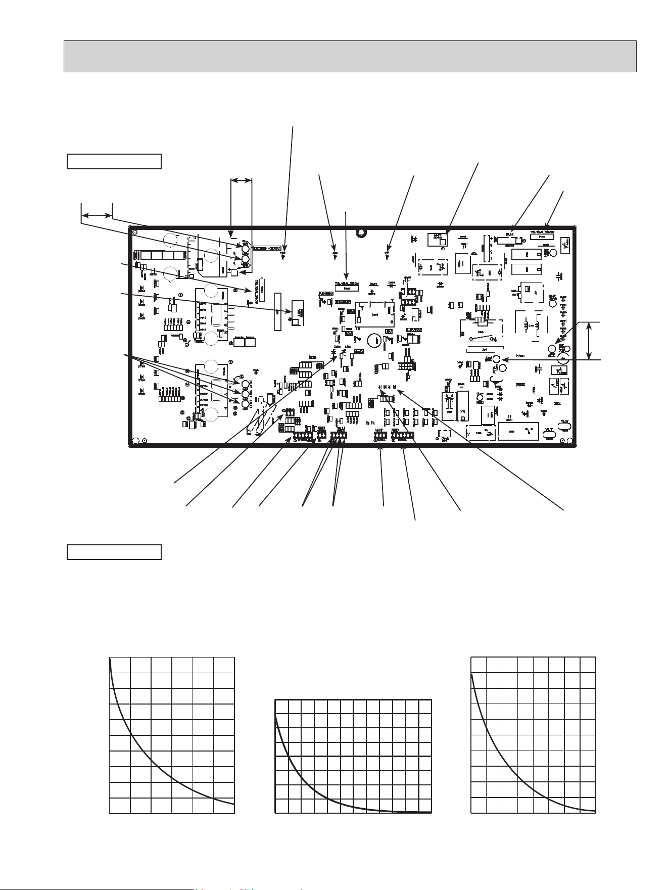
63
MUZ-GL18NA
MUZ-GL18NAH
MUY-GL18NA
-4 14 32 50 68 86 104
0
10
20
30
40
50
60
70
80
90
100
Temperature (°F)
Defrost thermistor (RT61)
Ambient temperature thermistor (RT65)
Outdoor heat exchanger temperature thermistor (RT68)
32 50 68 86 104 122 140 158 176
0
20
40
60
80
100
120
140
160
180
200
Temperature (°F)
Fin temperature thermistor (RT64)
Resistance(kΩ)
Resistance(kΩ)
Temperature (°F)
Discharge temperature thermistor (RT62)
Resistance (kΩ)
0
100
200
300
400
500
600
700
800
32 50 68 86 104 122 140 158 176 194 212 230 248
Fin temperature
thermistor/RT64
(CN642)
Ambient temperature
thermistor/RT65
(CN643)
Discharge temperature
thermistor/RT62
(CN641)
Defrost thermistor
/RT61(CN641) (MUZ)
DB61
260 - 370 V DC
208/230 V AC
Smoothing
capacitor (C62)
Smoothing
capacitor (C63)
Output to
drive
compressor
(LDU,
LDV,
LDW)
(+)
(-)
Fuse (F701)
T3.15AL250V
Smoothing
capacitor
(C61)
Fuse (F901)
T3.15AL250V
R.V.coil/21S4
(CN721)
(MUZ)
208/230 V AC
Jumper wire for
changing defrost
setting (JS)
Signal of outdoor
fan motor (CN931)
208/230
V AC
Outdoor heat exchanger
temperature thermistor
/RT68 (CN644)
Jumper wire
for pre-heat
control setting
(JK)
Heater connector
(CN722)
(MUZ-GL18NAH)
Fuse (F801)
T3.15AL250V
Back side of unit
Expansion valve/LEV
(CN724)
Output to
drive outdoor
fan motor
(CN932)
LED
Front side of unit
OBH733J
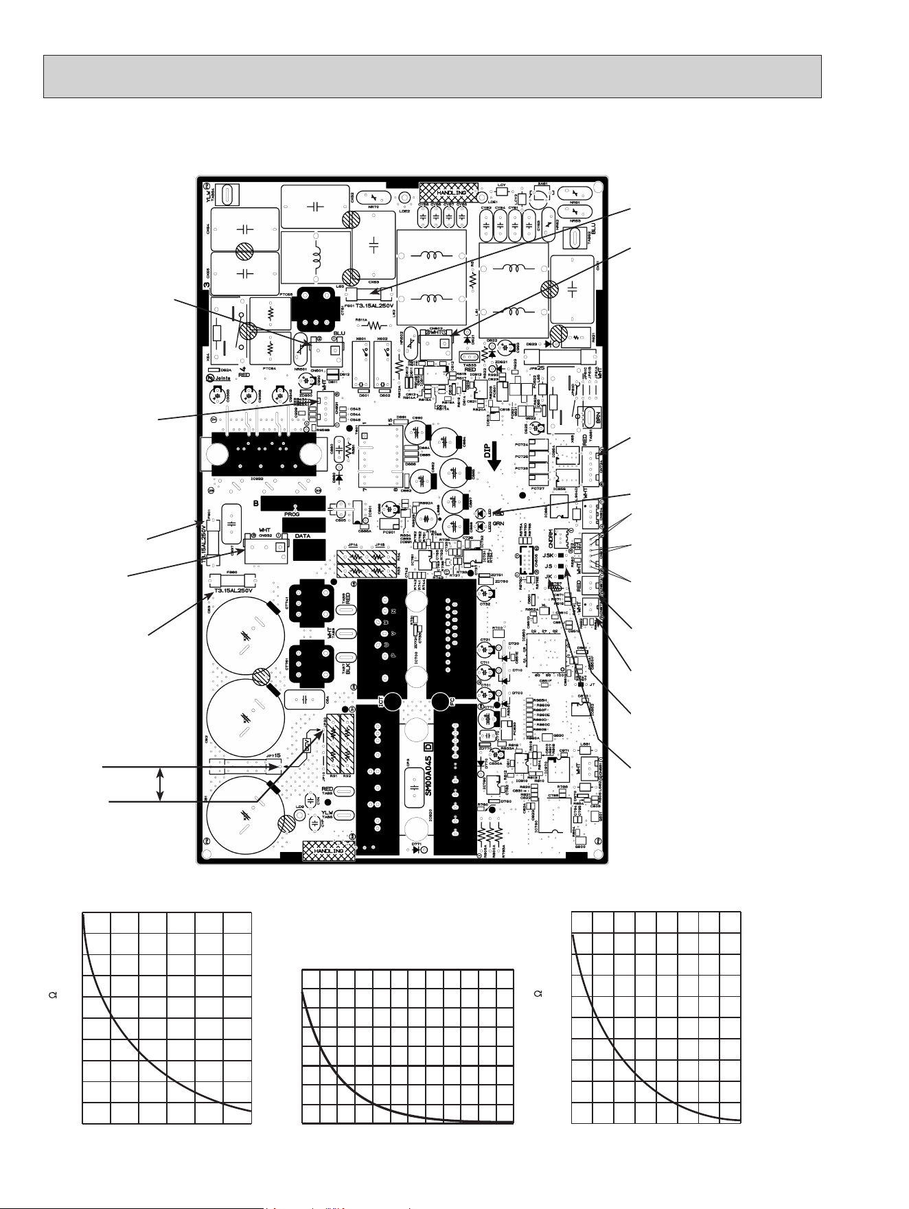
64
MUZ-GL24NA
MUZ-GL24NAH
MUY-GL24NA
Fin temperature
thermistor/RT64
(CN673)
Ambient temperature
thermistor/RT65
(CN672)
Discharge temperature
thermistor/RT62
(CN671)
Defrost thermistor
/RT61 (CN671)
(MUZ)
Output to
drive outdoor
fan motor
(CN932)
Outdoor heat exchanger
temperature thermistor
/RT68 (CN671)
Fuse (F901)
T3.15AL250V
Fuse (F880)
T3.15AL250V
Expansion valve/LEV
(CN724)
Jumper wire for
changing defrost
setting (JS)
Jumper wire for
pre-heat control
setting (JK)
Fuse (F601)
T3.15AL250V
Signal of out-
door fan motor
(CN931)
R.V. coil/21S4
(CN602)
208/230 V AC (MUZ)
294 - 370 V DC
JP715 (+)
JP30 (-)
LED
-4 14 32 50 68 86 104
0
10
20
30
40
50
60
70
80
90
100
Temperature (°F)
Defrost thermistor (RT61) (MUZ)
Ambient temperature thermistor (RT65)
Outdoor heat exchanger temperature thermistor (RT68)
32 50 68 86 104 122 140 158 176
0
20
40
60
80
100
120
140
160
180
200
Temperature (°F)
Fin temperature thermistor (RT64)
Resistance(k )
Resistance(k )
Temperature (°F)
Discharge temperature thermistor (RT62)
Resistance (kΩ)
0
100
200
300
400
500
600
700
800
32 50 68 86 104 122 140 158 176 194 212 230 248
Heater connector
(CN601)
(MUZ-GL24NAH)
OBH733J
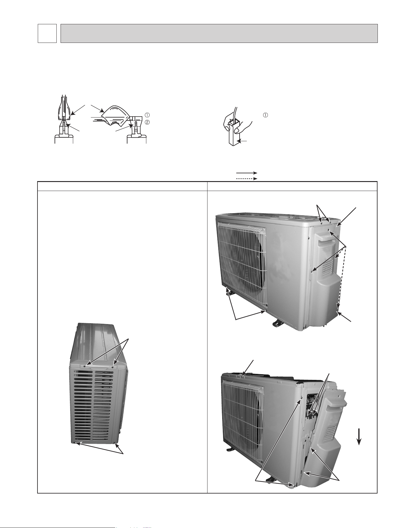
11-1. MUZ-GL09NA MUZ-GL09NAH MUY-GL09NA
MUZ-GL12NA MUZ-GL12NAH MUY-GL12NA
MUZ-GL15NA MUZ-GL15NAH MUY-GL15NA
NOTE: Turn OFF the power supply before disassembly.
OPERATING PROCEDURE PHOTOS/FIGURES
1. Removing the cabinet
(1) Remove the screw fixing the service panel.
(2) Pull down the service panel and remove it.
(3) Remove the screws fixing the conduit cover.
(4) Remove the conduit cover. (Photo 4)
(5) Remove the screw fixing the conduit plate. (Photo 5)
(6) Remove the conduit plate.
(7) Disconnect the power supply wire and indoor/outdoor
connecting wire.
(8) Remove the screws fixing the top panel.
(9) Remove the top panel.
(
10
) Remove the screws fixing the cabinet.
(
11
) Remove the cabinet.
(
12
) Remove the screws fixing the back panel.
(
13
) Remove the back panel.
Photo 2
Photo 1
Photo 3
65
(1) Slide the sleeve and check if there is a locking lever or not. (2) The terminal with the connector shown
below has the locking mechanism.
Slide the sleeve.
Pull the terminal while
pushing the locking
lever.
Hold the sleeve, and
pull out the terminal
slowly.
Connector
Sleeve
Locking lever
<Detaching method of the terminals with locking mechanism>
The terminal which has the locking mechanism can be detached as shown below.
There are 2 types of the terminal with locking mechanism.
The terminal without locking mechanism can be detached by pulling it out.
Check the shape of the terminal before detaching.
DISASSEMBLY INSTRUCTIONS
11
Back
panel
Service
panel
Screws of
the cabinet
Screws of
the top panel
Direction
to remove
Screws of
the cabinet
Hooks
Screw of the
cabinet
Screws
of the
back
panel
Screws of
the terminal block
support and the
back panel
Screws of the
top panel
Screws of the
cabinet
: Indicates the visible parts in the photos/gures.
: Indicates the invisible parts in the photos/gures.
OBH733J
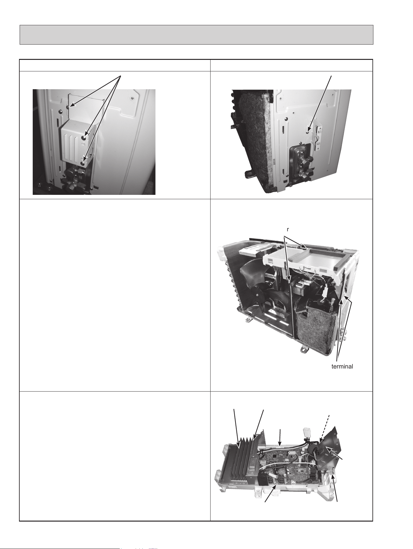
OPERATING PROCEDURE PHOTOS/FIGURES
Photo 4 Photo 5
2. Removing the inverter assembly, inverter P.C. board
(1) Remove the cabinet and panels. (Refer to section 1.)
(2) Disconnect the lead wire to the reactor and the following
connectors:
<Inverter P.C. board>
CN721 (R.V. coil) (MUZ)
CN722 (Defrost heater and heater protector) (MUZ-
GL09/12/15NAH)
CN931, CN932 (Fan motor)
CN641 (Defrost thermistor (MUZ) and discharge tempera-
ture thermistor)
CN643 (Ambient temperature thermistor)
CN644 (Outdoor heat exchanger temperature thermistor)
CN724 (LEV)
(3) Remove the compressor connector (CN61).
(4) Remove the screws fixing the heat sink support and the
separator.
(5) Remove the fixing screws of the terminal block support and
the back panel.
(6) Remove the inverter assembly.
(7) Remove the screw of the ground wire and screw of the ter-
minal block support.
(8) Remove the heat sink support from the P.C. board support.
(9) Remove the screw of the inverter P.C. board and remove the
inverter P.C. board from the P.C. board support.
Photo 6
3. Removing R.V. coil
(1) Remove the cabinet and panels. (Refer to section 1.)
(2) Disconnect the following connectors:
<Inverter P.C. board>
CN721 (R.V. coil) (MUZ)
(3) Remove the R.V. coil.
Photo 7
66
Screws of the heat sink
support and the separator
Screws of the terminal block
support and the back panel
Screws of the
conduit cover
Screw of the
conduit plate
Heat sink
Screw of the
ground wire
Screw of the
Terminal block
support
Screw of the
inverter P.C. board
Heat sink support
P.C. board
support
Terminal
block
support
*U2 model does not
have a screw on the
heat sink support.
*
OBH733J
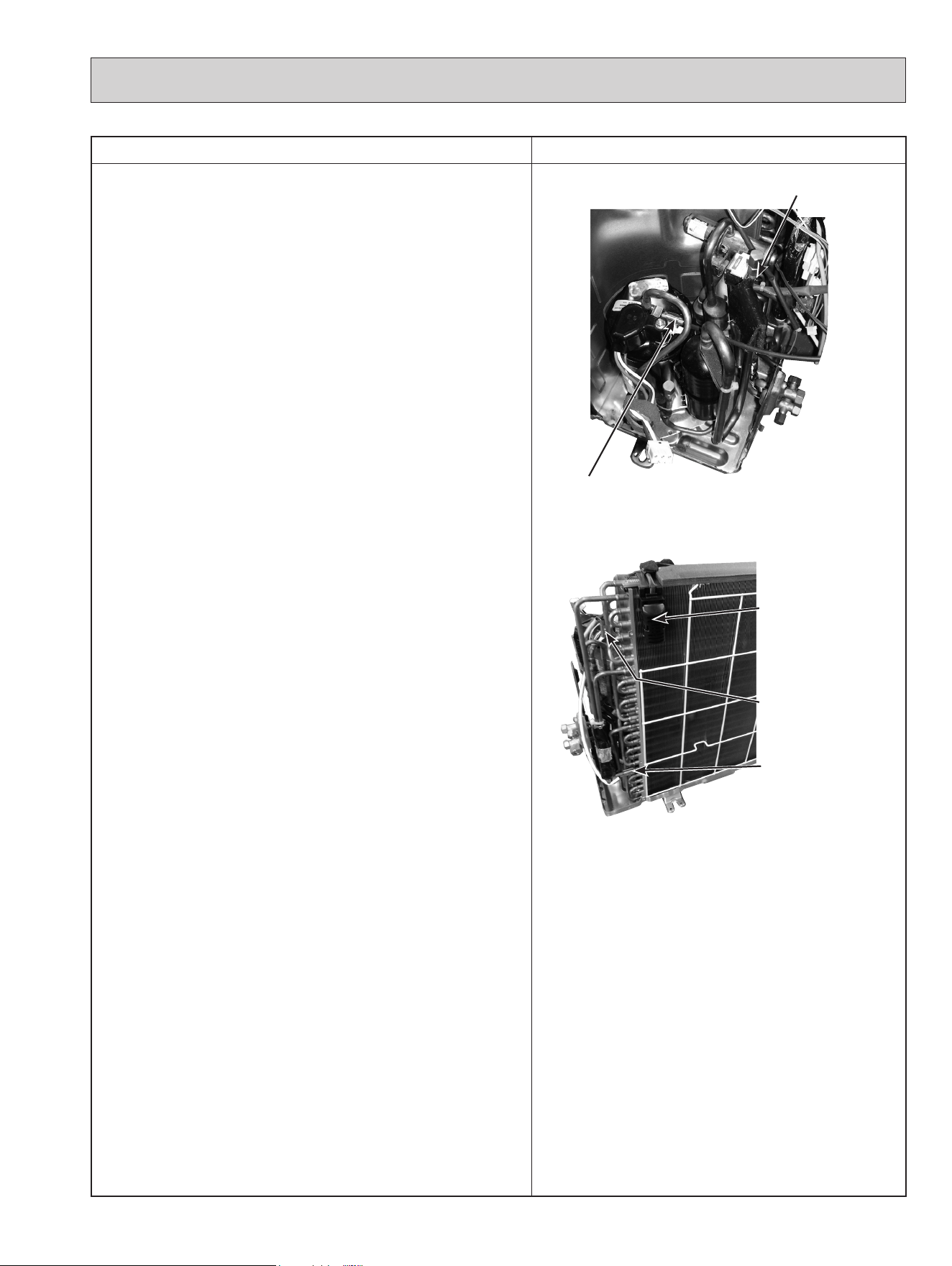
OPERATING PROCEDURE PHOTOS/FIGURES
4. Removing the discharge temperature thermistor,
defrost thermistor, outdoor heat exchanger tempera-
ture thermistor and ambient temperature thermistor
(1) Remove the cabinet and panels. (Refer to section 1.)
(2) Disconnect the lead wire to the reactor and the following con-
nectors:
<Inverter P.C. board>
CN641 (Defrost thermistor (MUZ) and discharge temperature
thermistor)
CN643 (Ambient temperature thermistor)
CN644 (Outdoor heat exchanger temperature thermistor)
(3) Pull out the discharge temperature thermistor from its holder.
(4) Pull out the defrost thermistor from its holder.
(5) Pull out the outdoor heat exchanger temperature thermistor
from its holder.
(6) Pull out the ambient temperature thermistor from its holder.
Photo 8
Photo 9
67
Discharge temperature thermistor
Screw of the
R.V. coil (MUZ)
Defrost thermistor
(MUZ)
Outdoor heat
exchanger tempera-
ture thermistor
Ambient temperature
thermistor
OBH733J
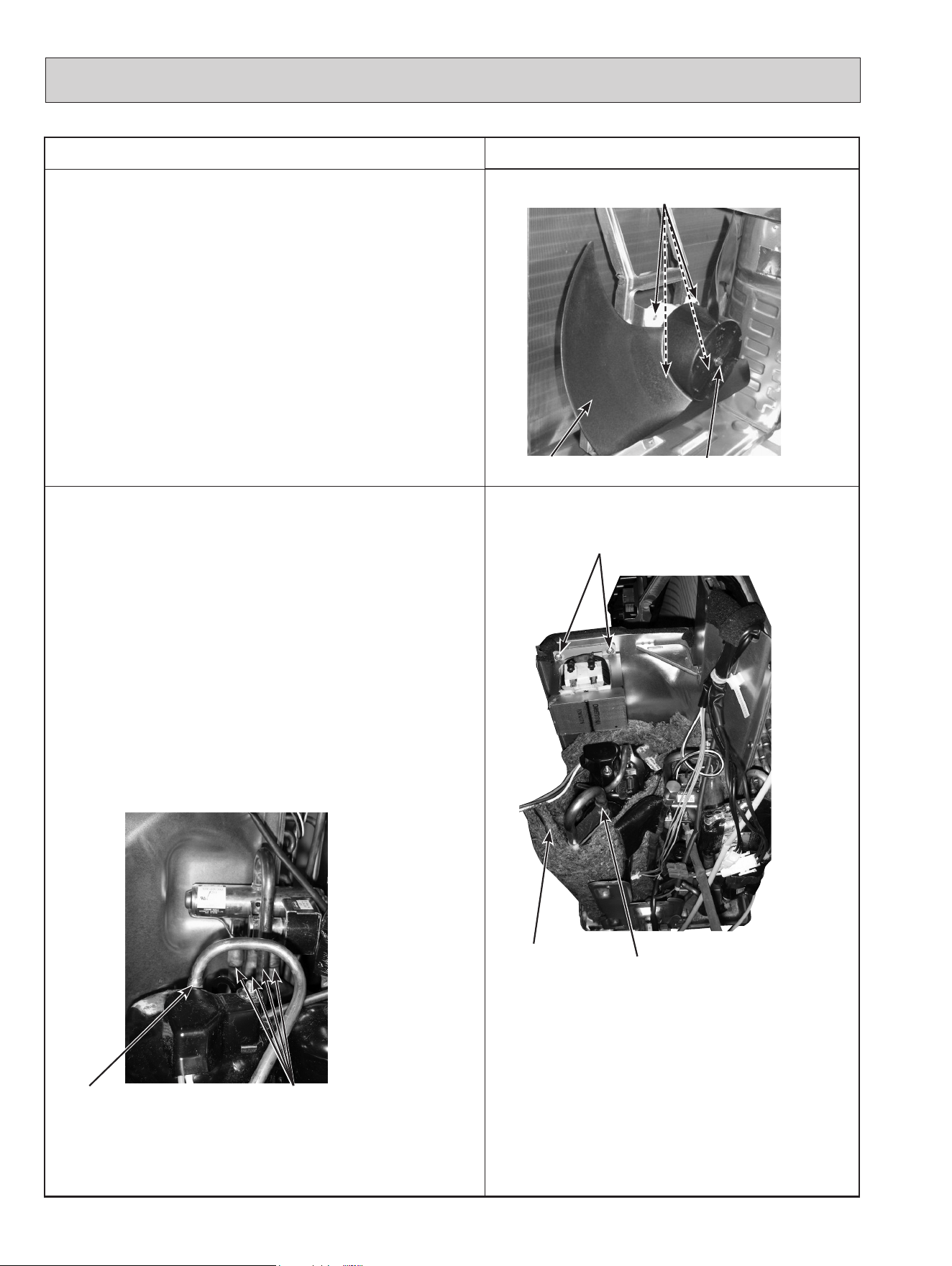
OPERATING PROCEDURE
PHOTOS/FIGURES
5. Removing outdoor fan motor
(1) Remove the cabinet and panels. (Refer to section 1.)
(2) Disconnect the following connectors:
<Inverter P.C. board>
CN931, CN932 (Fan motor)
(3) Remove the propeller fan nut.
(4) Remove the propeller fan.
(5) Remove the screws fixing the fan motor.
(6) Remove the fan motor.
NOTE: The propeller fan nut is a reverse thread.
Photo 10
6. Removing the compressor and 4-way valve
(1) Remove the cabinet and panels. (Refer to section 1.)
(2) Remove the inverter assembly. (Refer to section 2.)
(3) Remove the screws fixing the reactor.
(4) Remove the reactor.
(5) Remove the soundproof felt.
(6) Recover gas from the refrigerant circuit.
NOTE: Recover gas from the pipes until the pressure gauge
shows 0 PSIG.
(7) Detach the brazed part of the suction and the discharge pipe
connected with compressor.
(8) Remove the nuts fixing the compressor.
(9) Remove the compressor.
(
10
) Detach the brazed part of pipes connected with 4-way valve.
Photo 12
Photo 11
68
Propeller fan nut
Screws of the outdoor fan motor
Propeller fan
Screws of
the reactor
Soundproof
felt
Brazed parts of
4-way valve
Discharge pipe
brazed part
Suction pipe
brazed part
OBH733J
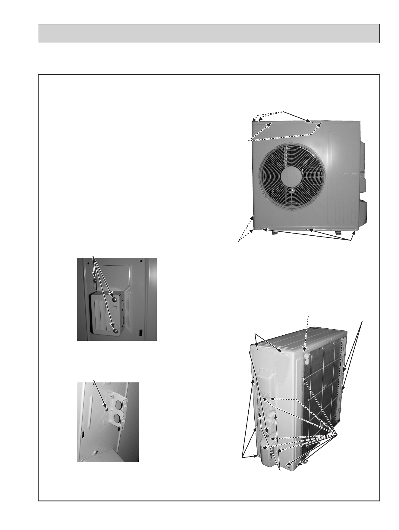
11-2. MUZ-GL18NA MUZ-GL18NAH MUY-GL18NA
NOTE: Turn OFF the power supply before disassembly.
OPERATING PROCEDURE PHOTOS/FIGURES
1. Removing the cabinet
(1) Remove the screws of the service panel.
(2) Remove the screws of the top panel.
(3) Remove the screw of the valve cover.
(4) Remove the service panel.
(5) Remove the screws fixing the conduit cover.
(6) Remove the conduit cover.
(7) Remove the screw of fixing the conduit plate.
(8) Remove the conduit plate.
(9) Remove the top panel.
(10)
Remove the valve cover.
(11)
Disconnect the power supply and indoor/outdoor connect-
ing wire.
(12)
Remove the screws of the cabinet.
(13)
Remove the cabinet.
(14)
Remove the screws of the back panel.
(15)
Remove the back panel.
Photo 3
Photo 4
Photo 1
Photo 2
69
Screws of the cabinet
Screws of the top panel
Screws of the top panel
Screw of the back panel
Screws of the cabinet
Screws of
the cabinet
Screws of the service panel
Screw of
the valve
cover
Screws of
the cabinet
Screws of
the back
panel
Screws
of the
cabinet
Screws of the conduit cover
Screw of the conduit plate
OBH733J
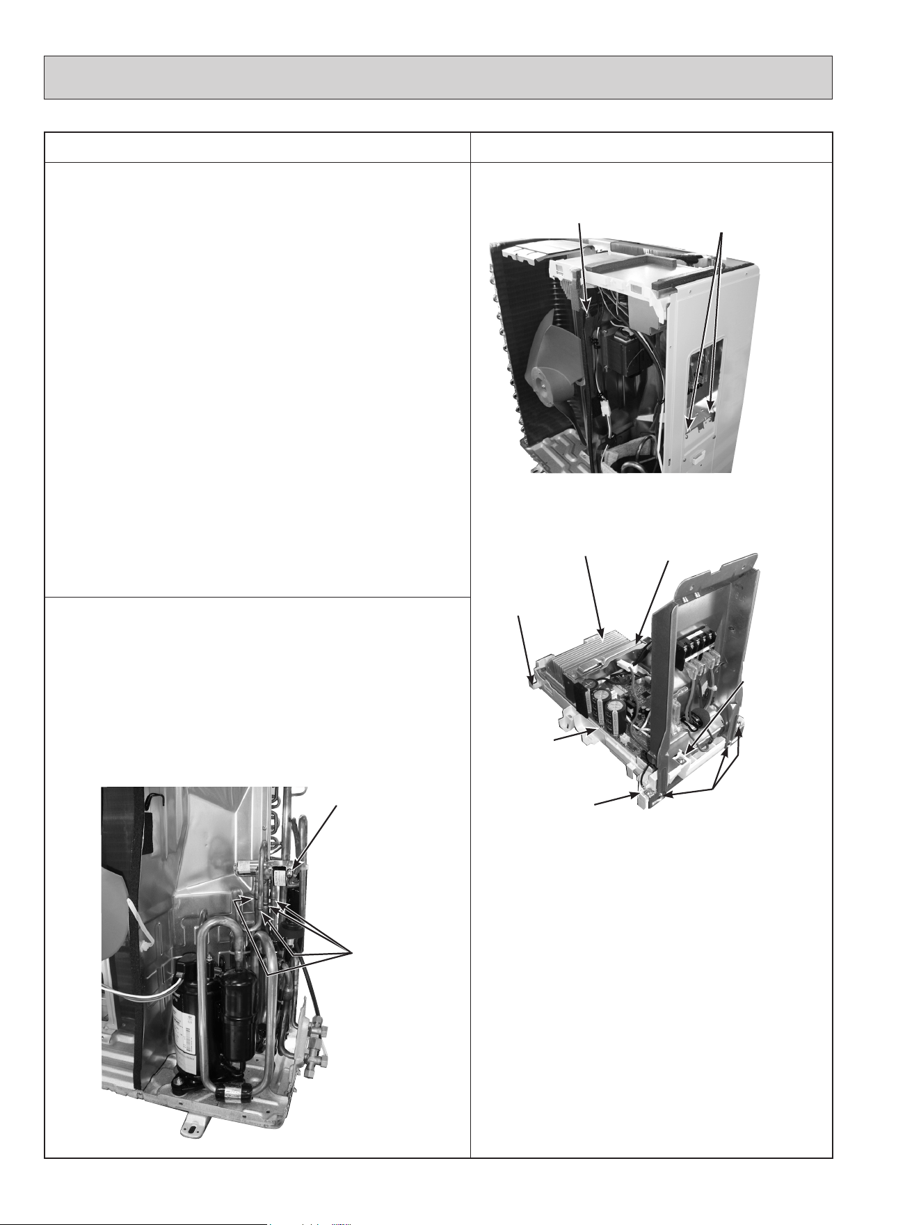
OPERATING PROCEDURE
PHOTOS/FIGURES
2. Removing the inverter assembly, inverter P.C. board
(1) Remove the cabinet and panels. (Refer to section 1.)
(2) Disconnect the lead wire to the reactor and the following con-
nectors:
<Inverter P.C. board>
CN721 (R.V. coil) (MUZ)
CN722
(Defrost heater and heater protector) (MUZ-GL18NAH)
CN931, CN932 (Fan motor)
CN641 (Defrost thermistor (MUZ) and discharge temperature
thermistor)
CN643 (Ambient temperature thermistor)
CN644 (Outdoor heat exchanger temperature thermistor)
CN724 (LEV)
(3) Remove the compressor connector.
(4) Remove the screw fixing the heat sink support and the sepa-
rator.
(5) Remove the fixing screws of the terminal block support and
the back panel.
(6) Remove the inverter assembly.
(7) Remove the screw of the ground wire, screw of the P.C.
board cover and screws of the terminal block support.
(8) Remove the heat sink support from the P.C. board support.
(9) Remove the screw of the inverter P.C. board and the inverter
P.C. board from the P.C. board support.
Photo 5
Photo 6
3. Removing R.V. coil (MUZ)
(1) Remove the cabinet and panels. (Refer to section 1.)
(2) Disconnect the following connector:
<Inverter P.C. board>
CN721 (R.V. coil) (MUZ)
(3) Remove the R.V. coil.
Photo 7
70
Screw of the heat sink
support and the separator
Brazed parts of
4-way valve
Screw of
the R.V. coil (MUZ)
Heat sink
Screw of
the inverter
P.C. board
Screw of the
ground wire
Screws of the
terminal block
support
Screw of the
P.C. board
cover
Screws of the terminal
block support and the
back panel
P.C. board
support
Heat sink
support
OBH733J
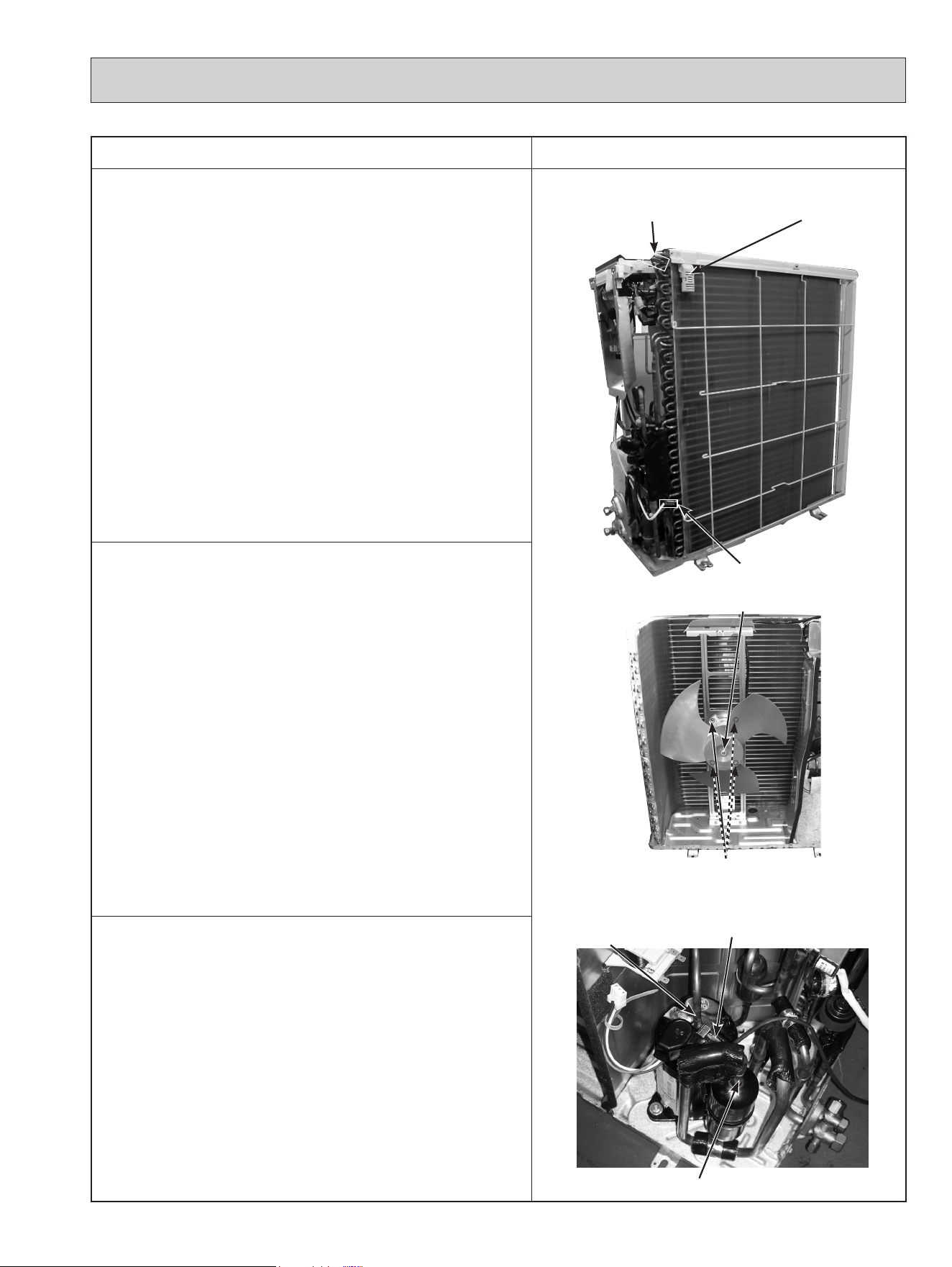
OPERATING PROCEDURE PHOTOS/FIGURES
4. Removing the discharge temperature thermistor,
defrost thermistor (MUZ), outdoor heat exchanger
temperature thermistor and ambient temperature
thermistor
(1) Remove the cabinet and panels. (Refer to section 1.)
(2) Disconnect the lead wire to the reactor and the following
connectors:
<Inverter P.C. board>
CN641 (Defrost thermistor (MUZ) and discharge tempera-
ture thermistor)
CN643 (Ambient temperature thermistor)
CN644 (Outdoor heat exchanger temperature thermistor)
(3)
Pull out the discharge temperature thermistor from its holder.
(4) Pull out the defrost thermistor from its holder.
(5) Pull out the outdoor heat exchanger temperature thermistor
from its holder.
(6) Pull out the ambient temperature thermistor from its holder.
Photo 8
Photo 9
Photo 10
5. Removing outdoor fan motor
(1)
Remove the top panel, cabinet and service panel. (Refer to
section 1.)
(2) Disconnect the following connectors:
<Inverter P.C. board>
CN931 and CN932 (Fan motor)
(3) Remove the propeller fan nut.
(4) Remove the propeller fan.
(5) Remove the screws fixing the fan motor.
(6) Remove the fan motor.
NOTE: The propeller fan nut is a reverse thread.
6. Removing the compressor and 4-way valve
(1)
Remove the top panel, cabinet and service panel. (Refer to
section 1.)
(2) Remove the back panel. (Refer to section 1.)
(3) Remove the inverter assembly. (Refer to section 2.)
(4) Recover gas from the refrigerant circuit.
NOTE: Recover gas from the pipes until the pressure gauge
shows 0 PSIG.
(5) Detach the brazed part of the suction and the discharge
pipe connected with compressor.
(6) Remove the compressor nuts.
(7) Remove the compressor.
(8) Detach the brazed part of 4-way valve and pipe. (Photo 7)
71
Screws of the
outdoor fan motor
Brazed part of the
discharge pipe
Brazed part of the suction pipe
Discharge temperature
thermistor
Outdoor heat
exchanger tempera-
ture thermistor
Ambient tem-
perature
thermistor
Defrost thermistor (MUZ)
Propeller fan nut
OBH733J
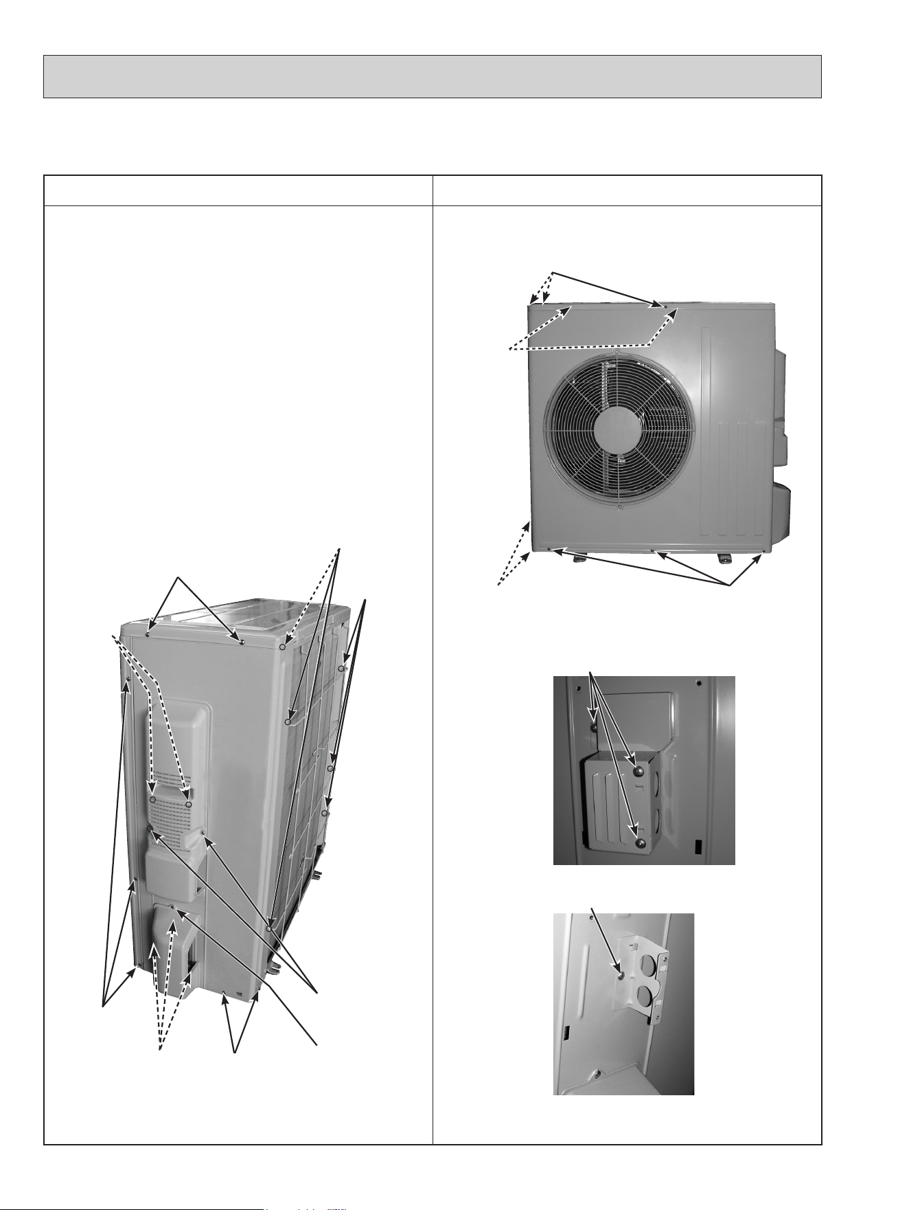
11-3. MUZ-GL24NA MUZ-GL24NAH MUY-GL24NA
NOTE: Turn OFF the power supply before disassembly.
OPERATING PROCEDURE PHOTOS/FIGURES
1. Removing the cabinet
(1) Remove the screws of the service panel.
(2) Remove the screws of the top panel.
(3) Remove the screw of the valve cover.
(4) Remove the service panel.
(5) Remove the screws fixing the conduit cover.
(6) Remove the conduit cover.
(7) Remove the top panel.
(8) Remove the valve cover.
(9) Disconnect the power supply and indoor/outdoor con-
necting wire.
(
10
) Remove the screws of the cabinet.
(
11
) Remove the cabinet.
(12)
Remove the screws of the back panel.
(13)
Remove the back panel.
Photo 2
Photo 1
Photo 3
Photo 4
72
Screws of the
top panel
Screws of the
back panel
Screws of
the service
panel
Screws of
the back
panel
Screws
of the
cabinet
Screws of the
back panel
Screws of
the back
panel
Screws of the
back panel
Screw of
the valve
cover
Screws of the
cabinet
Screws of the top panel
Screws of the
cabinet
Screws
of the
cabinet
Screws of the conduit cover
Screw of the conduit plate
OBH733J
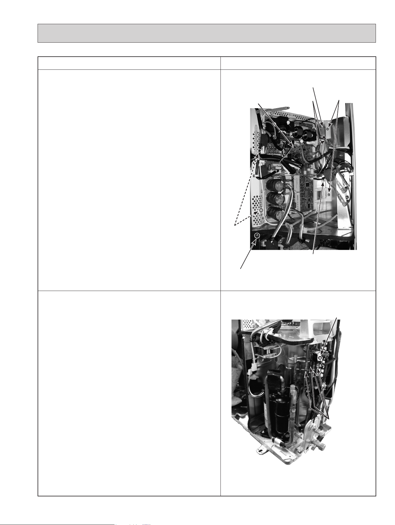
OPERATING PROCEDURE
PHOTOS/FIGURES
2. Removing the inverter assembly, inverter P.C. board
and relay P.C. board
(1) Remove the cabinet and panels. (Refer to section 1.)
(2) Disconnect the lead wire to the reactor and the following con-
nectors:
<Inverter P.C. board>
CN601 (
Defrost heater and heater protector) (MUZ-GL24NAH)
CN602 (R.V. coil) (MUZ)
CN931, CN932 (Fan motor)
CN671 (Defrost thermistor (MUZ), discharge temperature
thermistor and outdoor heat exchanger temperature
thermistor)
CN672 (Ambient temperature thermistor)
CN724 (LEV)
(3) Remove the compressor connector.
(4) Remove the screws fixing the relay panel.
(5) Remove the relay panel.
(6) Remove the ground wires and the lead wires of the inverter
P.C. board.
(7) Remove the screws of the P.B. support.
(8) Remove the inverter P.C. board from the P.B. support.
Photo 5
3. Removing R.V. coil (MUZ)
(1) Remove the cabinet and panels. (Refer to section 1.)
(2) Disconnect the following connector:
<Inverter P.C. board>
CN602 (R.V. coil) (MUZ)
(3) Remove the R.V. coil.
Photo 6
73
Brazed parts of
4-way valve
Screw of the
R.V. coil (MUZ)
Screw of the
relay panel
Screws of the
P.B. support
Inverter P.C.
board
Ground wires
Screws of
the P.B.
support
Screw of the
relay panel
Screw of the
relay panel
OBH733J
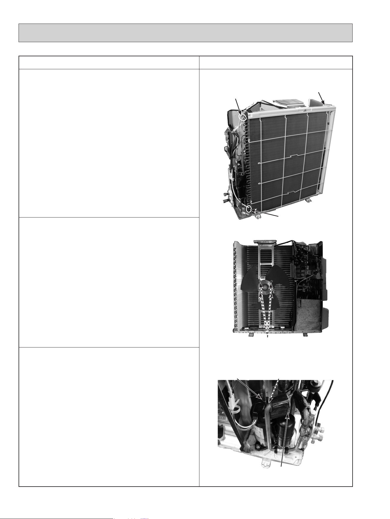
OPERATING PROCEDURE PHOTOS/FIGURES
4. Removing the discharge temperature thermistor,
defrost thermistor (MUZ), outdoor heat exchanger
temperature thermistor and ambient temperature
thermistor
(1) Remove the cabinet and panels. (Refer to section 1.)
(2) Disconnect the lead wire to the reactor and the following
connectors:
<Inverter P.C. board>
CN671 (Defrost thermistor (MUZ), discharge temperature
thermistor and outdoor heat exchanger temperature
thermistor)
CN672 (Ambient temperature thermistor)
(3)
Pull out the discharge temperature thermistor from its holder.
(4) Pull out the defrost thermistor from its holder.
(5) Pull out the outdoor heat exchanger temperature thermistor
from its holder.
(6) Pull out the ambient temperature thermistor from its holder.
Photo 7
Photo 8
Photo 9
5. Removing outdoor fan motor
(1)
Remove the top panel, cabinet and service panel. (Refer to
section 1.)
(2) Disconnect the following connectors:
<Inverter P.C. board>
CN931 and CN932 (Fan motor)
(3) Remove the propeller.
(4) Remove the screws fixing the fan motor.
(5) Remove the fan motor.
NOTE: The propeller fan nut is a reverse thread.
6. Removing the compressor and 4-way valve
(1)
Remove the top panel, cabinet and service panel. (Refer to
section 1.)
(2) Remove the back panel. (Refer to section 1.)
(3) Remove the inverter assembly. (Refer to section 2.)
(4) Recover gas from the refrigerant circuit.
NOTE: Recover gas from the pipes until the pressure gauge
shows 0 PSIG.
(5) Detach the brazed part of the suction and the discharge
pipes connected with compressor.
(6) Remove the compressor nuts.
(7) Remove the compressor.
(8)
Detach the brazed parts of 4-way valve and pipes. (Photo 6)
74
Screws of the outdoor fan motor
Brazed part of the
discharge pipe
Brazed part of
the suction pipe
Discharge temperature
thermistor
Outdoor heat exchanger
temperature thermistor
Ambient temperature
thermistor
Defrost thermistor (MUZ)
OBH733J

75
OBH733J
© Copyright 2015 MITSUBISHI ELECTRIC CORPORATION
Issued: Jun. 2021. No. OBH733 REVISED EDITION-J
Issued: Aug. 2019. No. OBH733 REVISED EDITION-H
Issued: Apr. 2019. No. OBH733 REVISED EDITION-G
Issued: Nov. 2018. No. OBH733 REVISED EDITION-F
Issued: Jul. 2017. No. OBH733 REVISED EDITION-E
Issued: Mar. 2017. No. OBH733 REVISED EDITION-D
Issued: Sep. 2016. No. OBH733 REVISED EDITION-C
Issued: Jan. 2016. No. OBH733 REVISED EDITION-B
Issued: Nov. 2015. No. OBH733 REVISED EDITION-A
Published: Sep. 2015. No. OBH733
Made in Japan
HEAD OFFICE: TOKYO BUILDING, 2-7-3, MARUNOUCHI, CHIYODA-KU, TOKYO 100-8310, JAPAN
Specifications are subject to change without notice.