Loading ...
Loading ...
Loading ...
4
INSTALL THE BLOWER
ROOF INSTALLATIONS
INSTALL THE BLOWER
WALL INSTALLATIONS
1. Remove the cover and screws.
2. Attach an appropriate U.L. approved
cable connector in the hole at the rear of
the wiring box.
3. Remove roofing nails from shingles
around the TOP and SIDES of the cutout
area only.Carefully lift the shingles to
allow the back flashing sheet on the
blower housing to fit under them.
4. Center the blower ring in the 11" diam-
eter hole, making sure that the 1¼"
diameter electrical wiring hole aligns
with the hole in the wiring box.
5. Attach the blower to the roof with six (6)
screws provided. It is recommended that
the screws be located inside the blower
housing. Drill pilot holes if necessary.
6. Using a good grade of roofing cement,
seal all of the shingles around the hous-
ing and flashing sheet as well as the
mounting screw heads.
7. Bring electrical wiring through the hole in
the wiring box and secure it according to
local codes.
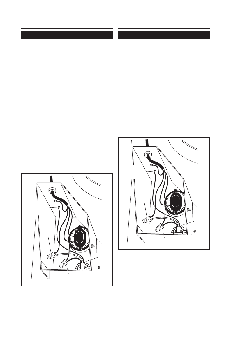
BLACK
TO
BLUE
120 VAC
LINE
IN
WHITE
TO
BROWN
GROUND
TO
GROUNDING
SCREW
8. Make the electrical connections with the
proper connector for the type of wiring
being used. Connect black to black,
white to blue, and the green or bare wire
to grounding screw.
9. Replace cover and screws. Do not pinch
wiring under the cover.
10. Make sure damper opens and closes
freely.
1. Place a large bead of caulk on the back
side of the housing all along the outer
edges.
2. Center the blower ring in the 11" diam-
eter hole, making sure that the 1¼"
diameter electrical wiring hole aligns
with the hole in the wiring box.
3. Attach blower to the wall with the six (6)
screws provided. It is recommended that
the screws be located inside the blower
housing. Drill pilot holes if necessary.
4. Using a good grade of caulk, seal all
around the mounting screw heads.
5. Bring electrical wiring through the hole in
the wiring box and secure it according to
local codes.
BLACK
TO
BLUE
120 VAC
LINE
IN
WHITE
TO
BROWN
GROUND
TO
GROUNDING
SCREW
6. Make the electrical connections with the
proper connector for the type of wire
being used. Connect black to black,
white to blue and green or bare wire to
grounding screw.
7. Replace cover and screws. Do not pinch
wiring under cover.
8. Make sure damper opens and closes
freely.
9. Top and side flanges of the back plate
may be covered with trim strips. Do not
block grille opening at bottom with trim.
It will adversely affect performance of
the blower.
WHITE
TO
BLUE
WHITE
TO
BLUE
BLACK
TO
BLACK
BLACK
TO
BLACK
Loading ...
Loading ...
Loading ...