Loading ...
Loading ...
Loading ...
Owner’s Manual for Portable Generator 11
5. See Figure 3-2. When engine starts, rotate
Off/Run/Choke dial to RUN (2). Choke
operation is reduced as Off/Run/Choke
dial is rotated towards RUN.
NOTE: If engine fires, but does not continue to
run, rotate the Off/Run/Choke dial to OFF and
repeat starting instructions.
IMPORTANT NOTE: Do not overload gener-
ator or individual panel receptacles. See
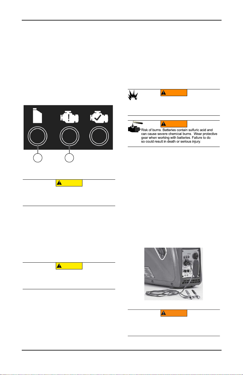
Figure 3-3. If an overload occurs, the over-
load LED (A) will illuminate and AC output
ceases. To correct, see Generator Status
Lights. Read Know Generator Limits care-
fully.
.
Figure 3-3.Shutdown Fault
Generator Shut Down
1. Shut off all loads and unplug electrical
loads from generator panel receptacles.
2. Let engine run at no-load for several min-
utes to stabilize internal temperatures of
engine and generator.
3. See Figure 3-2 Rotate Off/Run/Choke dial
to OFF (3).
4. Turn fuel cap OFF.
Restarting Hot Engines
1. See Figure 3-2. Turn Off/Run/Choke dial
from STOP to RUN. This will open the fuel
valve and permit starting.
2. Firmly grasp recoil handle and pull slowly
until increased resistance is felt. Pull rap-
idly up and away.
Low Oil Level Shutdown System
The engine is equipped with a low oil level
sensor that shuts down the engine automati-
cally when the oil level drops below a speci-
fied level to prevent engine damage. See
Figure 3-3 (B). The engine will not run until the
oil has been filled to the proper level.
If the engine shuts down and there is sufficient
fuel, check engine oil level.
Charging a 12 VDC Battery
NOTE: A battery may lose some of its charge
when not in use for prolonged periods of time.
The DC charging output is not regulated. The
circuit protector does not prevent over
charging a battery. Battery charging should be
done in a dry location.
1. Start generator and turn Economy switch
OFF.
2. Plug Battery Charging Cable into Battery
Charger Output jack, located on the con-
trol panel. See Figure 3-4.
3. Connect positive (+) battery clamp (red
wire) to battery FIRST.
4. Connect negative (-) battery clamp (black
wire) to battery SECOND.
NOTE: This receptacle can not recharge 6-
volt batteries and can not be used to crank an
engine having a discharged battery.
Figure 3-4. Battery Charger Input Jack
002335
AB
(000136)
CAUTION
Equipment and property damage. Disconnect electrical
loads prior to starting or stopping unit. Failure to do so
could result in equipment and property damage.
(000136)
CAUTION
Equipment and property damage. Disconnect electrical
loads prior to starting or stopping unit. Failure to do so
could result in equipment and property damage.
(000137a)
WARNING
Explosion. Batteries emit explosive gases while charging.
Keep fire and spark away. Wear protective gear when
working with batteries. Failure to do so could result in
death or serious injury.
(000138a)
WARNING
004469
WARNING
Environmental Hazard. Always recycle batteries at an
official recycling center in accordance with all local
laws and regulations. Failure to do so could result in
environmental damage, death or serious injury.
(000228)
Loading ...
Loading ...
Loading ...