Loading ...
Loading ...
Loading ...
9
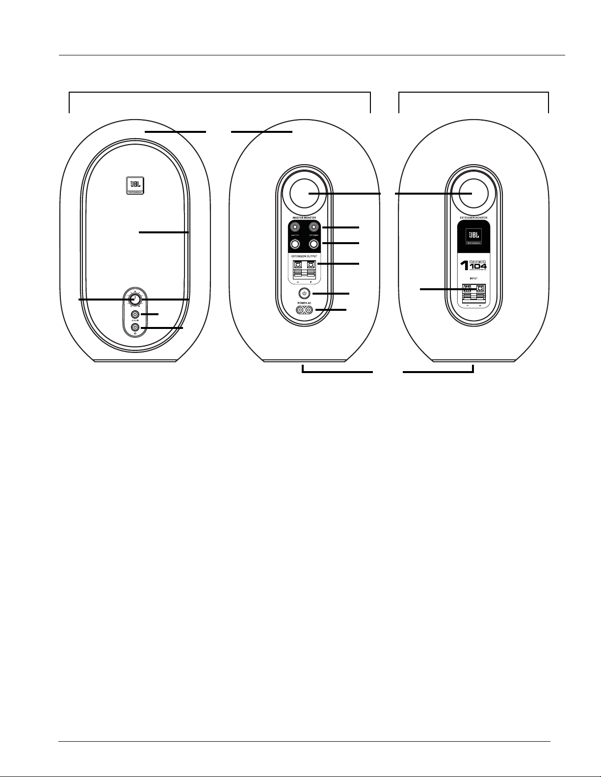
Master Monitor
Front Rear
Extension Monitor
Rear
1
6
14
7
8
9
10
11
12
2
4
5
3
13
8. 6.5 MM (1/4”) TRS INPUTS – Connect professional equipment to these inputs using balanced or
unbalanced 6.5 mm (1/4”) cables.
NOTE: Signal connected to the TRS (Tip Ring Sleeve) input labelled "MASTER" will be reproduced by
the MASTER MONITOR. Signal connected to the TRS input labelled "EXTENSION" will be reproduced by
the EXTENSION MONITOR. These inputs are designed to accept signals with a +4 dBu nominal level, or
lower.
9. EXTENSION OUTPUT – Connect this output to the EXTENSION MONITOR using the included speaker
wire. This output sends an amplied speaker-level signal to the EXTENSION MONITOR.
10. POWER SWITCH – Activates power for the system.
11. POWER INLET – Connect the included AC power cord to this inlet.
12. ENCLOSURE – The hard-shell enclosure provides the acoustic volume required by the monitors for
accurate reproduction. The MASTER MONITOR enclosure also houses the power amplier and electrical
components.
13. EXTENSION INPUT – Connect this input to the MASTER MONITOR EXTENSION OUTPUT terminals
using the included speaker wire. This input receives an amplied speaker-level signal from the MASTER
MONITOR.
14. ISOLATION PAD – A rubber isolation pad on the bottom of each monitor minimizes mechanical
interaction between the speaker and the work surface, reducing acoustic resonance and optimizing
playback performance.
NOTE: Important product information, including the serial number, is printed and can be viewed on the
MASTER MONITOR isolation pad.
Loading ...
Loading ...
Loading ...