Loading ...
64 and 67C Series Regulators
2
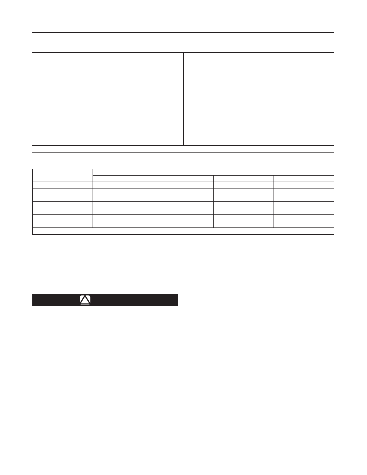
Table 2. Outlet Pressure Ranges
SPRING RANGE,
PSIG (bar)
(1)
TYPE NUMBER AND FACTORY SETPOINT, PSIG (bar)
67CW, 67CD, and 67CH 67CN 64SR 64 and 64KB
3 to 15 (0,21 to 1,0) - - - - - - - - 10 (0,69) 10 (0,69)
3 to 20 (0,21 to 1,4) 15 (1,0) - - - - 15 (1,0) 15 (1,0) 64KB only
5 to 35 (0,34 to 2,4) 20 (1,4) 10 (0,69); 15 (1,0); or 20 (1,4) 20 (1,4) 20 (1,4)
20 to 50 (1,4 to 3,4) 40 (2,8) 67CD only - - - - - - - - - - - -
30 to 60 (2,1 to 4,1) 40 (2,8) 67W and 67CH only - - - - - - - - 40 (2,8)
35 to 100 (2,4 to 6,9) 50 (3,4) 67CD only - - - - - - - - 50 (3,4)
35 to 135 (2,4 to 9,3) 50 (3,4) 67W and 67CH only - - - - - - - - - - - -
1. All springs can be backed off to 0 psig (0 bar) except Type 67CN. However, for the highest capacity and most accurate control, use the lowest spring that can be adjusted to the required setpoint.
Never use a 64 or 67C Series (pounds to pounds)
regulator on low-pressure (inches of water
column) service.
1. Regulator operation within ratings does not preclude the
possibility of damage from debris in the lines or from external
sources. Regulators should be inspected for damage
periodically and after any overpressure condition.
2. Only personnel qualied through training and experience
should install, operate, and maintain a regulator. Make sure
that there is no damage to or foreign material in the regulator.
Also, ensure that all tubing and piping is free of debris.
3. Install the regulator so that ow is from the IN to the OUT
connection as marked on the regulator body.
4. Protect the regulator from vehicular trafc or damage from
other external sources.
5. Install the regulator high enough above ground level, at least
18-inches (457 mm), so that rain splatter cannot freeze in the
vent. Do not install the regulator in a location where there can
be excessive water accumulation or ice formation, such as
directly beneath a downspout, gutter, or roof line or a building.
6. A regulator installed outdoors without a protective hood must
have its vent pointed vertically down to prevent clogging and
moisture accumulation. A clogged spring case vent hole may
cause the regulator to function improperly. To keep this
vent hole from being plugged (and to keep the spring case
Specications
Some general 64 and 67C Series ratings and other specications
are given on Specications section. A spring case label gives the
spring range for the regulator as it comes from the factory.
Installation
!
WARNING
Failure to follow these instructions and warnings
could result in personal injury or property damage.
All vents should be kept open to permit free ow
of air into and out of the regulator.
Protect openings against the entrance of rain,
snow, ice formation, paint, mud, insects, or any
other foreign material that could plug the vent or
vent lines.
LP-Gas may discharge to the atmosphere through
the vent of a Type 64SR. The internal relief valve
of the Type 64SR regulator does not provide
full overpressure protection, but is designed for
minor seat leakage only. An obstructed vent
which limits air or gas ow can cause abnormally
high outlet pressure. A vent line to a remote,
safe location outdoors is required on permanent
indoor installations or on installations where
there can be a hazardous accumulation of gas.
1. The pressure/temperature limits in this Instruction Manual or any applicable standard limitation should not be exceeded.
Specications
Body Sizes, Inlet and Outlet Connection Style
64 Series: 1/2-inch NPT, inlet and outlet
67C Series: 1/4-inch NPT, inlet and outlet
Side Outlet Connection Style (Plugged)
1/4-inch NPT; pressure gauge can be installed
Maximum Inlet Pressure (Body Rating)
(1)
250 psig (17,2 bar)
Maximum Emergency Outlet Pressure
(1)
64 Series: 220 psig (15,2 bar)
67C Series: 50 psig (3,4 bar) over outlet pressure
Pressure Registration
Internal
Wide-Open Flow Coefcients
64 Series: C
g
: 35.6; C
v
: 0.36; C
1
: 39.0
67C Series: C
g
: 11.7; C
v
: 0.36; C
1
: 32.2
Regulator Temperature Capabilities
64 Series: -20° to 150°F (-29° to 66°C)
67C Series: -20° to 180°F (-29° to 82°C)
Spring Case Vent Location
64 Series: 1/4-inch NPT screened over side outlet tap
67C Series: Aligned with inlet, other positions optional
Approximate Unit Weights
64 Series: 2.25 pounds (1 kg)
67C Series: 1 pound (0,5 kg)
Loading ...
Loading ...