USER’S GUIDE
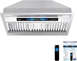
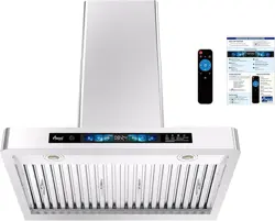
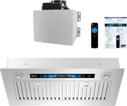
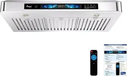
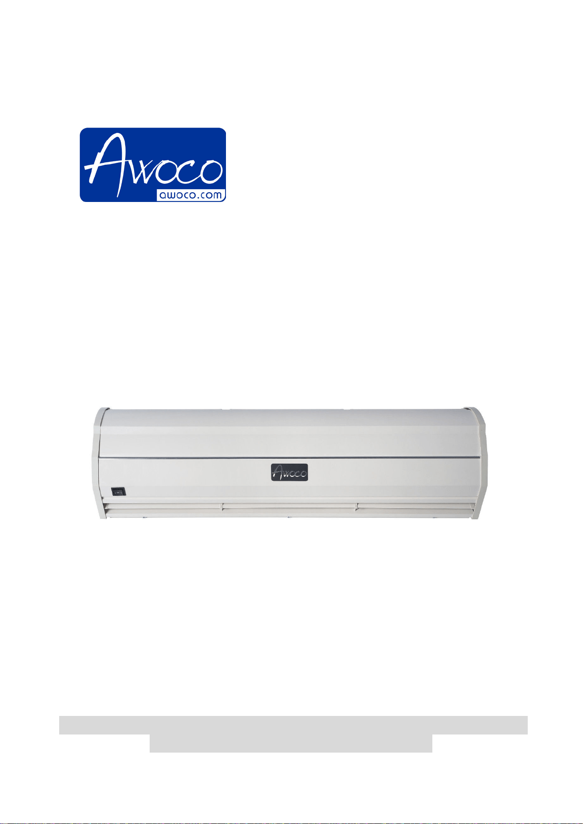
AIR CURTAINS
Models: FM-3509-L/Y, FM-3510-L/Y,
FM-3512-L/Y, FM-3515-L/Y
Thanks for purchasing this Air Curtain.
PLEASE READ AND SAVE THESE INSTRUCTIONS.
Strongly recommend to test the unit before installation for any
defective or damage during shipment.

1
WARNING – TO REDUCE THE RISK OF FIRE, ELECTRIC SHOCK, OR INJURY
TO PERSONS, OBSERVE THE FOLLOWING:
A. Always disconnect, lock and tag power source before installing or servicing. Failure to
disconnect power source can result in fire, shock or serious injury.
B.
Installation work and electrical wiring must be done by qualified person(s) in
accordance with all applicable codes and standards, including fire-rated construction.
C. When cutting or drilling into wall or ceiling, do not damage
electrical wiring and other
hidden utilities.
D. To reduce the risk of fire or electric shock, do not use this fan with any solid-state
speed control device
E. Repair and maintenance operations can only be performed by qualified personnel.
F. Verify and ensure th
e rated voltage and frequency (please refer to the rating label) of
the air curtain is in compliance with the mains supply.
CONTENTS
1. PRODUCT INTRODUCTIONS ................................................................................................ 1
2. INSTALLATION DIMENSIONS ................................................................................................ 2
3. INSTALLATION CAUTIONS .................................................................................................... 3
4. INSTALLATION INSTRUCTIONS............................................................................................ 4
5. TECHNICAL PARAMETER ..................................................................................................... 5
6. WIRING DIAGRAM ................................................................................................................. 6
7. OPTIONAL DOOR MICRO SWITCH INSTALLATION ............................................................. 6
8. OPERATING INSTRUCTIONS ................................................................................................ 8
9. MAINTENANCE AND CLEANING ........................................................................................... 8
10. SUPPORT AND CONTACT ................................................................................................. 8
1. PRODUCT INTRODUCTIONS
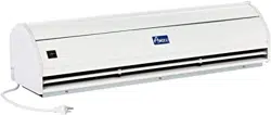
Air curtains are widely installed at the entrances of supermarket, theater, meeting room, hotel,
office room, storeroom etc. They can reduce penetration of insects, dust…unconditioned air into a
conditioned space by forcing an air stream over the entire entrance to create a comfortable
environment for you.
2
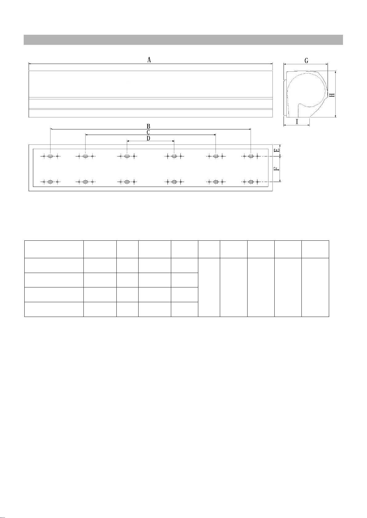
2. INSTALLATION DIMENSIONS
UNIT: inch
Note: the data are subjected to change without notice due to product development.
MODEL A B C D E F G H I
FM-3509-L/Y
35.43 --- 27.36 ---
2.91 3.94 8.46 9.06 4.84
FM-3510-L/Y
42.00 --- 27.36 ---
FM-3512-L/Y
47.24 --- 38.98 11.61
FM-3515-L/Y
59.06 --- 50.59 19.84
3
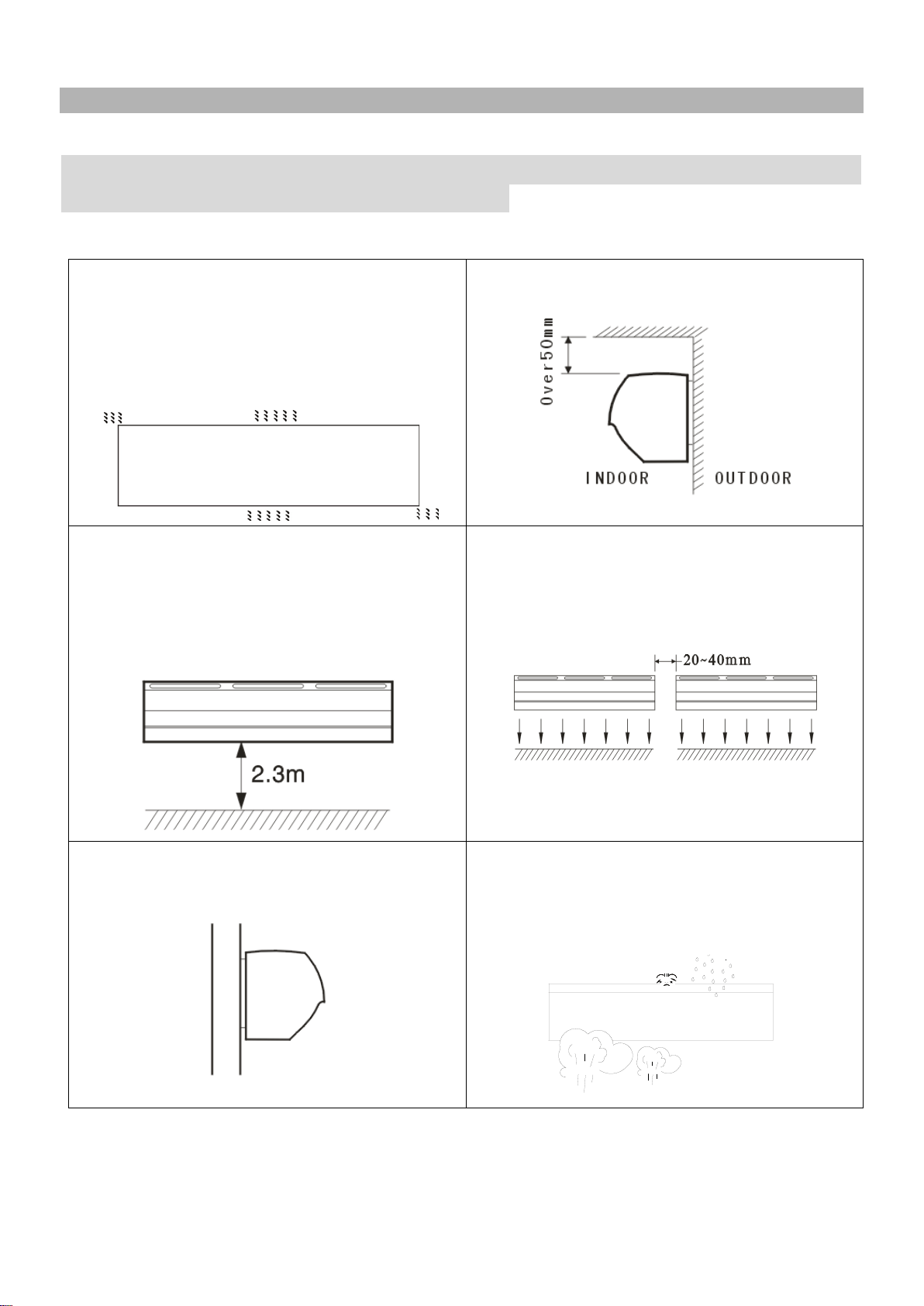
3. INSTALLATION CAUTIONS
Must observe the following when installing air curtains:
Strongly recommend to test the unit before installation for any
defective or damage during shipment.
3.1 Please install the unit on a sturdy
supporting structure to avoid
shaking and
ensure its security (because the unit running
may cause the wall to become loose or
shake and make noise).
3.2 Please install the unit inside the room.
3.3 Don’t install the unit too low, no less than
2.3 meters from the ground.
ATENCIÓN
:
No instale la unidad
demasiado bajo, no menos de 2,3 metros
del suelo.
3.4 When the entrance is wider than the
unit, it is recommended to install two or
more units in parallel. In this case, provide
20-40mm gaps between the units.
3.5 Don’t allow gaps between the unit and
the wall.
3.6 Don’t install the unit at a place where it
is splashed by water, exposed to excessive
steam, explosive gas or corrosive gas.
4
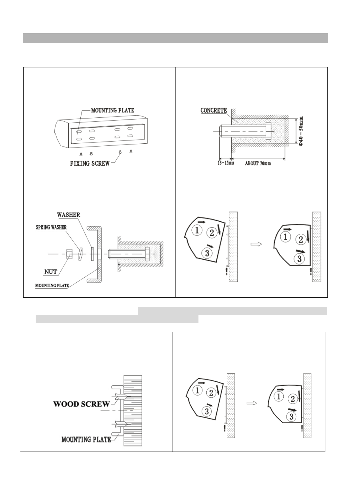
4. INSTALLATION INSTRUCTIONS
A. Installing on the concrete wall:
4.1.1 Unscrew the fixing screws to remove
the mounting plate from the back of the main
body.
4.1.2 Determine the mounting location with
the mounting plate. Secure the bolts in
place. (Fill cement into the bolt holes if
needed)
4.1.3 Tighten the nuts to secure the
mounting plate to the wall after cement
setting (use the washers and nuts as the Fig
shows).
4.1.4 Hang the main body onto the upper
end of the mounting plate, and then tighten
the bottom fixing screws
back to the
mounting plate.
B. Installing on the wooden wall: (Note: make sure the screws are secured in the wood,
attach an extra wood frame to the wall if needed.)
4.2.1 Refer to step 4.1.1 and determine the
mounting location, then securely mount the
mounting plate to the wooden wall with tapping
screws.
4.2.2 Hang the main body onto the upper end
of the mounting plate, and then tie the bottom
fixing screws back to the mounting plate.
5
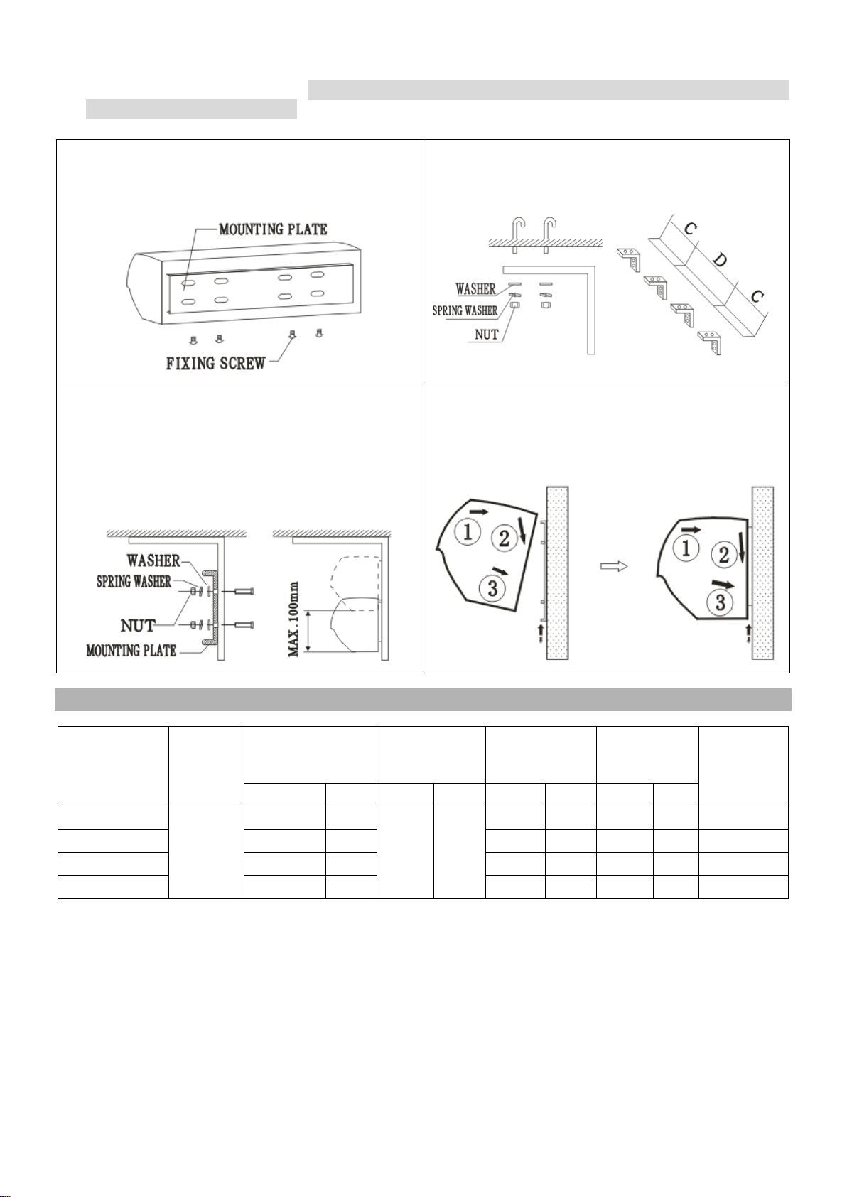
C. Installing from the ceiling: (Note: this installation is NOT recommended; the ceiling
brackets are not supplied.)
4.3.1 Remove the mounting plate from the main
body as per the step 4.1.1
4.3.2 Securely mount the ceiling brackets (not
included) as the Fig shows.
4.3.3 Fix the mounting plate to the ceiling
brackets and tighten it securely as the Fig
shows. The position of the mounting plate can
be adjusted in vertical direction
according to
need, but the max distance is 100mm.
4.3.4 Hang the main body onto the upper end
of the mounting plate, and then tie the bottom
fixing screws back to the mounting plate.
5. TECHNICAL PARAMETER
Model
No.
Voltage
(V~Hz)
Power
(W)
Max air
velocity
(FPM)
Air volume
(m
3
/h)
Noise level
(dB)
Net weight
(Lb)
H L H L H L H L
FM-3509-L/Y
120V,
60Hz
300 270
3150 2559
1100 900 52 49 28.7
FM-3510-L/Y
320
300
1200
1000
52
49
30.9
FM-3512-L/Y
400
360
1500
1200
53
50
34.2
FM-3515-L/Y
500
470
1900
1500
55
52
44.1
Note: the data are subjected to change without notice due to product development.
6
6. WIRING DIAGRAM
GREEN
GREEN
GREEN
WHITE
ORANGE
(YELLOW)
(YELLOW)
ORANGE
WHITE
Lo
OFF
K
BLACK
THERMAL
CUT-OUT
THERMAL
CUT-OUT
BLACK
THERMAL
CUT-OUT
BLACK
BROWN
BLUE
L
N
DOUBLE SPEED SWITCH WIRING DIACRAM
GREEN
WHITE
Hi
BLUE
BLUE
BLUE
GREY
WHITE
YELLOW
(YELLOW)
ORANGE
YELLOW
C
YELLOW
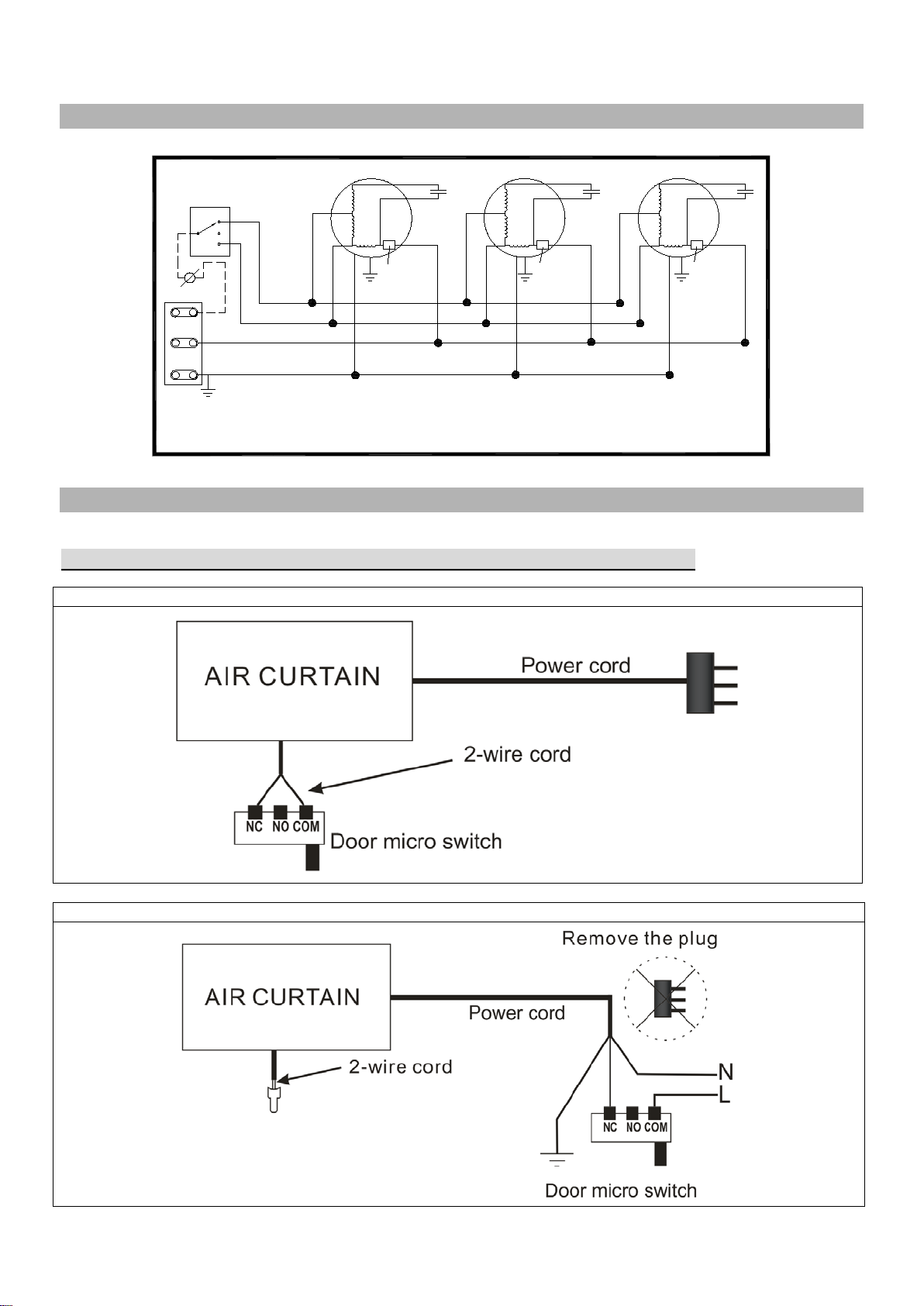
7. OPTIONAL DOOR MICRO SWITCH INSTALLATION
Please purchase the door micro switch if not supplied with the product.
Note: consult with your electrical professional for electrical connection.
Option 1: Open the provided 2-wire cord, extend and connect the wires to the door micro switch
Option 2: Connect the door micro switch into the Hot Line (L) wire of the power cord
7
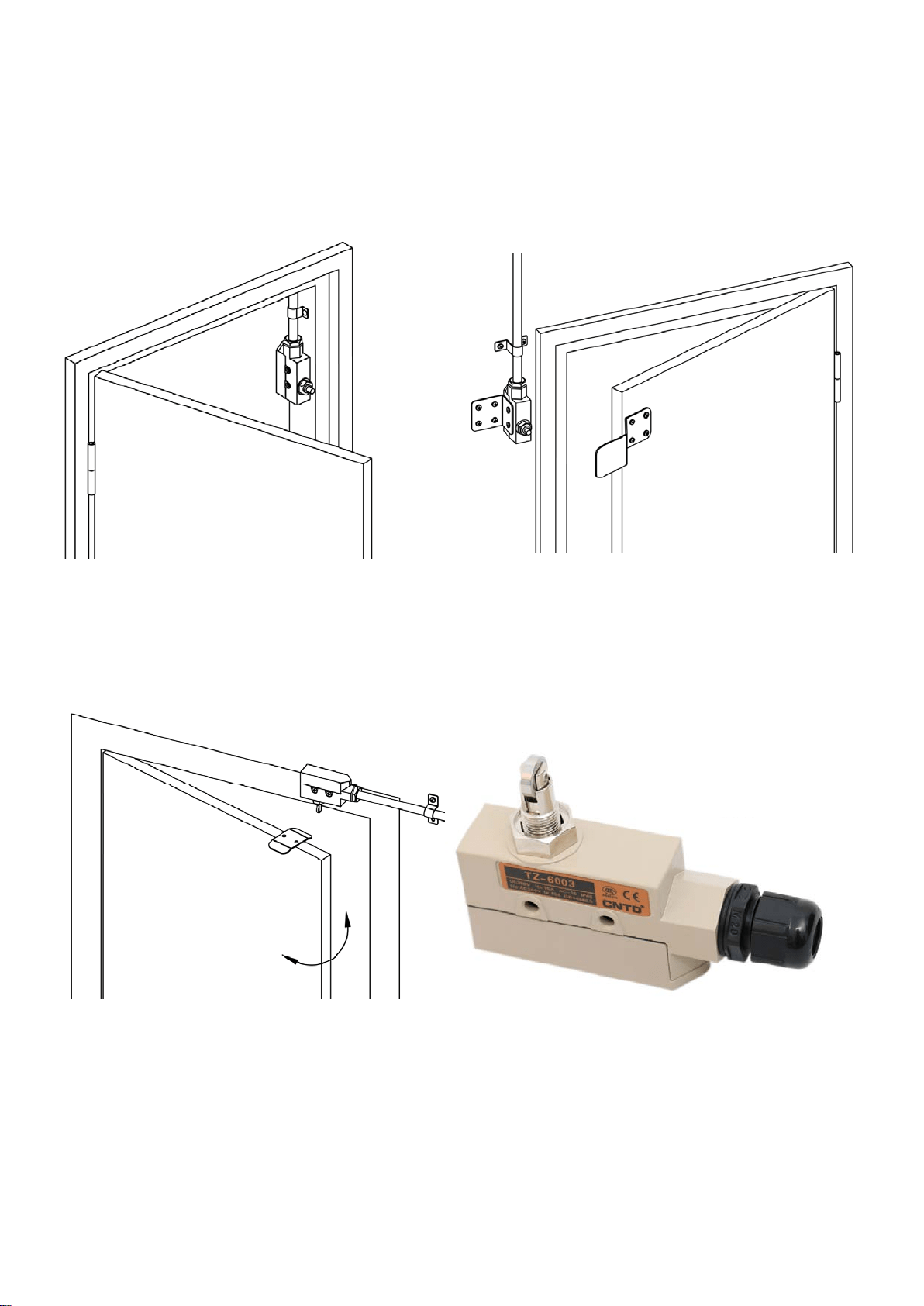
The air curtain should be installed indoor, please follow the below diagrams for the recommended
installation.
7.1 If the door swings outward, mount the micro switch (model TZ-6001 or TZ-6003) on side of the
door frame (or the upper side of door frame).
7.2 If the door swings inward, please use metal sheet to create the brackets (not included) as
shown in above to install the micro switch (model TZ-6001 or TZ-6003).
7.3 If the door swings in and out, please place the micro switch with Roller Plunger (model
TZ-6003) on the upper side of the door frame with a metal bracket (not included) mounted on the
top of the door as show below.
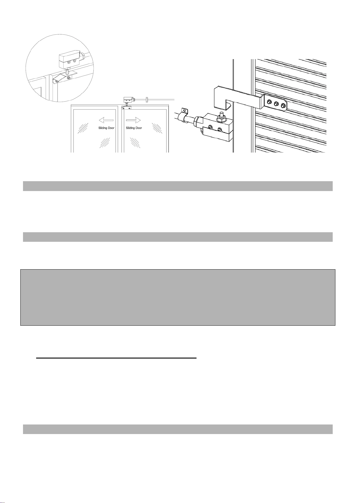
7.4 Refer to the below micro switch installation 2 diagrams for Sliding Door (micro switch model
TZ-6002) and Roll-up Door (micro switch model TZ-6001 or TZ-6003).
Outdoor Wall
Indoor Wall
(Air Curtain Installed)
Door swings
outward
Door swings
inward
Door bracket
(not included)
Switch bracket
(not included)
Mounted on
door frame
Door swings
in & out
Mounted on
door frame
Door bracket
(not included)
Door Micro Switch
with Roller Plunger
Model TZ-6003
8
8. OPERATING INSTRUCTIONS
8.1 Connect power to the unit.
8.2 Push the power switch to the left/right to switch on the unit. [L] - Low speed, [H] - High speed.
8.3 Adjust the air deflector to obtain optimum effect.
9. MAINTENANCE AND CLEANING
WARNING:
A. Any service is to be performed only by qualified personnel who are familiar with local
codes and regulations and are experienced with this type of product.
B. Always unplug or disconnect the appliance from the power supply before servicing or
cleaning the unit.
C. Never use petrol, benzene, thinners or any other such chemicals for cleaning the unit.
D. Don’t allow water or any liquid to enter the motor.
9.1. Use the unit at the rated voltage and frequency indicated on the rating label.
9.2. Disconnect power source before unit installation or maintenance service.
9.3. Routine maintenance must be done every year.
9.4. Plastic parts should be cleaned with mild soap water, thoroughly remove soap film with a
clean damp cloth.
9.5. Wipe the exterior surfaces of the fan with a moistened cloth with a solution of mild detergent
and water.
9.6. Dry the case with a soft dry cloth before operating the unit.
10. SUPPORT AND CONTACT
Contact your local seller for exchange or repair.
Visit www.awoco.com for most updated information.
Email to sales@awoco.com for technical support and sales activity.
Door bracket
(not included)
Switch bracket
(not included)
Sliding Door
Roll-up Door