Loading ...
Loading ...
Loading ...
6 7UNDERSTANDING THE COOKER
UNDERSTANDING THE COOKER INSTALLATION
Grill in oven models
WLE620WC, WLE624WC,
WLE625WC, WLE645WC
INSTALLATION
WARNING
WARNING
This appliance must be installed by an authorised person
in compliance with local municipal building codes and any
other relevant statutory regulation.
Wiring connections must be made in accordance with:
New Zealand & Australian requirements, including
AS/NZS 3000 WIRING RULES.
Refer to data plate for rating information. The data plate
is positioned on the bottom of the oven front, viewable
with the oven door open.
• Electrical connection is 230–240 volts AC 50 Hz.
• To gain access to the mains connection terminals,
remove the rear cover by unscrewing the two
assembly screws.
• Disconnection in the fixed wiring must occur in
accordance with the AS/NZS 3000 wiring rules.
• The cooker MUST be earthed. Any damage caused
by failure to earth will not be covered by warranty.
• This range must be connected with cable of 75°C
rating minimum.
• This product has passed the insulation resistance
test after manufacture. If the resistance reading is
low at installation, it is probably caused by moisture
from the atmosphere being absorbed by the
elements after the range has been produced. (Pass at
0.01MΩ AS/NZS 3000 Wiring Rules Clause 8.3.6.3).
NOTE: Where connection is made to a multi-phase
220/240V supply, the bridge piece must be removed
from between the active connections on the main
terminal block.
If the range is placed on a base, measures have to be
taken to prevent the appliance slipping from the base
Fuse (for New Zealand only)
Should the fuse need servicing it is accessible through
the fuse opening located in the back cover. The Cooking
range must be connected to the supply by a supply cord
fitted with the appropriately rated plug with the socket-
outlet fitted to the final sub-circuit in the fixed wiring that
is intended to supply this cooking range. See table below.
Supply cord specifications
MODEL CURRENT
RATING
(AMPS)
WIRE
SECTION
(MM
2
)
MINIMUM
TEMP
RATING
(°C)
WLE620WC
25 2.5 75
WLE624WC 32 4.0 75
WLE622WC 32 4.0 75
WLE625WC 32 4.0 75
WLE642WC 32 4.0 75
WLE645WC 32 4.0 75
Hard wiring detail
1. Remove terminal cover plate from rear panel
of appliance.
2. Fit wires through hole in cover plate and make
connections to terminals.
3. Engage wires into plastic clip. Secure plastic clip with
two long silver screws (supplied in separate bag).
4. Replace cover plate onto rear panel.
Plastic clip
Plastic clip
securing points
Input
MODEL TOTAL KW A1 KW A2 KW
WLE620 9.7 3.1 6.6
WLE624 11.7 5.1 6.6
WLE622 10.7 4.1 6.6
WLE625 12.1 5.5 6.6
WLE642 10.5 4.1 6.4
WLE645 11.8 5.4 6.4
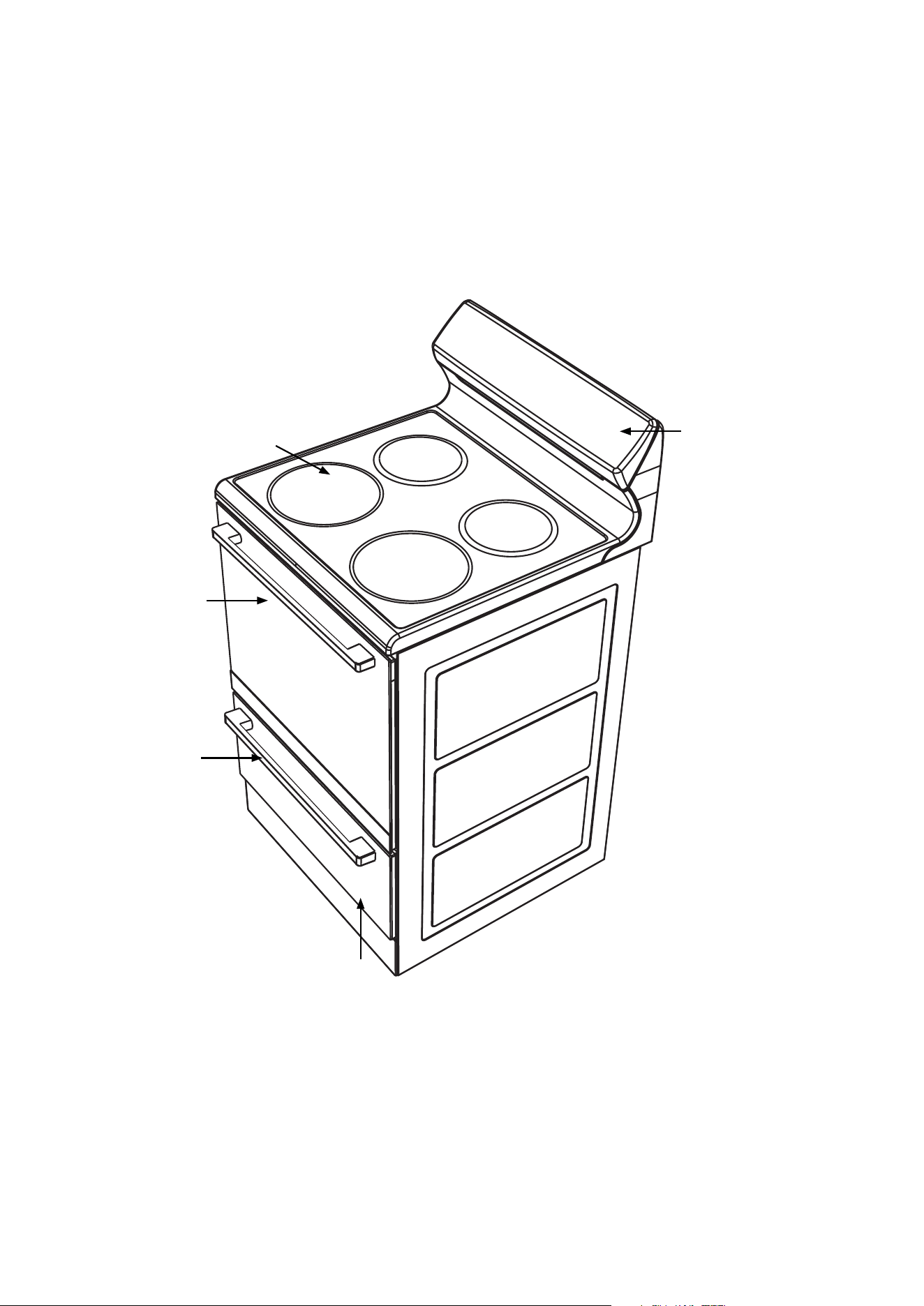
Control panel
Storage drawer
(where fitted)
Kick panel
Hotplate
Oven door
Loading ...
Loading ...
Loading ...