1
ITEM #1279103
Questions, problems, missing parts?
Before returning to your retailer, call our customer
service department at 1-877-355-3326 or 1-925-820-8478, 9 a.m. - 4 p.m., EST, Monday -
Friday. Email: [email protected]
MODEL#F18-I-008-018C
Español p. 20
ATTACH YOUR RECEIPT HERE
Serial Number
Purchase Date
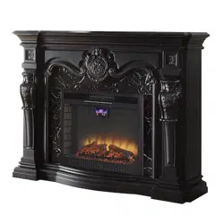
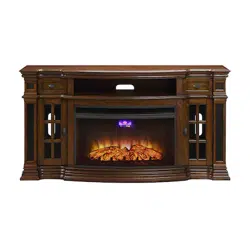
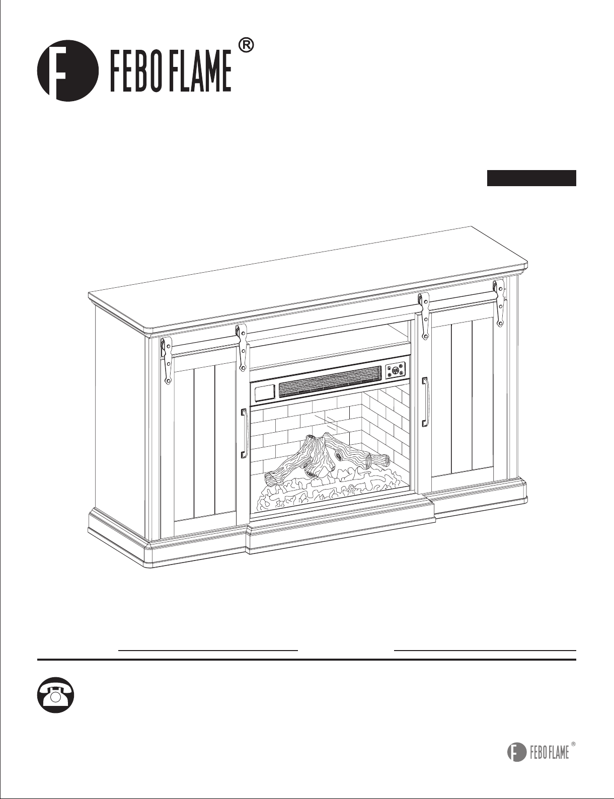
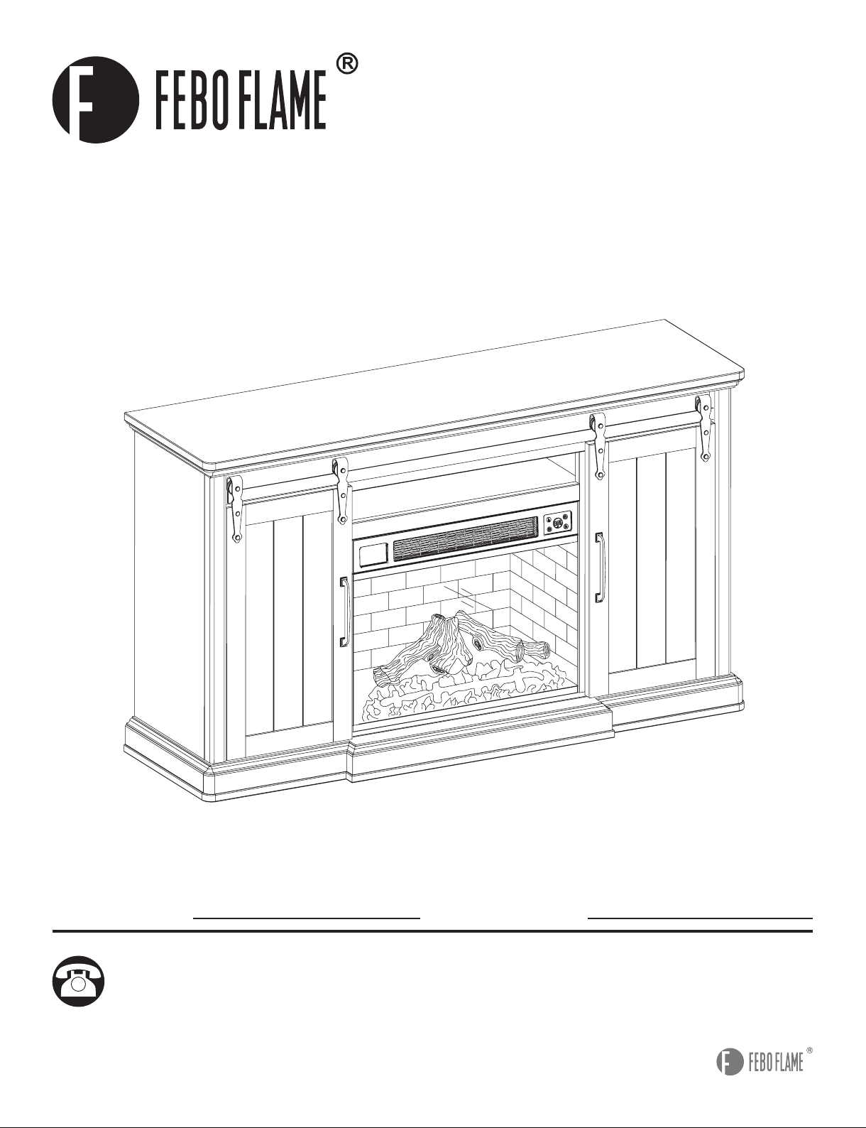
62IN BARN DOOR MANTLE WITH
3D FLAME AND WIFI SMART
ELECTRIC FIREPLACE
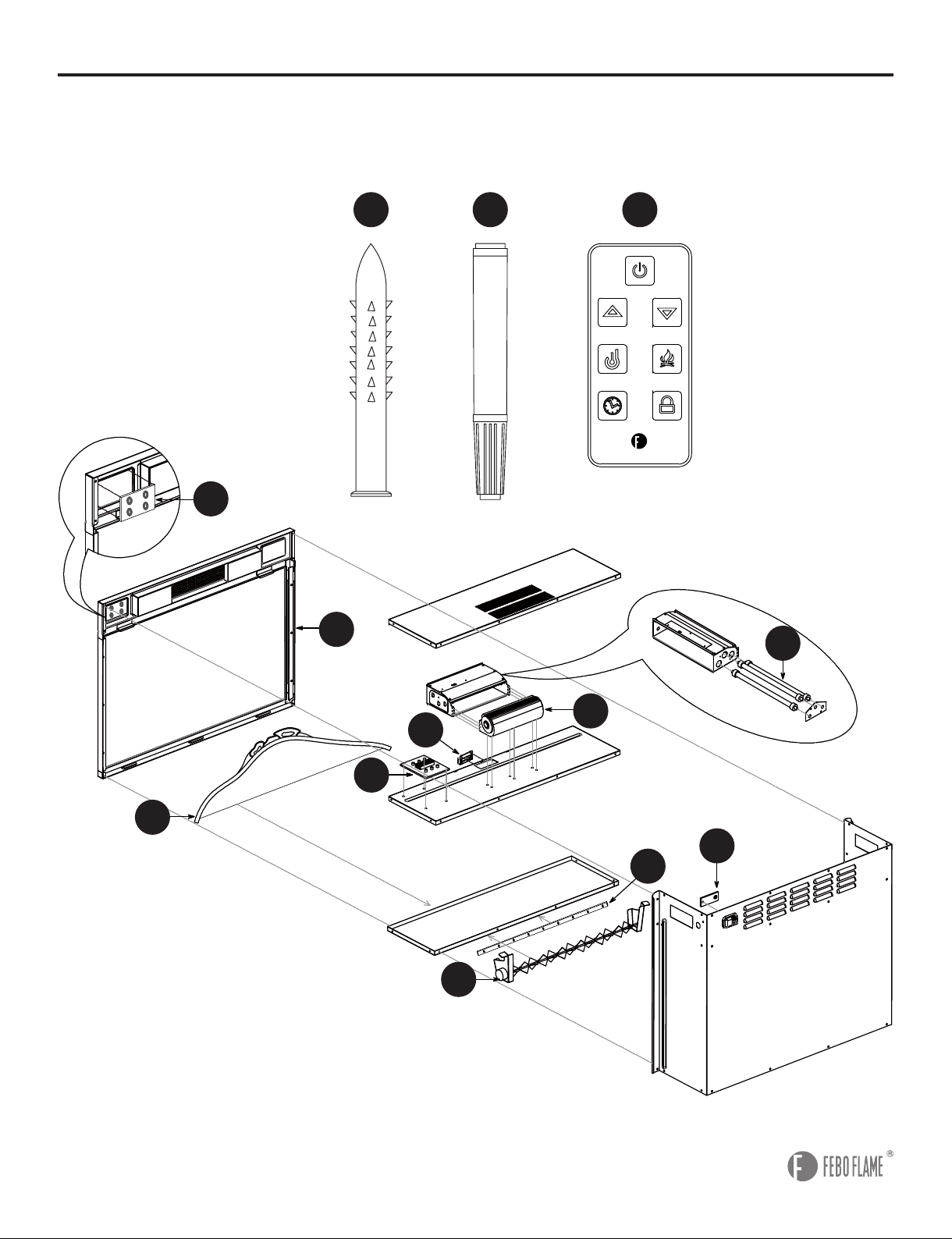
2
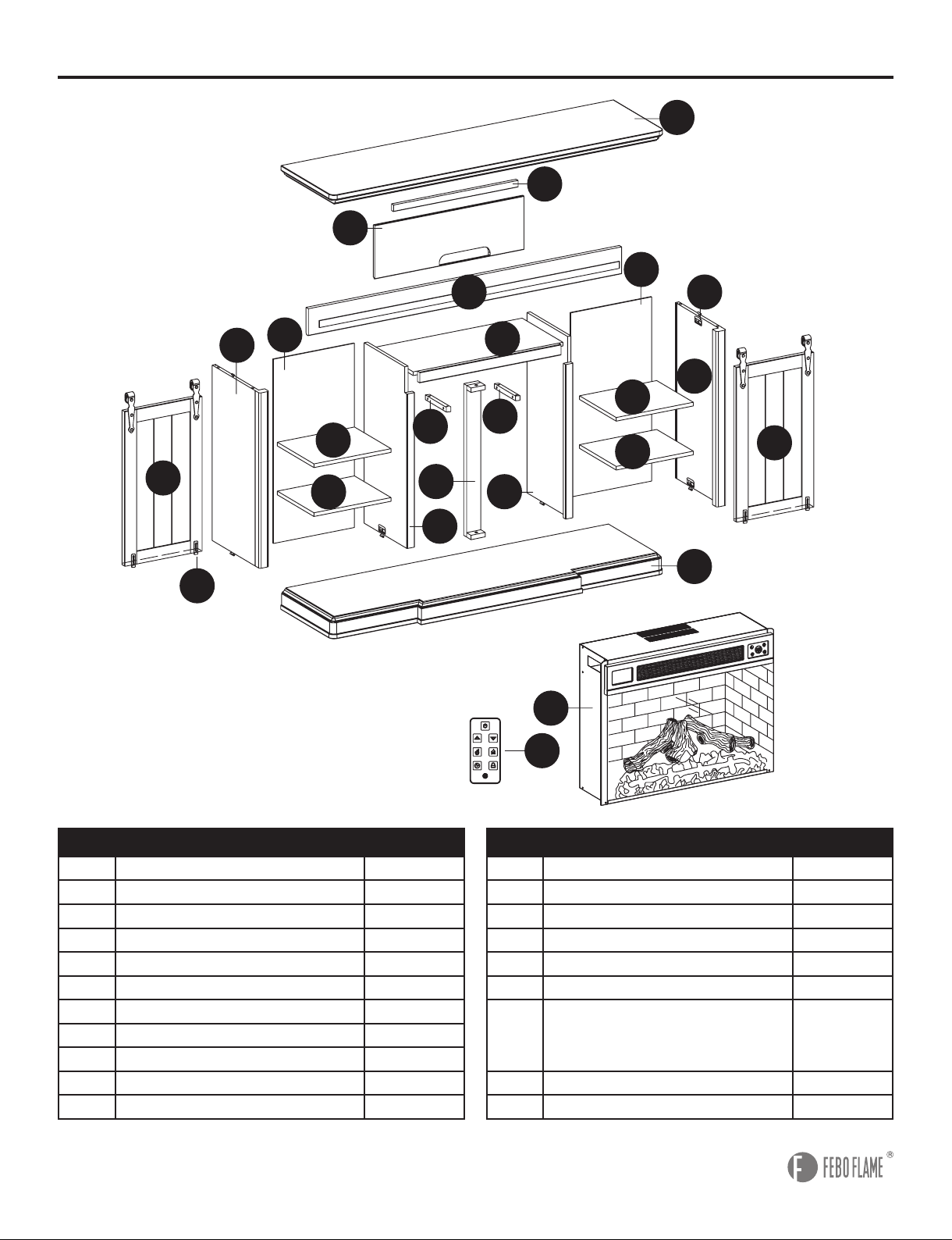
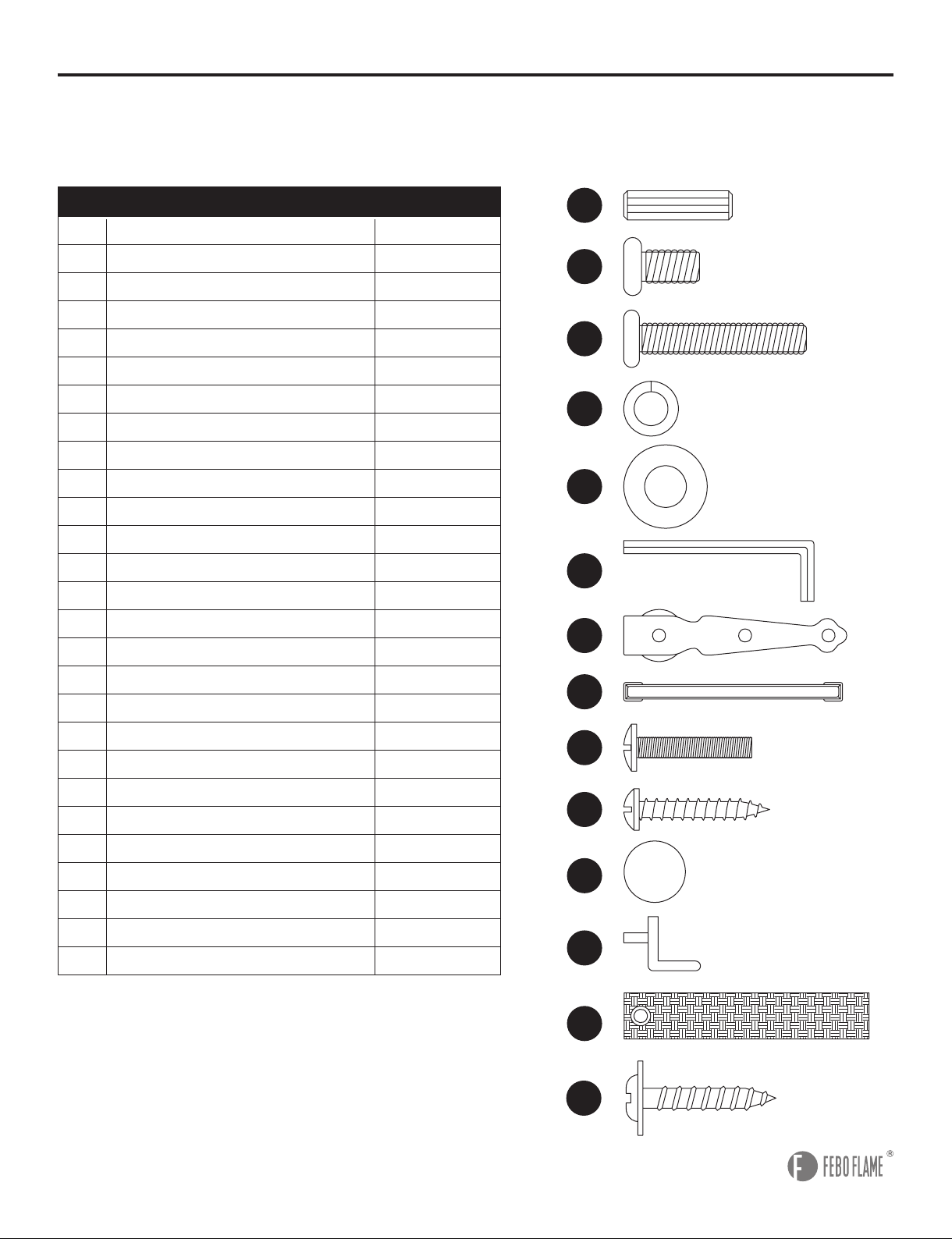
PACKAGE CONTENTS
A
B
C
D
E
F
G
H
I
J
K
L
M
N
O
P
Q
1
2
1
1
1
1
1
1
2
1
1
4
1
1
1
1
1
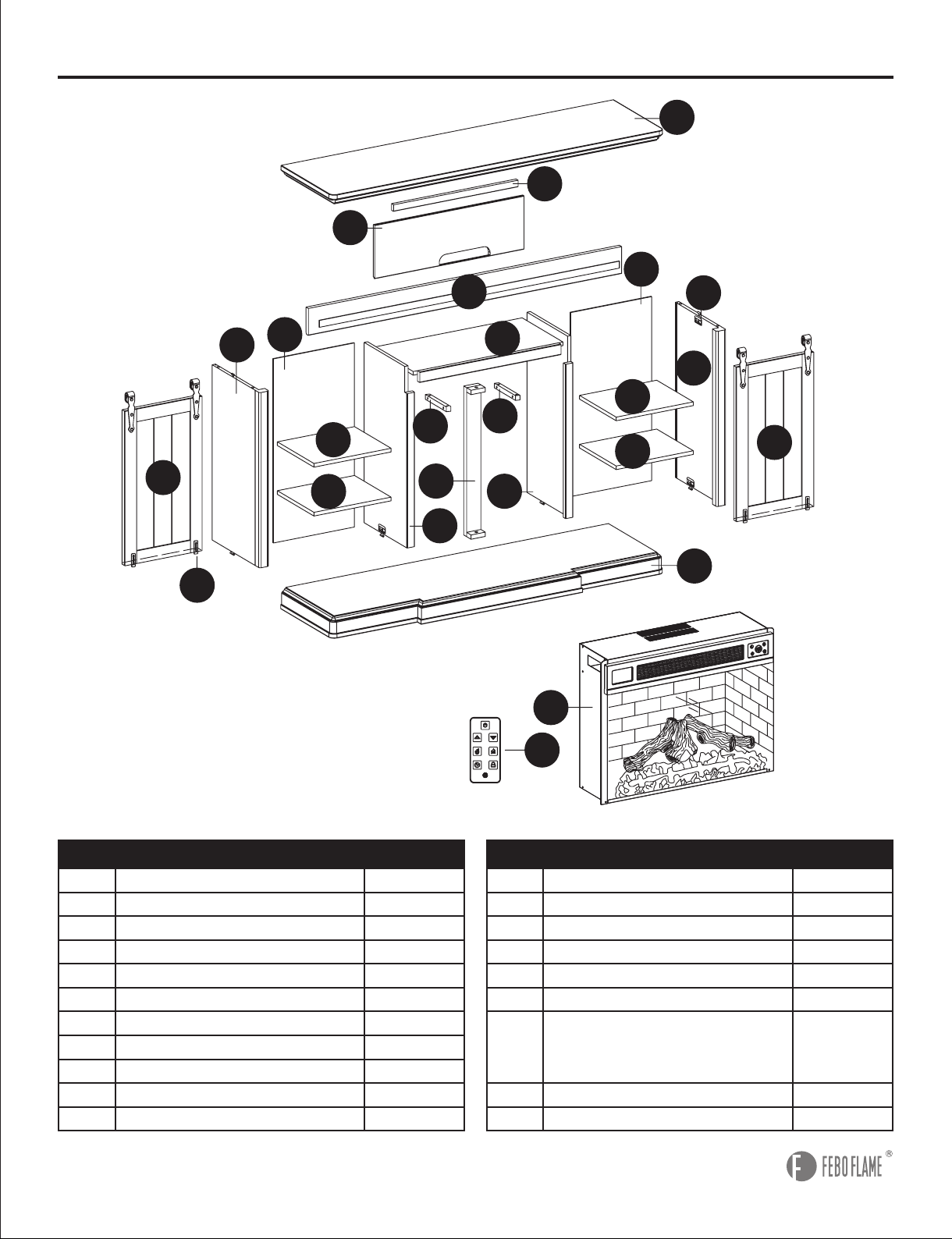
Center Panel
Connecting Wood
Left Middle Panel
Right Middle Panel
Bottom Frame
Left Side Panel
Right Side Panel
Front Rail
Back Panel
Back Rail
Top Frame
Adjustable Shelf
Removable Back Panel
Left Door
Right Door
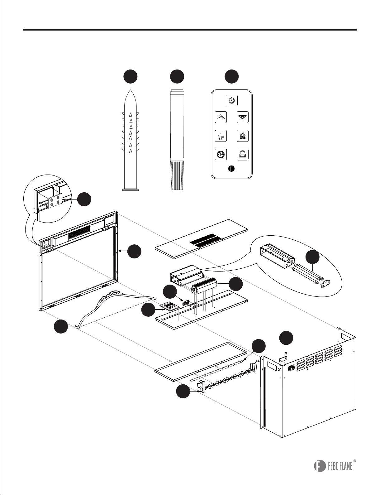
Electric Insert
Remote Control
No-tool Assembly Hardware
PART PARTQUANTITY QUANTITYDESCRIPTION DESCRIPTION
(Preassembled To Left Side Panel (F),
Left Middle Panel (C), Right Middle Panel
(D), Right Side Panel (G))
Glide
(Preassembled To Left Door (N), Right Door (O))
Rear Rail
S
T
4
1
R
8
D
C
T
M
I
I
F
P
Q
E
N
J
K
O
S
R
L
L
L
L
B
B
A
H
G
3
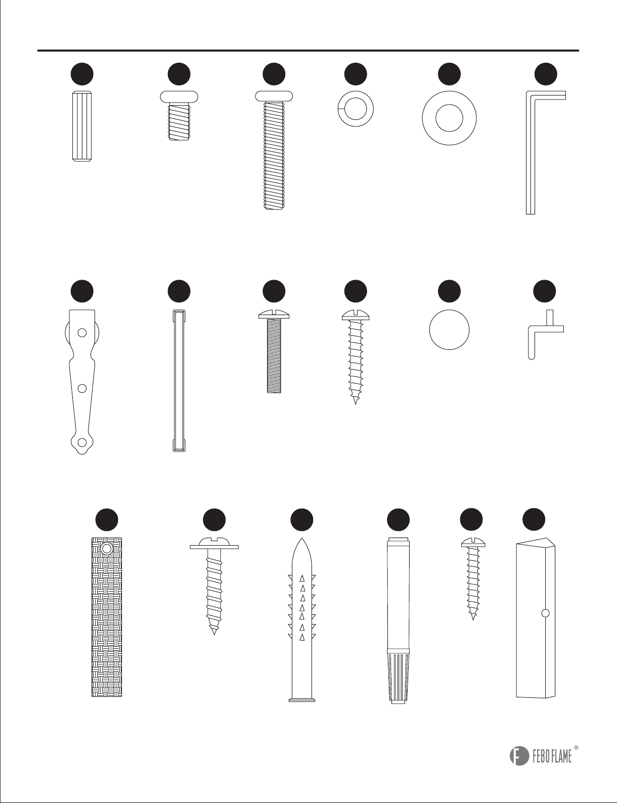
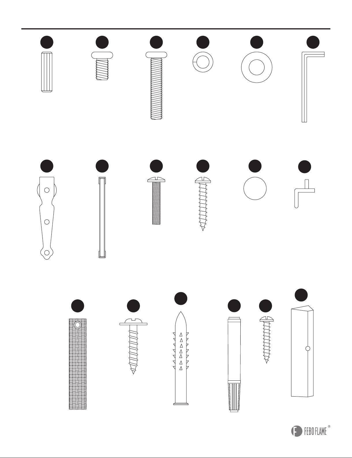
HARDWARE CONTENTS
(not shown actual size)
AA
GG
OO
BB
CC
HH
PP
DD
II
QQ
EE
JJ LL
NN
MM
FF
Wood Dowel
Qty. 24
Sliding Hardware
Qty. 4
Tipping Prevention Device
Qty. 2
Short Hex Bolt
Qty. 8
Long Hex Bolt
Qty. 10
Spring Washer
Qty. 10
Handle Bolt
Qty. 4
Wall Anchor
Qty. 2
Touch-up Pen
Qty. 1
Long Screw
Qty. 5
Handle
Qty. 2
Short Screw
Qty. 4
Flat Washer
Qty. 14
Plastic Pad
Qty. 2
Shelf Pin
Qty. 16
Hex Wrench
Qty. 1
AC AD
Corner Wood
Qty. 8
Screw
Qty. 8

4
SAFETY INFORMATION
Please read and understand this entire manual before attempting to assemble, operate or install the
product. When using electrical appliance, basic precautions should always be followed to reduce the
risk of re, electric shock and injury to persons including the following:
• This appliance is hot when in use. To avoid burns, do not let bare skin touch hot surface. If provided,
use handles when moving this appliance. Keep combustible materials -- such as furniture, pillows,
bedding, papers, clothes and curtains, etc. -- at least 3 feet away from the front of the appliance.
Keep all items away from the sides and rear.
• Extreme caution is necessary when the appliance is used by or near children or invalids and
whenever the appliance is left operating and unattended.
• Always unplug appliance when not in use.
• Do not operate any appliance with a damaged cord or plug or after the appliance malfunctions,
has been dropped or damaged in any manner. Return appliance to authorized service facility for
examination, electrical or mechanical adjustment or repair.
• Do not use outdoors.
• This appliance is not intended for use in bathrooms, laundry areas and similar indoor locations.
Never locate appliance where it may fall into a bathtub or other water container.
• Do not run cord under carpeting. Do not cover the power cord with throw rugs, runners or similar
oor coverings. Arrange cord away from trafc area and where it will not be tripped over.
• To disconnect the appliance, turn all controls “OFF”, then remove the plug from the electrical outlet.
• Connect to properly grounded outlets only.
• Do not insert or allow foreign objects to enter any ventilation or exhaust openings as this may cause
an electric shock or re, or damage the appliance.
• To prevent a possible re, do not block air intakes or exhausts in any manner. Do not use on soft
surfaces, like a bed, where openings may become blocked.
• All electrical appliances have hot and arching or sparking parts inside. Do not use in areas where
gasoline, paint or ammable liquids are used or stored.
• Use this appliance only as described in this manual. Any other use not recommended by the
manufacturer may cause re, electric shock or injury to persons.
• Avoid the use of an extension cord as it may overheat and cause a risk of re. However, if an
extension cord MUST be used, the cord must be No. 14AWG minimum size and rated not less than
1875 watts. The extension cord must be a 3-prong cord with grounding type plug and cord
connection and should not exceed 20 feet in length.
• When transporting or storing the appliance, take care to keep both the unit and power cord/plug dry,
free from excessive vibration and away from heat sources.
• Do not attempt to burn wood or other materials in this appliance.
• This appliance, when installed must be electrically grounded in accordance with the current CSA
C22.1 Canadian Electrical codes or for USA installations, follow local codes and the National
Electric Code, ANSI/NFPA NO.70.
• This unit should be operate under supervision and should not be left on without supervision.
• It is strongly recommended that to use the entire 15 amp outlet for the electric replace only.
• Sharing the outlet with another electronic item could create overload and damage the outlet and
electric items in the long term.
SAVE THESE INSTRUCTIONS

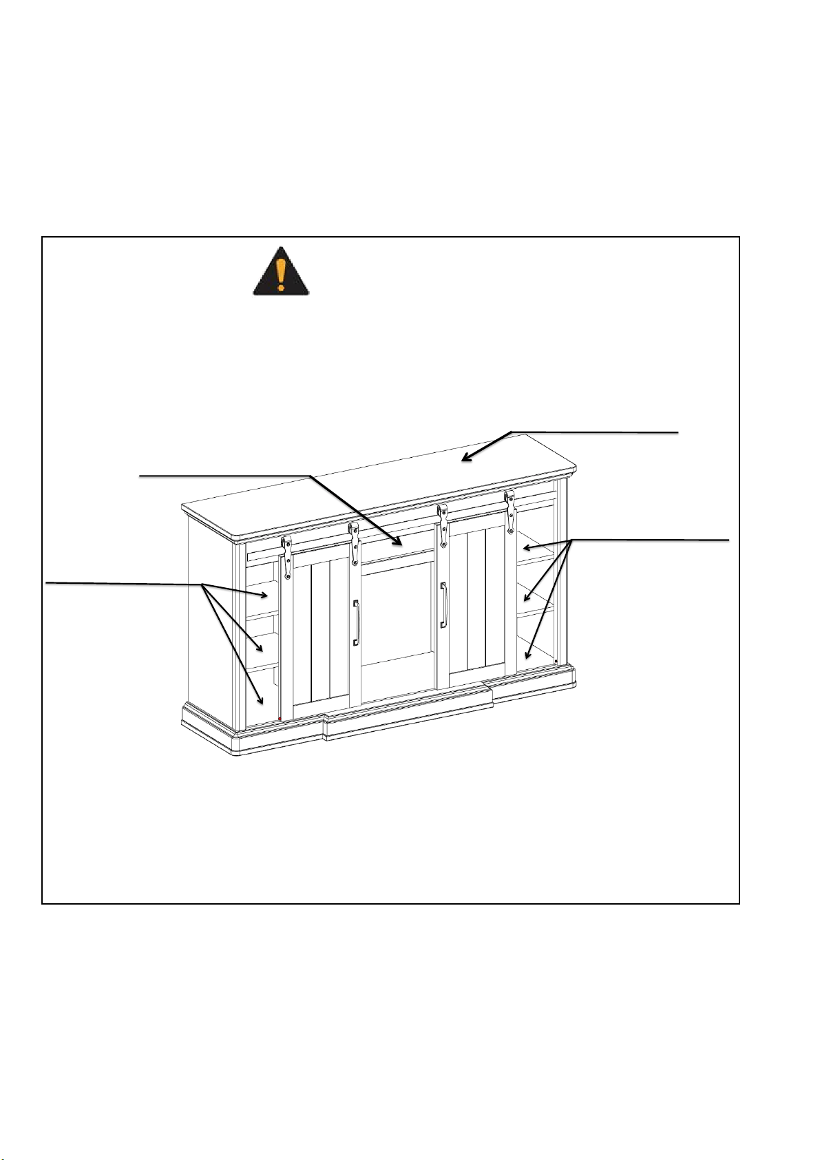
5
CAUTION
Two people are required to lift this item. It is heavy and will break if dropped.
WARNING
• Do not fully tighten the bolts on the assembly until mantel is completed. Positioning of the mantel
pieces during assembly will be easier if there is some exibility between the different pieces. Tighten
all bolts after the assembly is complete and before the insert is set inside.
• Do not use this replace in wet or moist locations.
• To reduce the risk of re, electric shock or injury to persons, disconnect and unplug the power
cord and let cool for at least 10 minutes before attempting any maintenance, cleaning or service for
the electric insert. Only a qualied professional should attempt to service or repair the appliance.
• Do not dispose of batteries of remote control in re. Improper disposal may cause batteries to leak
or explode.
• The preassembled battery in the remote control is not rechargeable; do not recharge the battery.
• Remove the batteries from remote control once they have expired.
• Be sure to insert the battery with the correct polarity.
• Do not ingest the battery; keep the battery away from babies and children.
PREPARATION
Before beginning assembly of product, make sure all parts are present. Compare parts with
package contents list and hardware contents list. If any part is missing or damaged, do not
attempt to assemble the product.
Estimated Assembly Time
: 30 minutes
Tools Required for Assembly (not included): Phillips Screwdriver
Warning:
Changes or modications to this unit not expressly approved by the party responsible for
compliance could void the user’s authority to operate the equipment.
NOTE:
This equipment has been tested and found to comply with the limits for a Class B digital
device, pursuant to Part 15 of the FCC Rules. These limits are designed to provide reasonable
protection against harmful interference in a residential installation. This equipment generates,
uses and can radiate radio frequency energy and, if not installed and used in accordance with the
instructions, may cause harmful interference to radio communications.
However, there is no guarantee that interference will not occur in a particular installation. If this
equipment does cause harmful interference to radio or television reception, which can be determined
by turning the equipment off and on, the user is encouraged to try to correct the interference by one
or more of the following measures:
• Reorient or relocate the receiving antenna.
• Increase the separation between the equipment and receiver.
• Connect the equipment into an outlet on a circuit different from that to which the receiver is connected.
• Consult the dealer or an experienced radio/TV technician for help.
6
ASSEMBLY INSTRUCTIONS
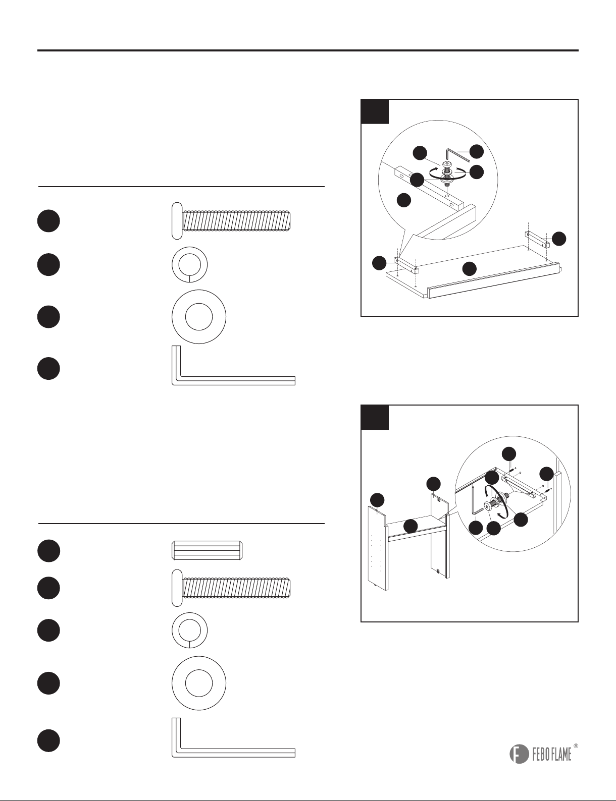
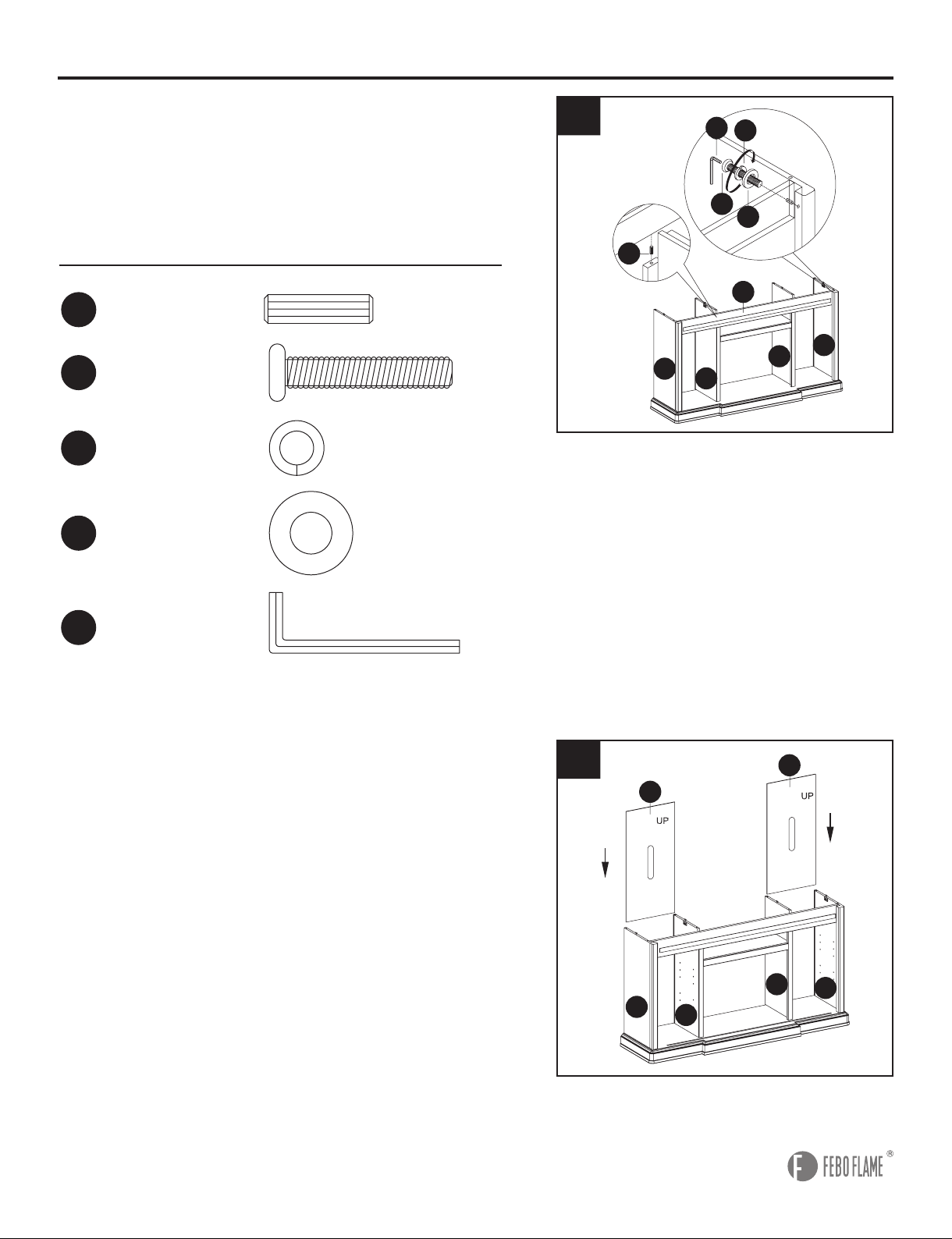
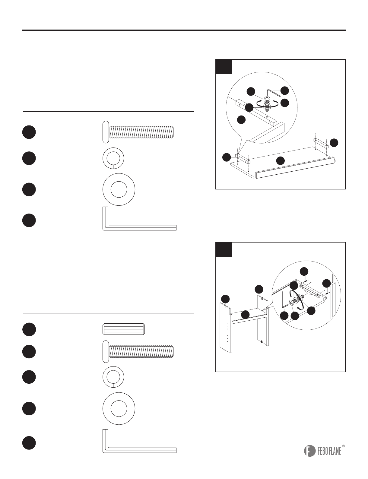
1
1. Attach connecting wood (B) to each side of center
panel (A) using long hex bolt (CC), spring washer
(DD) and at washer (EE). Tighten with Hex wrench
(FF).
2. Insert wood dowels (AA) into each side of center
panel (A). Line up holes on left middle panel (C) and
right middle panel (D) with wood dowels (AA) and
attach to center panel (A) using long hex bolt (CC),
spring washer (DD) and flat washer (EE). Tighten
with hex wrench (FF).
Hardware Used
Hardware Used
AA
DD
DD
CC
CC
EE
EE
FF
FF
Wood Dowel
Spring Washer
Spring Washer
Long Hex Bolt
Long Hex Bolt
Flat Washer
Flat Washer
Hex Wrench
Hex Wrench
x 4
x 4
x 4
x 4
x 4
x 4
x 4
x 1
x 1
Note:
Do not fully tighten the bolts on the assembly until mantel is completed. Assemble the item as
close to its nal location as possible.
2
EE
FF
CC
DD
A
A
B
B
EE
FF
AA
AA
CC
DD
C
D
A
7
AA
AA
Wood Dowel
Wood Dowel
x 4
x4
ASSEMBLY INSTRUCTIONS
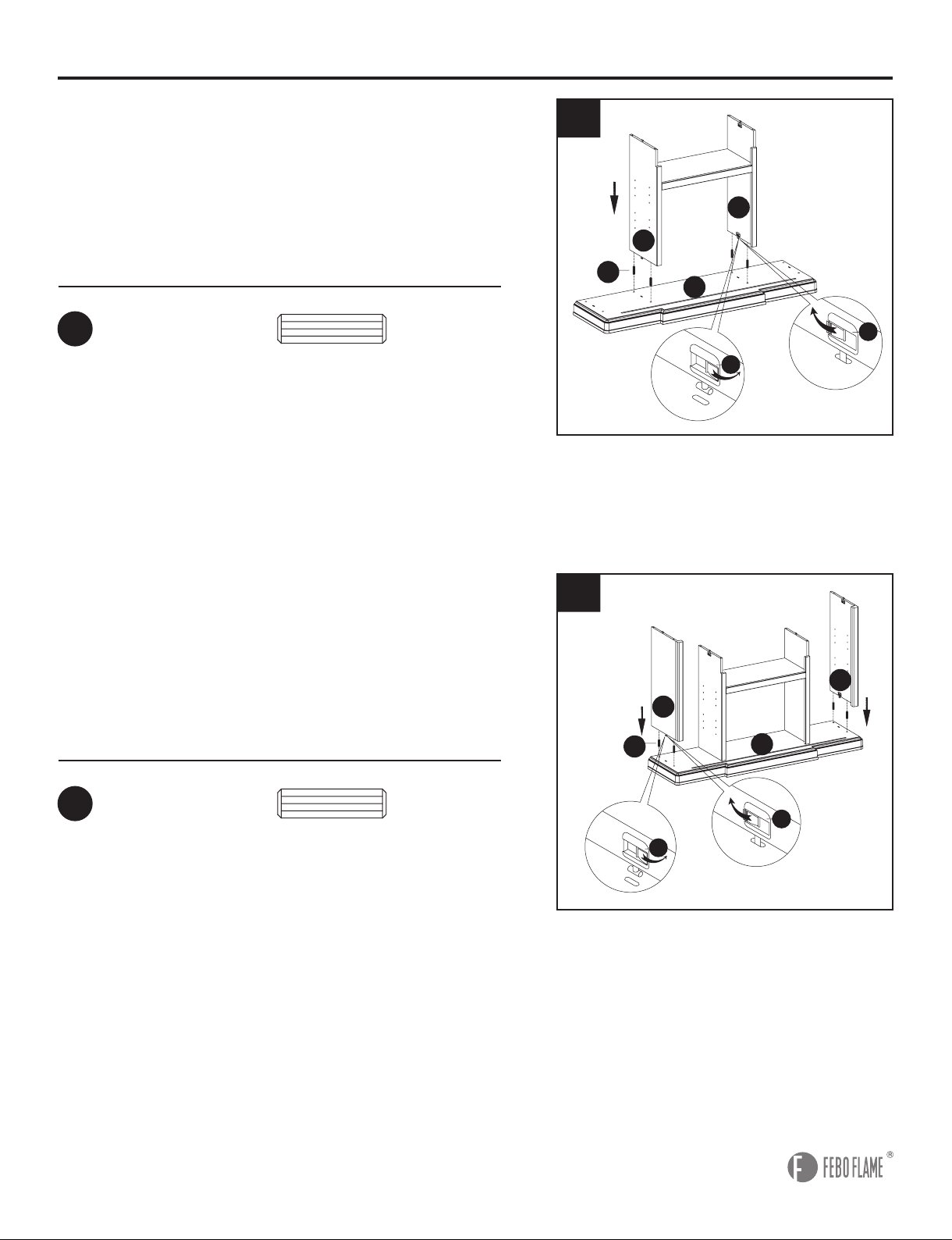
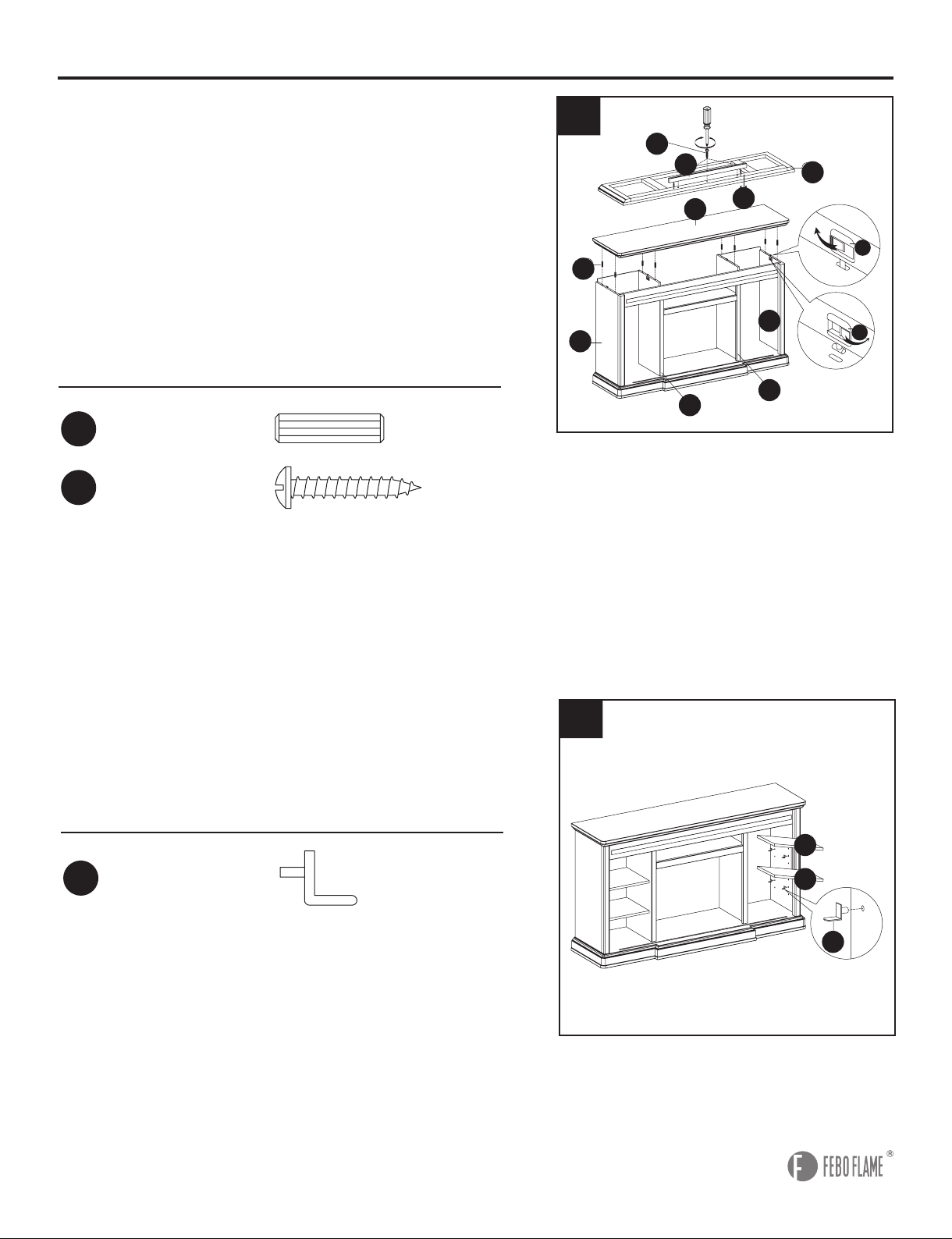
4
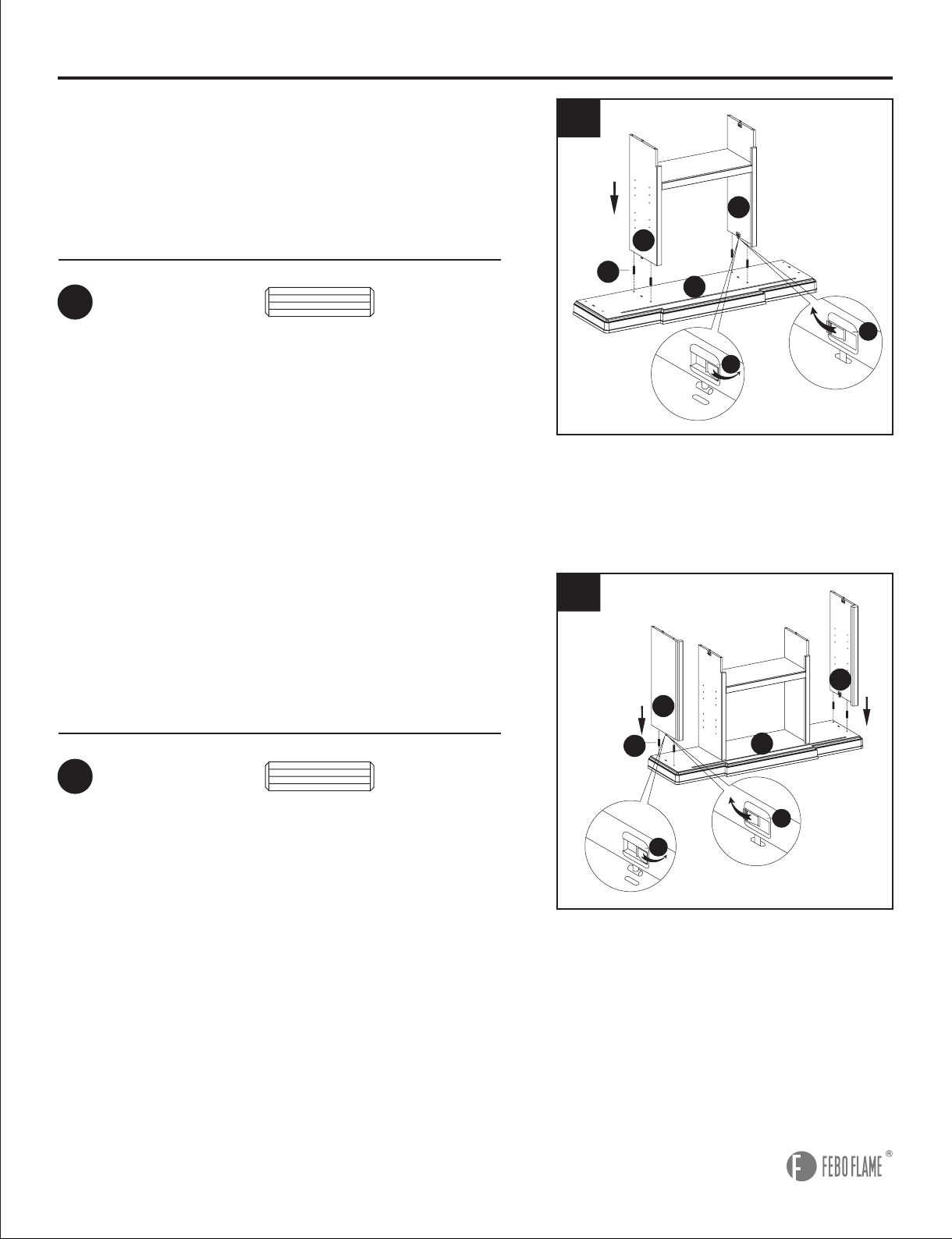
3
4. Insert wood dowels (AA) into bottom frame
(E). Line up holes on left side panel (F) and right
side panel (G) with wood dowels (AA) and attach
to bottom frame (E) by closing no-tool assembly
hardware (R).
3. Insert wood dowels (AA) into bottom frame (E).
Line up holes on left middle panel (C) and right
middle panel (D) with wood dowels (AA) and attach
to bottom frame (E) by closing no-tool assembly
hardware(R).
Hardware Used
Hardware Used
AA
E
F
G
R
R
R
R
Open
Closed
AA
E
F
G
AA
D
C
E
R
R
R
R
Open
Closed
AA
C
D
E
8
ASSEMBLY INSTRUCTIONS
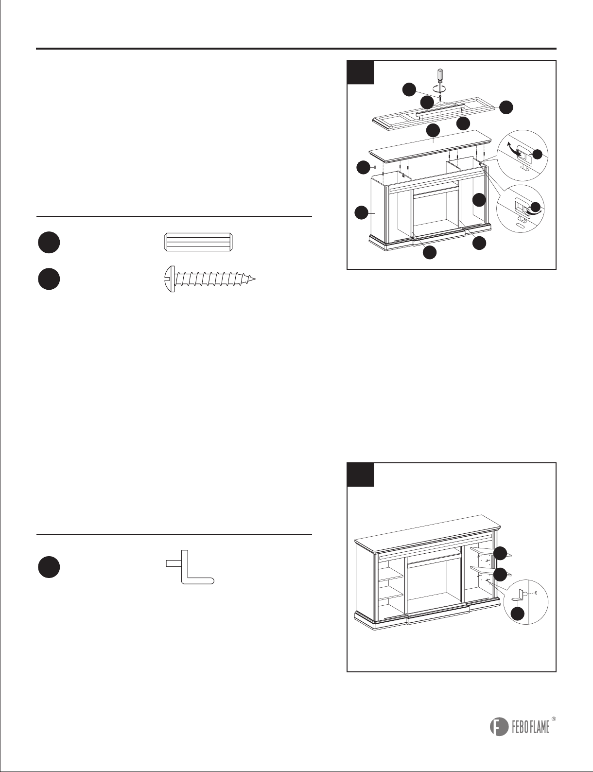
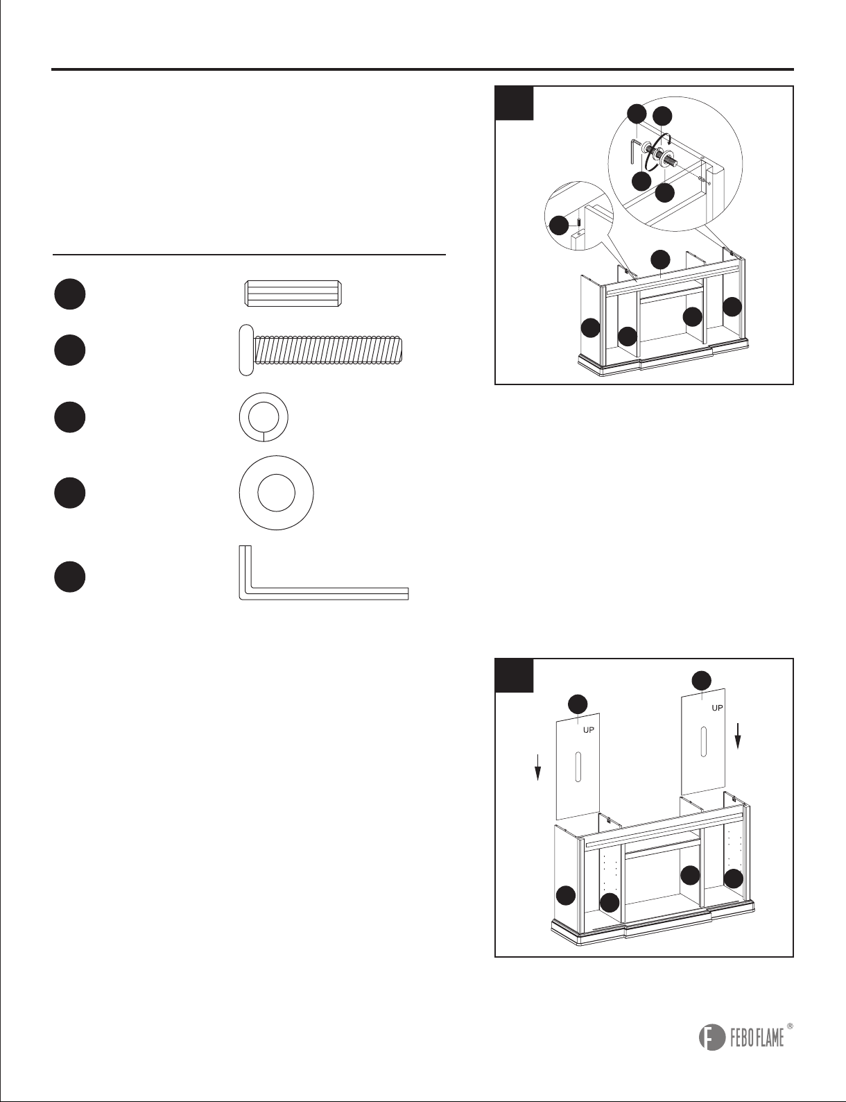
6
6. Insert one back panel (I) down along the groove of
left side panel (F) and left middle panel (C) and the
other back panel (I) down along the groove of right
side panel (G) and right middle panel (D).
5. Insert wood dowels (AA) into left middle panel (C)
and right middle panel (D). Line up holes on front
rail (H) with wood dowels (AA) and attach to left side
panel (F) and right side panel (G) using long hex
bolt (CC), spring washer (DD) and at washer (EE).
Tighten with hex wrench (FF).
Hardware Used
5
EE
CC
FF
AA
DD
H
G
F
I
F
G
I
D
C
I
I
D
F
G
C
DD
CC
EE
FF
Spring Washer
Long Hex Bolt
Flat Washer
Hex Wrench
x 2
x 2
x 2
x 1
AA
Wood Dowel x 2
C
D
9
Hardware Used
ASSEMBLY INSTRUCTIONS
8
7. Attach back rail (J) to top frame (K) with wood
dowels (AA) and long screw (JJ). Tighten with Philips
screwdriver.
Insert wood dowels (AA) into left side panel (F), left
middle panel (C), right middle panel (D) and right
side panel (G). Set top frame (K) over left side panel
(F), left middle panel (C), right middle panel (D)
and right side panel (G). Secure by closing no-tool
assembly hardware (R).
8. Install shelf pins (MM) and insert adjustable
shelves (L) into desired locations in cabinets of
mantel.
Hardware Used
7
L
L
KK
MM
L
L
AA
JJ
MM
Wood Dowel
Long Screw
Shelf Pin
x 10
x 3
x 16
R
R
Open
Closed
Front
Back
AA
AA
JJ
J
J
J
D
J
F
J
C
K
K
G
10
ASSEMBLY INSTRUCTIONS
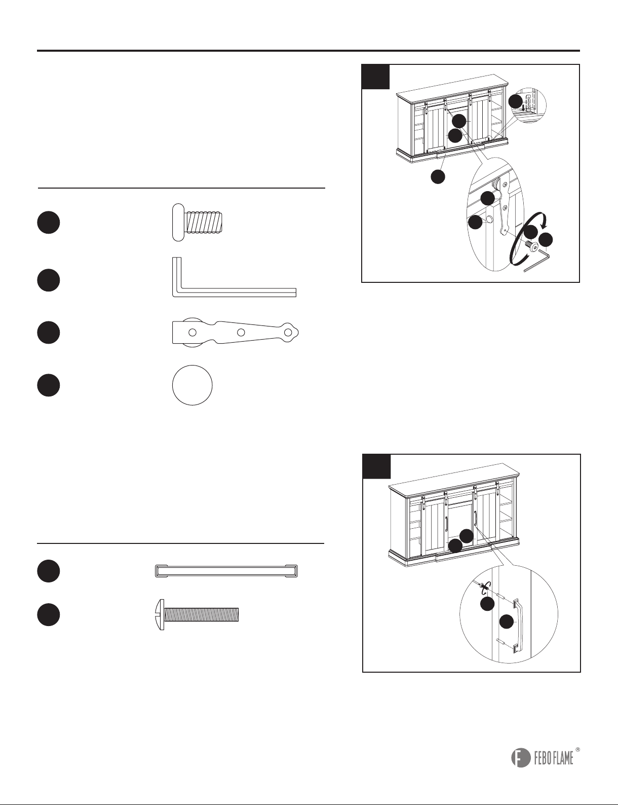
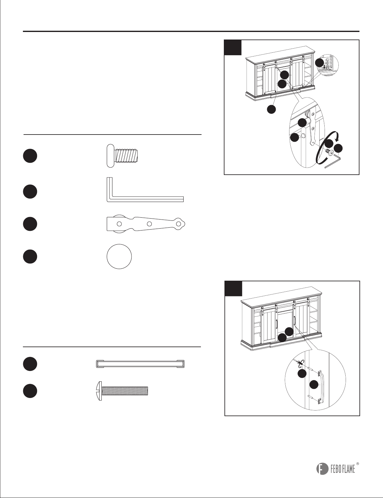
9. Insert the glides (S) into the groove on bottom
frame (E). Hang sliding hardware (GG) on the metal
rail so the wheel rolls smoothly. Align the holes in
sliding hardware (GG) with the holes in the door and
attach sliding hardware (GG) to the door with short
hex bolt (BB). Tighten with hex wrench (FF). Attach
the plastic pad (LL) to left door (N) and right door (O).
Hardware Used
GG
LL
Sliding Hardware
Plastic Pad
x 4
x 2
BB
Short Hex Bolt
x 8
FF
Hex Wrench x 1
9
S
FF
LL
GG
BB
N
E
O
10
Hardware Used
HH
II
Handle
Handle Bolt
x 2
x 4
10. Insert handle bolt (II) through backside of left
door (N) and right door (O) and attach handle (HH).
Tighten handle bolt (II) with Phillips screwdriver to
secure handle (HH).
N
O
I I
HH
11
ASSEMBLY INSTRUCTIONS
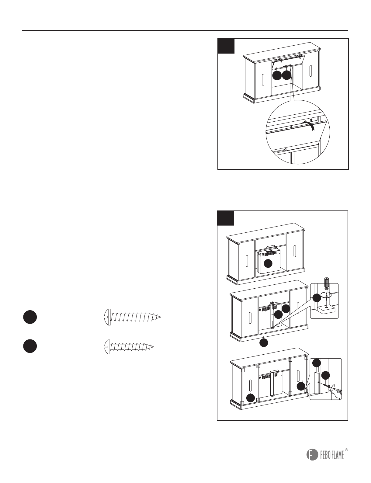
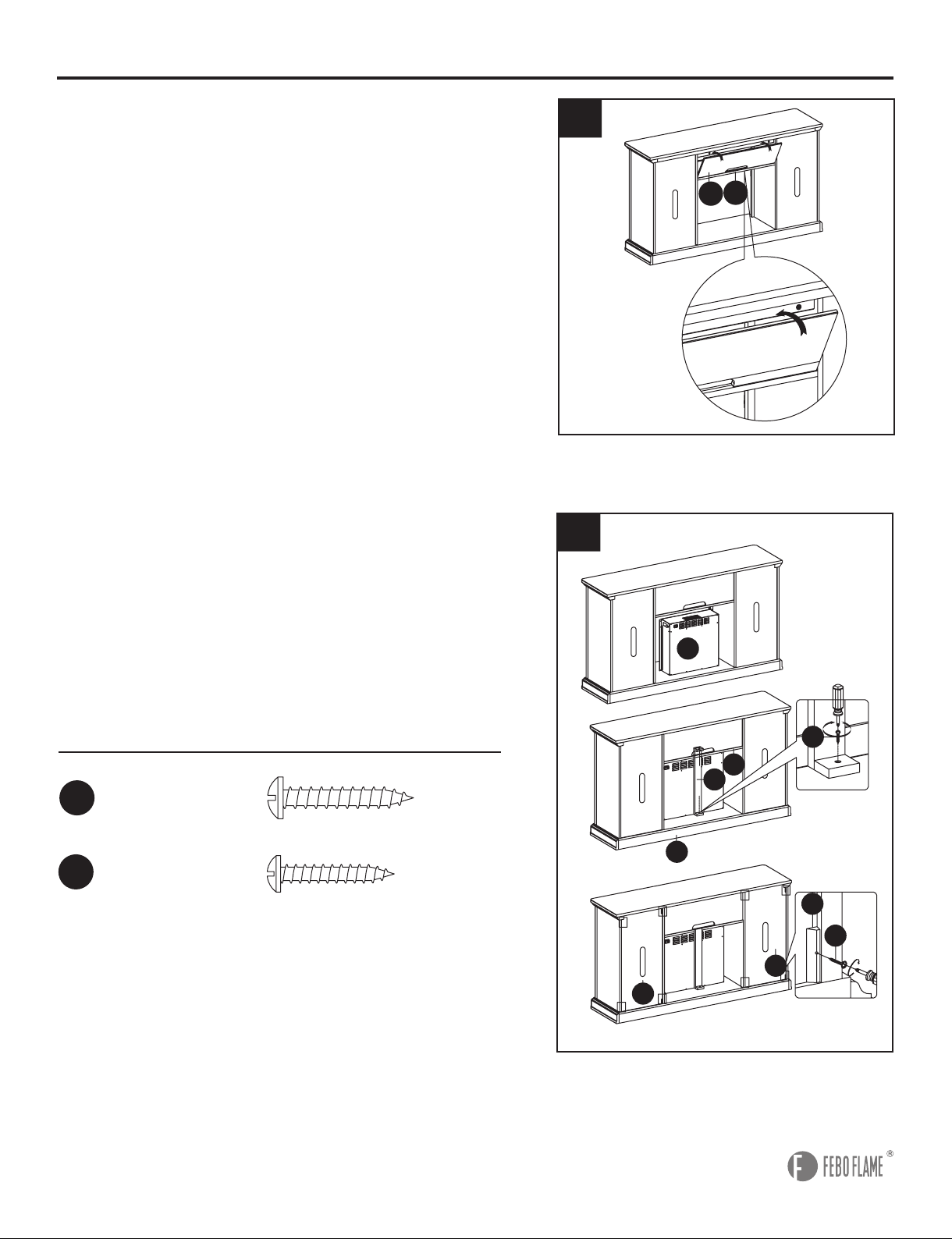
11. From backside of mantel assembly, attach
removable back panel (M) into groove on center
panel (A).
11
M
A
A
12
12. Still from the backside of the assembly, and
with the assistance of another person, insert the
electric insert (P) into the opening. Then, attach
rear rail (T) to bottom center panel (A) and bottom
frame (E) using long screw (JJ). Tighten with Phillips
screwdriver. Then, attach corner wood (AD) to corner
back panel (I) using screws (AC). Tighten with Philips
screwdriver.
Hardware Used
JJ
AC
Long Screw
Screw
x 2
x 8
P
E
I
I
T
A
JJ
AD
AC
12
ASSEMBLY INSTRUCTIONS
13
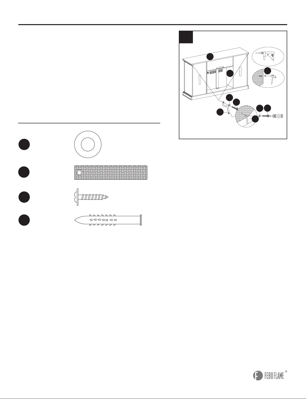
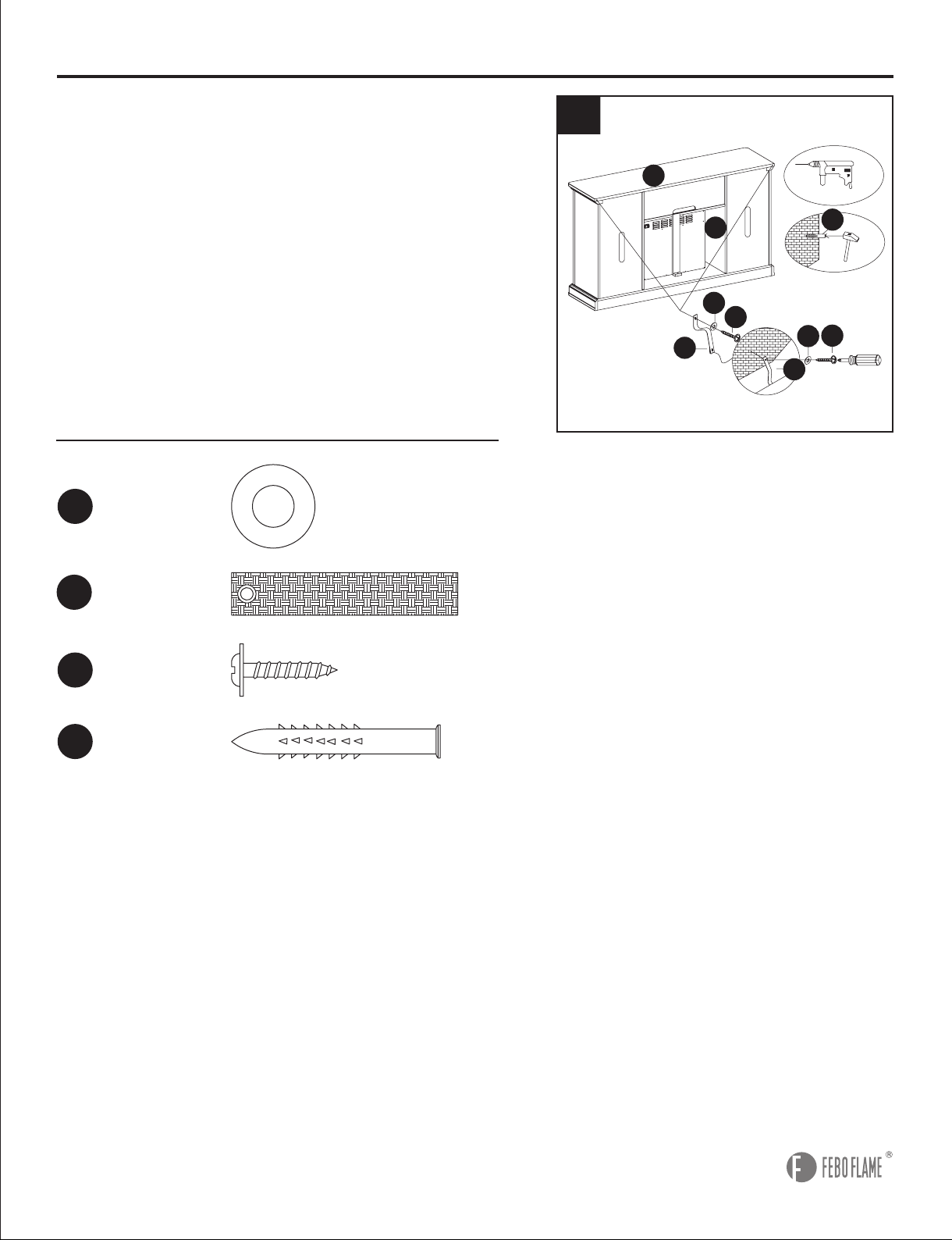
13. Attach the tipping prevention device (NN) to the
back top frame (K) with flat washer (EE) and short
screw (OO). Tighten with Philips Screwdriver. Place
the mantel in the desired location and mark the wall
behind the tipping prevention device (NN). Remove
the mantel and drill a hole for the wall anchor (PP)
at the marked location. Insert the wall anchor (PP)
into the wall. Replace the mantel back into position
and secure the tipping prevention device (NN) with
at washer (EE) and short screw (OO). Tighten with
Philips Screwdriver.
Hardware Used
OO
PP
Short Screw
Wall Anchor
Tipping
Prevention
Device
x 4
x 2
x 2
C
K
PP
EE
EE
NN
NN
OO
OO
NOT INCLUDED
NOT INCLUDED
WALL
WALL
EE
Flat Washer x 4
NN

13
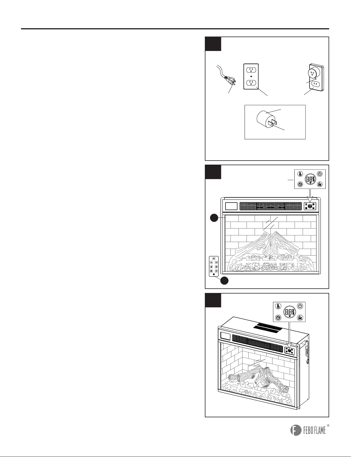
Grounding Pin
Grounding
Means
Adapter
Matel Screw
Cover of Grounding
Outlet Box
1
1. Ensure all controls are in the “OFF” position before
plugging the appliance into a properly grounded
electrical outlet. This appliance is for use on 120 volts.
The appliance has a 3-prong grounded plug. If your
electrical outlet has only 2 slots, you will have to use
an adapter to convert from the 3-prong power cord to a
2-slot receptacle. The green grounding plug extending
from the adapter must be securely connected to a
permanent ground such as a properly grounded outlet
box. The adapter should only be used if a proper 3-slot
receptacle is not available.
Note:
Adapters are not allowed for use in Canada.
2. A-15-amp circuit is required to operate this appliance.
If the breaker trips when the appliance is running, you
may need to move the appliance to another location or
unplug other appliances that are on the same circuit.
The replace control functions can be accessed in three
ways: Using the control panel, located in the upper
right-hand corner of the electric insert (P), or using the
remote control (Q), or using the APP.
3. If the appliance is on, you press any button (except
POWER) on the control panel or on the remote
control (Q), the digital display screen will show the
corresponding numbers of ame, heat or timer. Without
any further operation, the digital display screen will
show room temperature after 15 seconds. Then there is
no display after 5 more seconds.
Note:
For safety, the appliance will automatically turn
off when the doors are closed or barrier influence in
front of the appliance.
OPERATING INSTRUCTIONS
3
P
2
Control Panel
Q
14
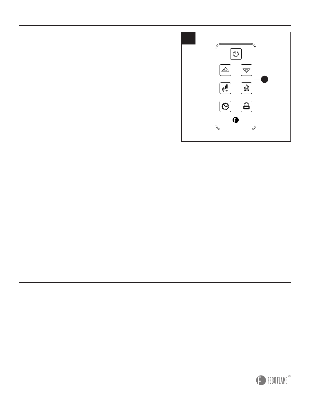
4
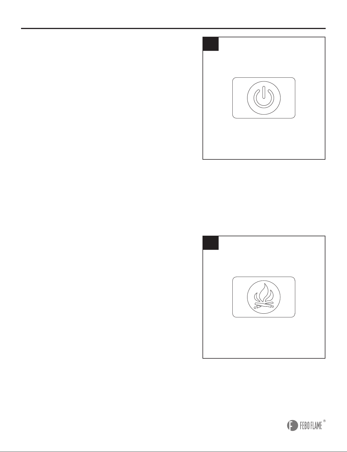
4.
Power:
Push button to turn on or turn off. If ON, the
digital display screen will show the room temperature,
the ame is on. If OFF, all functions except Timer will be
restored at the next power ON.
Note:
Unplugging the unit will reset all functions.
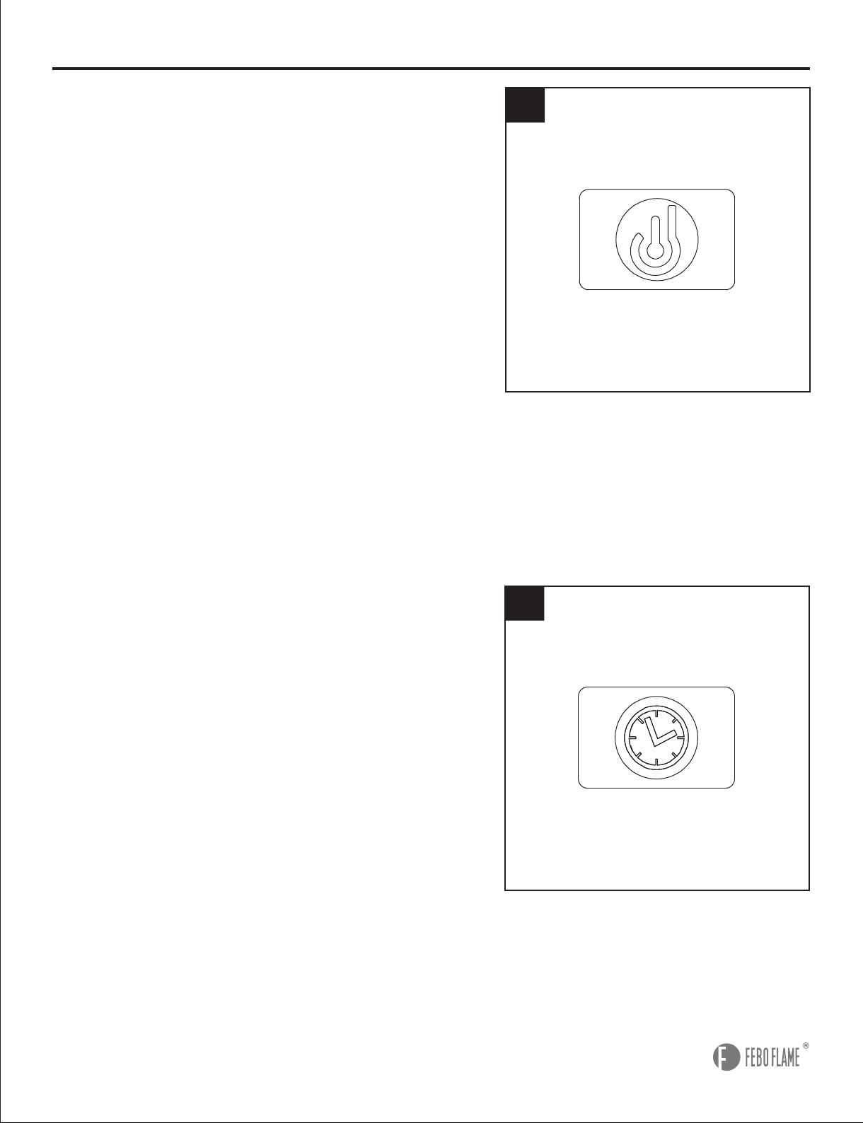
5.
Flame:
Press to activate the flame function. The
FLAME button controls the flame and ember effect.
When the replace is rst turned on, the default state is
amber ame. When you press Flame button continually,
there are 5 selections you can cycle through, including
Amber, Midnight, Polar, Hearth (Flame OFF, the ember
remains on) and Violet, the digital display screen will
show corresponding letter of flame as A, M, P, H, U.
Note:
Press UP or DOWN button on the remote control
to adjust the brightness of flame except Polar mode.
There are 5 levels of the brightness, the digital display
screen will show the corresponding numbers.
Note:
Press and hold the FLAME button for 5 seconds
to activate the child lock function. When the CHILD
LOCK is on, all the other features are disabled, and
the digital display screen will show--. Press and hold
the FLAME button again for 5 seconds to unlock the
function.
OPERATING INSTRUCTIONS
5
15
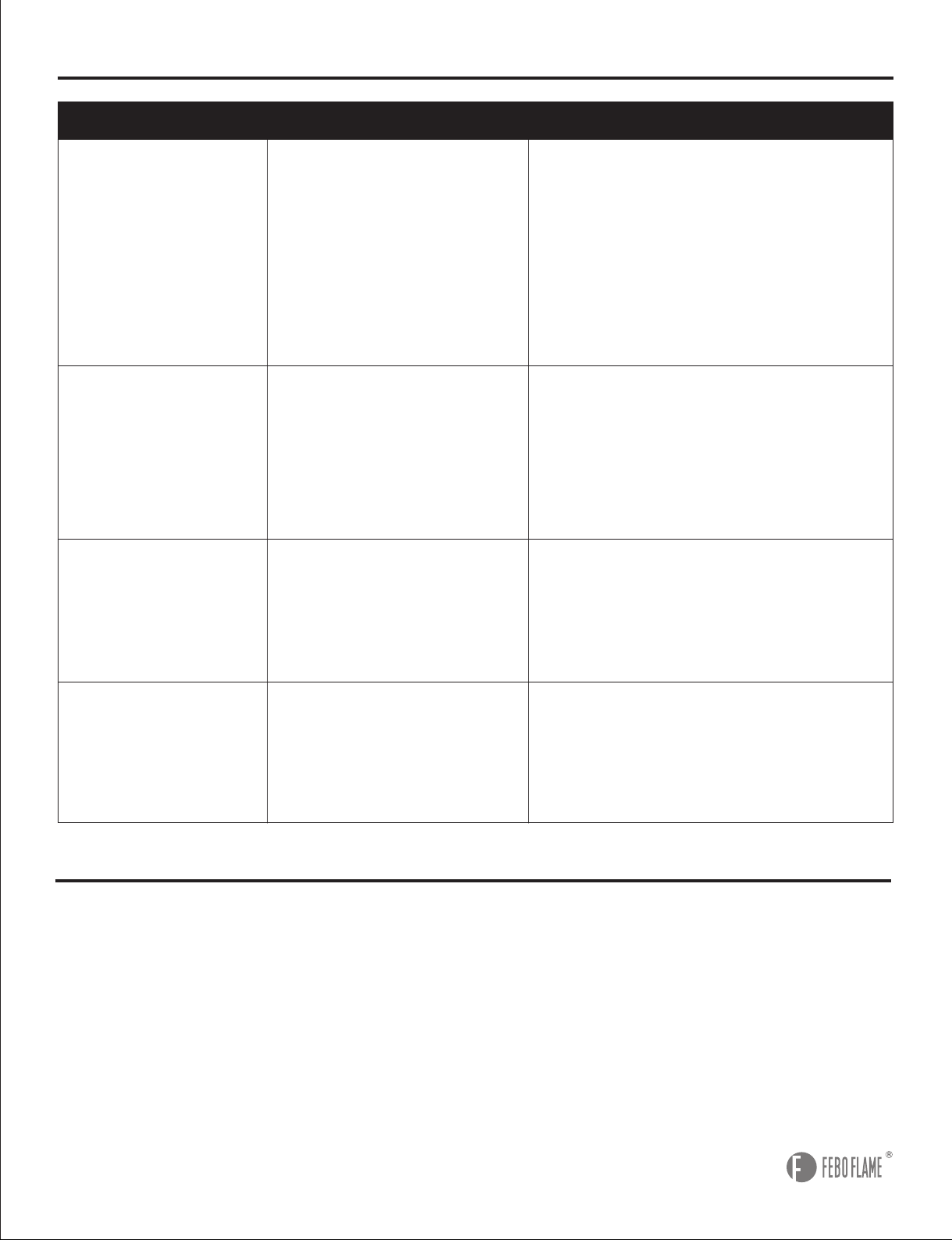
7.
Timer:
Press and hold the button for 1.5 seconds
to activate or deactivate the timer function. The default
state is 0.5 hour. Press the Timer button continually on
the control panel, or press UP or DOWN button on the
remote control to adjust the timer. The choices are 0.5H,
between 1H to 8H with 1H interval. Once the TIMER is
on and the desired setting is reached, the system will
shut down.
OPERATING INSTRUCTIONS
7
6
6.
Heater:
Press and hold the button for 1.5 seconds to
activate or deactivate
the heater function. The system
will start the default temperature setting at 80°F/27°C.
There are 7 adjustable heat levels, ranging from
90°F/32°C to 60°F/16°C. Press the button again to adjust
the heat levels, or press the UP or DOWN button on
the remote control to adjust the levels, noting each level
increases or decreases the temperature by 5°F. When
the heater is on, digital display screen will show the
setting temperature corresponding numbers. And when
this feature is off, the inner blower will continue to run
for additional 1 minutes to cool down the unit in order to
protect the heating elements before the unit completely
shuts off.
Note:
You can switch the temperature display from
Fahrenheit to Celsius by pressing and holding the
HEATER button on the remote control for approximately
3 seconds. Without any further operation, the digital
display screen will show room temperature after 15
seconds. Then there is no display after 5 more seconds.

16
CARE AND MAINTENANCE
• Keep the replace in a climate-controlled environment. Extreme temperature and humidity changes
can cause warping, shrinking and/or splitting of wood.
• Use a clean dry cloth to clean the replace.
• Clean metal surfaces of electric insert with a clean damp cloth, making sure not to push dust or
debris into any air intake or exhaust vents.
• Do not use abrasive cleaners or spray liquids on any part of the appliance.
• Periodic cleaning/vacuuming of the fan/heater unit is strongly recommended to ensure that no dirt
or foreign objects build up.
• Battery Replacement: Use one lithium coin cell battery (size CR2025) for the remote control.
• Use the touch-up pen (QQ) to repair minor scratches and damages on mantel.
OPERATING INSTRUCTIONS
8
8. Buttons on the Remote Control (Q) have the same
functions as those on the Control Panel except Heater
and Timer.
Heater: On the remote control (Q), press this button
immediately activate or deactivate the heater function.
Press the UP or DOWN button to adjust the heat level.
Timer: On the remote control (Q), press this button
immediately activate or deactivate the timer function.
Press the UP or DOWN button to adjust the timer.
Child Lock: Press this button immediately activate or
deactivate the function.
Down: Use to turn down the heat, brightness of ame
or timer. When FLAME / HEATER / TIMER is not
activated, press this button can adjust the brightness of
ame.
Up: Use to turn up the heat, brightness of flame
or timer. When FLAME / HEATER / TIMER is not
activated, press this button can adjust the brightness of
ame.
CAUTION:
The Remote Control (Q) comes preassembled
with a correct battery, but you must remove the insulation
plastic lm from the battery before operation.
Q
17
TROUBLESHOOTING
SOLUTION
PROBLEM
POSSIBLE CAUSE
1. Push ame button to increase light.
2. Contact customer service center.
3. Remove screws holding back panel
in place and remove back panel.
Secure end of “Flame wand” back
into the support bracket.
4. Contact customer service center.
1. Turn all controls off, unplug the
appliance, allow the insert to cool
down for at least 10 minutes, and
then plug in and restart.
2. Reset house circuit breaker.
Turn all controls off, unplug the
appliance, allow the insert to cool down
for at least 10 minutes, and then plug
in and restart.
1. Replace all batteries in the remote
control.
2. Operate the remote at a distance
less than 20 feet from the front of the
appliance; point the remote at the
control panel.
1. Low batteries.
2. Distance.
The overheat protection
device in the appliance
has been triggered.
1. The overheat protection
device in the appliance
has been triggered.
2. House circuit breaker
has been tripped.
1. Dimmer control button
is set too low.
2. LED strip not
functioning.
3. “Flame wand” has come
loose from bracket.
4. “Flame wand” motor is
not functioning.
Simulated ame
effect is dim or not
present.
The appliance
turns off and will
not turn back on.
The appliance does
not turn on when
the button is pushed
to “ON”.
Remote control
does not work.
WARRANTY
The manufacturer warrants this item against defects in materials and workmanship for a period of one
(1) year from the date of original retail purchase. This warranty applies only to the original purchaser.
This warranty does not apply to any damage on the product by accident, misuse, or modified,
improper installation or by afxing accessories not produced by the manufacturer. The manufacturer
is not accountable whatsoever for product installation during the warranty period. There is no further
expressed warranty. The manufacturer shall not be legally responsible for incidental, consequential
or special damages arising at or in connection with product use or performance except as may
otherwise be accorded by law. The manufacturer disclaims any and all implied warranties.
18
REPLACEMENT PARTS LIST
For replacement parts, call our customer service department at 1-877-355-3326 or 1-925-820-8478,
9 a.m. - 4 p.m., EST, Monday - Friday. Email: [email protected]
AA
BB
HH
CC
II
DD
JJ
LL
EE
MM
NN
FF
PART PART #
DESCRIPTION
Q
AA
BB
CC
DD
EE
FF
GG
HH
II
JJ
LL
MM
NN
OO
PP
QQ
RR
SS
TT
UU
VV
WW
XX
YY
ZZ
AB
Remote Control
Wood Dowel
Short Hex Bolt
Long Hex Bolt
Spring Washer
Flat Wahser
Hex Wrench
Sliding Hardware
Handle
Handle Bolt
Long Screw
Plastic Pad
Shelf Pin
Tipping Prevention Device
Short Screw
Wall Anchor
Touch-up Pen
Blower
Quartz Tube
LED Light Board
Wooden Log
Control Panel
Light Sensor
Front Frame
Heater Sensor
Flame Generator Driver Motor
Mother Board
2019-411001
2019-401001
2019-402001
2019-402002
2019-402003
2019-403001
2019-404001
2019-405001
2019-406001
2019-406002
2019-407001
2019-409001
2019-412001
2019-413001
2019-414001
2019-415001
2019-416001
2019-417001
2019-418001
2019-415002
2019-419001
2019-422001
2019-423001
2019-424001
2019-425001
2019-426001
2019-427001
GG
OO
19
REPLACEMENT PARTS LIST
For replacement parts, call our customer service department at 1-877-355-3326 or 1-925-820-8478,
9 a.m. - 4 p.m., EST, Monday - Friday. Email: [email protected]
Q
Printed in Vietnam
VV
XX
YY
ZZ
AB
WW
RR
SS
TT
UU
QQPP
20
ARTÍCULO #1279103
¿Preguntas, problemas, piezas faltantes?
Antes de volver a la tienda, llame al Servicio al
Cliente al 1-877-355-3326 o 1-925-820-8478, de lunes a viernes de 8 a.m. a 8 p.m., hora
estándar del Este. Correo electrónico: [email protected]
MODELO#F18-I-008-018C
ADJUNTE SU RECIBO AQUI
Número de serie
Fecha de compra
REPISA PARA CHIMENEA TIPO
PUERTA DE GRANERO DE
157,48 CM CON LLAMA 3D Y CHIMENEA
ELÉCTRICA INTELIGENTE CON WIFI
21
CONTENIDO DEL PAQUETE
A
B
C
D
E
F
G
H
I
J
K
L
M
N
O
P
Q
1
2
1
1
1
1
1
1
2
1
1
4
1
1
1
1
1
Panel central
Madera de conexión
Panel central izquierdo
Panel central derecho
Estructura inferior
Panel izquierdo
Panel derecho
Riel frontal
Panel posterior
Riel posterior
Estructura superior
Repisa ajustable
Panel posterior desmontable
Puerta izquierda
Puerta derecha
Accesorio eléctrico
Control remotoNo-tool
PIEZA PIEZACANTIDAD CANTIDADDESCRIPCIÓN DESCRIPCIÓN
Aditamentos de ensamblaje que no
necesitan herramientas
(Preensamblados en el panel
lateral izquierdo (F), panel central izquierdo (C), panel central
derecho (D), panel lateral derecho (G))
Deslizador
(Preensamblados en la puerta izquierda (N), puerta derecha (O))
Riel trasero
S
T
4
1
R
8
D
C
T
M
I
I
F
P
Q
E
N
J
K
O
S
R
L
L
L
L
B
B
A
H
G
22
ADITAMENTOS
(no se muestran en tamaño real)
AA
GG
NN
BB
CC
HH
OO
DD
II
PP
EE
JJ
MM
LL
FF
Espiga de
madera
Cant. 24
Aditamentos
deslizantes
Cant. 4
Dispositivo de prevención de vuelcos
Cant. 2
Perno
hexagonal corto
Cant. 8
Perno hexagonal
largo
Cant. 10
Arandela de
resorte
Cant. 10
Perno de
manija
Cant. 4
Ancla de expansión
para pared
Cant. 2
Aplicador de retoque
Cant. 1
Tornillo
largo
Cant. 5
Manija
Cant. 2
Tornillo
corto
Cant. 4
Arandela
plana
Cant. 14
Almohadilla
plástica
Cant. 2
Pasador de
repisa
Cant. 16
Llave
hexagonal
Cant. 1
QQ
AC
AD
Madera esquina
Cant. 8
Tornillo
Cant. 8

23
INFORMACIÓN DE SEGURIDAD
Lea y comprenda completamente este manual antes de intentar ensamblar, usar o instalar el
producto. Cuando utilice electrodomésticos, siempre tome medidas de precaución básicas para
reducir el riesgo de incendios, descargas eléctricas y lesiones personales, incluidas las siguientes:
• Este electrodoméstico se calienta cuando está en funcionamiento. Para evitar quemaduras, no
toque las supercies calientes sin protegerse la piel. Si se incluyen, utilice las manijas para
trasladar el electrodoméstico. Mantenga los materiales inamables, como muebles, almohadas,
ropa de cama, papeles, ropa, cortinas, etc. al menos a 0,91 m de la parte delantera del
electrodoméstico. Mantenga todos los artículos lejos de los costados y la parte posterior.
• Debe tener extrema precaución cuando niños o personas discapacitadas usen el electrodoméstico,
o cuando se use cerca de ellos, y siempre que el electrodoméstico se deje funcionando sin
vigilancia.
• Siempre desenchufe el electrodoméstico cuando no lo use.
• No use ningún electrodoméstico si el cable o enchufe están dañados ni después de que presente
fallas, haya sufrido caídas o algún tipo de daño. Devuelva el electrodoméstico a un local de servicio
autorizado para una revisión, ajuste eléctrico o mecánico, o reparación.
• No lo use en exteriores.
• Este electrodoméstico no se debe usar en el baño, cuartos de lavado ni espacios interiores
similares. Nunca coloque el electrodoméstico donde se pueda caer dentro de una bañera u otro
contenedor de agua.
• No pase el cable por debajo de una alfombra. No cubra el cable eléctrico con alfombras, tapetes o
similares. Coloque el cable lejos de la zona de tránsito en donde nadie se pueda tropezar y caer.
• Para desconectar el electrodoméstico, gire los controles a la posición “OFF” (apagado) y luego
retire el enchufe del tomacorriente.
• Conecte solo a tomacorrientes con la debida puesta a tierra.
• No introduzca objetos extraños ni permita que entren en las aberturas de ventilación o escape, ya
que pueden provocar descargas eléctricas, incendios o daños en el electrodoméstico.
• Para evitar incendios, no bloquee las entradas ni salidas de aire de manera alguna. No use sobre
supercies blandas, como una cama, donde las aberturas se puedan bloquear.
• Todos los electrodomésticos tienen piezas calientes, que forman arcos eléctricos o producen
chispas. No lo use en áreas donde se use o almacene gasolina, pintura o líquidos inamables.
• Utilice este electrodoméstico solo como se describe en este manual. Cualquier otro uso no
recomendado por el fabricante puede causar incendios, descargas eléctricas o lesiones personales.
• Evite utilizar una extensión eléctrica, ya que se puede sobrecalentar y provocar un incendio. Sin
embargo, si TIENE que usar una extensión eléctrica, debe ser de tamaño mínimo AWG No.14 y
tener una clasicación de 1875 vatios como mínimo. La extensión eléctrica debe tener un enchufe
y una conexión con puesta a tierra de 3 clavijas, y su longitud no debe superar los 6,10 m.
• Al transportar o guardar el electrodoméstico, preocúpese de mantener secos el cable eléctrico y el
enchufe, sin vibración excesiva y alejado de las fuentes de calor.
• No queme madera ni otros materiales en el electrodoméstico.
• Cuando está instalado, este electrodoméstico debe presentar una puesta eléctrica a tierra
conforme a los Códigos de Electricidad de Canadá CSA C22.1 o, para instalaciones en EE.UU.,
seguir los códigos locales y el Código Nacional de Electricidad, ANSI/NFPA No. 70.
• Este equipo se debe usar con supervisión en todo momento.
• Se recomienda especialmente usar la salida completa de 15 amperios solamente para la chimenea
eléctrica.
• Compartir la salida con otros artículos electrónicos podría crear sobrecarga y dañar la salida y los
artículos electrónicos con el tiempo.

24
PRECAUCIÓN
Se necesitan dos personas para levantar este artículo. Es pesado y se romperá si se deja caer.
ADVERTENCIA
• No apriete completamente los pernos en el ensamble hasta que la repisa para chimenea esté
terminada. Será más fácil colocar las piezas de la repisa para chimenea durante el ensamblaje
si existe mayor exibilidad entre las distintas piezas. Apriete todos los pernos después de que el
ensamble esté terminado y antes de colocar el accesorio.
• No use esta chimenea en lugares húmedos ni mojados.
• Para reducir el riesgo de incendios, descargas eléctricas o lesiones personales, desconecte y
desenchufe el cable de alimentación y déjelo enfriar al menos 10 minutos antes de intentar
realizar mantenimiento o limpieza al accesorio eléctrico. Toda reparación o mantenimiento de este
electrodoméstico debe realizarla un profesional calicado.
• No incinere las baterías del control remoto; una eliminación incorrecta de las mismas puede
provocar que exploten o se ltren.
• La batería preensamblada en el control remoto no es recargable; no recargue la batería.
• Retire las baterías del control remoto cuando se hayan agotado.
• Asegúrese de insertar la batería con la polaridad correcta.
• No ingiera la batería; mantenga la batería lejos de bebés y niños.
PREPARACIÓN
Antes de comenzar a ensamblar el producto, asegúrese de tener todas las piezas. Compare
las piezas con la lista del contenido del paquete y la lista de aditamentos. No intente ensamblar
el producto si falta alguna pieza o si estas están dañadas.
Tiempo estimado de ensamblaje
: 30 minutos
Herramientas necesarias para el ensamblaje (no se incluyen): Destornillador Phillips
Advertencia:
los cambios o modicaciones a esta unidad que no estén expresamente aprobados
por la parte responsable del cumplimiento podrían anular la autorización del usuario para utilizar el
equipo.
NOTA:
este equipo ha sido probado y se ha vericado que cumple con los límites para un dispositivo
digital clase B, conforme a la sección 15 de las reglas de la FCC. Estos límites se han diseñado
para proporcionar una protección razonable contra las interferencias perjudiciales en una instalación
residencial. Este equipo genera, utiliza y puede irradiar energía de radiofrecuencia y, si no se
instala y se usa de acuerdo con las instrucciones, puede causar interferencia perjudicial para las
comunicaciones de radio.
Sin embargo, no se garantiza que no se producirán interferencias en una instalación en particular.
Si este equipo genera una interferencia perjudicial para la recepción de radio o televisión, que se
puede determinar apagando y encendiendo el equipo, se recomienda al usuario que intente corregir
la interferencia con una o más de las siguientes medidas:
• Reorientar o reubicar la antena de recepción.
• Aumentar la separación entre el equipo y el receptor.
• Conectar el equipo a un tomacorriente de un circuito distinto al que usa el receptor.
• Solicitar ayuda al concesionario o a un técnico con experiencia en radio/TV.
GUARDE ESTAS INSTRUCCIONES
25
INSTRUCCIONES DE ENSAMBLAJE
1
1. Fije la madera de conexión (B) a cada lado del
panel central (A) con el perno hexagonal largo (CC),
una arandela de resorte (DD) y una arandela plana
(EE). Apriete con la llave hexagonal (FF).
2. Inserte espigas de madera (AA) a cada lado del
panel central (A). Alinee los orificios en el panel
central izquierdo (C) y el panel central derecho (D)
con las espigas de madera (AA) y je al panel central
(A) con el perno hexagonal largo (CC), una arandela
de resorte (DD) y una arandela plana (EE). Apriete
con la llave hexagonal (FF).
Aditamentos utilizados
Aditamentos utilizados
AA
DD
DD
CC
CC
EE
EE
FF
FF
Espiga de madera
Arandela de
resorte
Arandela de
resorte
Perno hexagonal
largo
Perno hexagonal
largo
Arandela
plana
Arandela
plana
Llave hexagonal
Llave hexagonal
x 4
x 4
x 4
x 4
x 4
x 4
x 4
x 1
x 1
NOTA:
no apriete completamente los pernos en el ensamble hasta que la repisa para chimenea esté
terminada. Ensamble el artículo lo más cercano a su ubicación nal que sea posible.
2
EE
FF
CC
DD
A
A
B
B
EE
FF
AA
AA
CC
DD
C
D
A
26
AA
AA
Espiga de madera
Espiga de madera
x 4
x4
INSTRUCCIONES DE ENSAMBLAJE
4
3
4. Coloque las espigas de madera (AA) en la
estructura inferior (E). Alinee los orificios del panel
lateral izquierdo (F) y del panel lateral derecho (G)
con las espigas de madera (AA) y je a la estructura
inferior (E) cerrando los aditamentos de montaje que
no necesitan herramientas (R).
3. Coloque las espigas de madera (AA) en la
estructura inferior (E). Alinee los orificios del panel
central izquierdo (C) y del panel central derecho (D)
con las espigas de madera (AA) y je a la estructura
inferior (E) cerrando los aditamentos de montaje que
no necesitan herramientas (R).
Aditamentos utilizados
Aditamentos utilizados
AA
E
F
G
R
R
R
R
Open
Closed
AA
E
F
G
AA
D
C
E
R
R
R
R
Open
Closed
AA
C
D
E
27
INSTRUCCIONES DE ENSAMBLAJE
6
6. Introduzca un panel posterior (I) a lo largo de la
ranura del panel lateral izquierdo (F) y el panel
central izquierdo (B), y el otro panel posterior (I) a lo
largo de la ranura del panel lateral derecho (G) y el
panel central derecho (D).
5. Introduzca espigas de madera (AA) en el panel
central izquierdo (C) y el panel central derecho (D).
Alinee los oricios del riel frontal (H) con las espigas
de madera (AA) y je al panel lateral izquierdo (F) y
al panel lateral derecho (G) con un perno hexagonal
largo (CC), una arandela de resorte (DD) y una
arandela plana (EE). Apriete con la llave hexagonal
(FF).
Aditamentos utilizados
5
EE
CC
FF
AA
DD
H
G
F
I
F
G
I
D
C
I
I
D
F
G
C
DD
CC
EE
FF
Arandela de
resorte
Perno hexagonal
largo
Arandela
plana
Llave hexagonal
x 2
x 2
x 2
x 1
AA
Espiga de madera x 2
C
D
28
Aditamentos utilizados
INSTRUCCIONES DE ENSAMBLAJE
8
7. Fije el riel posterior (J) a la estructura superior (K)
con espigas de madera (AA) y un tornillo largo (JJ).
Apriete con un destornillador Phillips.
Inserte espigas de madera (AA) en el panel lateral
izquierdo (F), el panel central izquierdo (C), el panel
central derecho (D) y el panel lateral derecho (G).
Coloque la estructura superior (K) sobre el panel
lateral izquierdo (F), el panel central izquierdo (C), el
panel central derecho (D) y el panel lateral derecho
(G). Asegure cerrando los aditamentos de montaje
que no necesitan herramientas (R).
8. Instale los pasadores para estantes (MM) e
inserte los estantes ajustables (L) en las ubicaciones
deseadas en los gabinetes de la repisa para
chimenea.
Aditamentos utilizados
7
L
L
KK
MM
L
L
AA
JJ
MM
Espiga de madera
Tor n i l l o larg o
Pasador de
repisa
x 10
x 3
x 16
R
R
Open
Closed
Front
Back
AA
AA
JJ
J
J
J
D
J
F
J
C
K
K
G
29
INSTRUCCIONES DE ENSAMBLAJE
9. Inserte los deslizadores (S) en la ranura de la
estructura inferior (E). Cuelgue los aditamentos
deslizantes (GG) en el riel de metal de modo que la
rueda se deslice suavemente. Alinee los oricios de
los aditamentos deslizantes (GG) con los oricios de
la puerta y je los aditamentos deslizantes (GG) a la
puerta con un perno hexagonal corto (BB). Apriete
con la llave hexagonal (FF). Fije la almohadilla
plástica (LL) a la puerta izquierda (N) y a la puerta
derecha (O).
Aditamentos utilizados
GG
LL
Aditamentos
deslizantes
Almohadilla
plástica
x 4
x 2
BB
Perno hexagonal
corto
x 8
FF
Llave hexagonal x 1
9
S
FF
LL
GG
BB
N
E
O
10
Aditamentos utilizados
HH
II
Manija
Perno de
manija
x 2
x 4
10. Inserte el perno de la manija (II) a través de la
parte posterior de la puerta izquierda (N) y la puerta
derecha (O) y fije la manija (HH). Apriete el perno
de la manija (II) con un destornillador Phillips para
asegurar la manija (HH).
N
O
I I
HH
30
INSTRUCCIONES DE ENSAMBLAJE
11. Desde el lado posterior del ensamble de repisa
para chimenea, instale los paneles posteriores
desmontables (M) en la ranura de la panel central (A).
11
M
A
A
12. Continuando desde la parte posterior del
ensamble y con la ayuda de otra persona, inserte el
accesorio eléctrico (P) en la abertura. Luego, je el
riel trasero (T) a la panel central (A) y a la estructura
inferior (E) con los tornillo largo (JJ). Apriete con un
destornillador Phillips. Luego, je el madera esquina
(AD) a la esquina panel posterior (I) con los tornillo
(AC). Apriete con un destornillador Phillips.
Aditamentos utilizados
JJ
Tornillo largo
x 2
12
AC
Tornillo
x 8
P
E
I
I
T
A
JJ
AD
AC
31
INSTRUCCIONES DE ENSAMBLAJE
13. Fije el dispositivo de prevención de vuelcos
(NN) a la estructura superior posterior (K) con una
arandela plana (EE) y un tornillo corto (OO). Apriete
con un destornillador Phillips. Coloque la repisa para
chimenea en el lugar deseado y marque la pared
detrás del dispositivo de prevención de vuelcos
(NN). Retire la chimenea y perfore un agujero para
el ancla de expansión de pared (PP) en la ubicación
marcada. Inserte el ancla de expansión de pared
(PP) en la pared. Vuelva a colocar la repisa para
chimenea en su posición y asegure el dispositivo
de prevención de vuelcos (NN) con una arandela
plana (EE) y un tornillo corto (OO). Apriete con un
destornillador Phillips.
Aditamentos utilizados
OO
PP
Tornillo corto
Ancla de
expansión
para pared
Dispositivo de
prevención de
vuelcos
x 4
x 2
x 2
EE
Arandela
plana
x 4
NN
13
C
K
PP
EE
EE
NN
NN
OO
OO
NOT INCLUDED
NOT INCLUDED
WALL
WALL
32
Clavija de
puesta a tierra
Medios de
puesta a
tierra
Adaptador
Tor n ill o pa r a me tal
Tapa de la caja
de salida del
tomacorriente
puesto a tierra
1
1. Compruebe que todos los controles estén en posición
“OFF” (apagado) antes de enchufar el electrodoméstico
en un tomacorriente con la debida puesta eléctrica a
tierra. Este electrodoméstico está diseñado para su uso
en 120 voltios. Este electrodoméstico tiene un enchufe
con puesta a tierra de 3 clavijas. Si el tomacorriente
tiene solo 2 ranuras, tendrá que usar un adaptador para
convertir el cable eléctrico de 3 clavijas en uno apto
para un tomacorriente de 2 ranuras. El enchufe
verde de puesta a tierra que sale del adaptador se
debe conectar de forma permanente a tierra, como a
una caja de salida correctamente puesta a tierra. El
adaptador solo se debe usar si no hay disponible un
receptáculo de 3 ranuras.
NOTA:
no se permite el uso de adaptadores en
Canadá.
2. Es necesario un circuito de 15 amperios para
operar este electrodoméstico. Si el interruptor de
circuito se activa cuando el electrodoméstico está en
funcionamiento, es posible que deba trasladarlo a
otro lugar o desconectar los demás electrodomésticos
conectados al mismo circuito.
Se puede tener acceso a las funciones de control de la
chimenea de tres formas: mediante el panel de control,
ubicado en la esquina superior derecha del accesorio
eléctrico (P) o mediante el control remoto (Q), o
mediante el app.
3. Si el electrodoméstico está encendida, presiona
cualquier botón (excepto POWER [encendido]) en
el panel de control o en el control remoto (Q), la
pantalla de visualización digital mostrará los números
correspondientes de llama, calor o temporizador.
Sin más operaciones, la pantalla digital mostrará
la temperatura ambiente después de 15 segundos.
Luego, la pantalla no muestra nada después de 5
segundos más.
Nota:
Por razones de seguridad, el aparato se apagara
automaticamente cuando las puertas están cerradas o
cauando la barrera tenga inuencia frente al aparato.
INSTRUCCIONES DE USO
3
P
2
Soplador
Q

33
4
4.
Encendido:
presione el botón para encender o
apagar. Si está encendida, la pantalla digital mostrará
la temperatura ambiente y si la llama está encendida.
Si está en la posición OFF (apagado), el todas las
funciones excepto Temporizador se restablecerá la
próxima vez que se encienda.
Nota:
desenchufar la unidad restablecerá todas las
funciones.
5.
Llama:
presione para activar la función de llama.
El botón FLAME (Llama) controla el efecto de
llama y brasas. Cuando la chimenea se enciende
por primera vez, el estado predeterminado es con
llama color amber. Cuando presiona el botón Flame
continuamente, hay 5 selecciones por las que puede
pasar, entre las que se incluyen Amber, Midnight, Polar,
Hearth (llama apagada, pero las brasas permanecen
encendidas) y Violet, la pantalla de visualización digital
mostrará la letra de la llama correspondiente como A, M,
P, H, U.
NOTA:
Presione el botón UP (Arriba) o DOWN
(Abajo) en el control remoto para ajustar el brillo de la
llama excepto modo Polar. Hay 5 niveles de brillo, la
pantalla digital mostrará los números correspondientes.
NOTA:
mantenga presionado el botón FLAME (Llama)
durante 5 segundos para activar la dispositivo de
seguridad para niños función. Cuando el DISPOSITIVO
DE BLOQUEO PARA NIÑOS está activado, todas las
demás funciones están desactivadas y la pantalla de
visualización digital mostrará --. Vuelva a presionar
el botón FLAME (Llama) durante 5 segundos para
desbloquear la función.
INSTRUCCIONES DE USO
5

34
7.
Temporizador:
mantenga presionado el botón
durante 1,5 segundos para activar y desactivar
el temporizador. El estado predeterminado es de
0,5 horas. Presione el botón del temporizador
continuamente en el panel de control o presione el
botón UP (Arriba) o DOWN (Abajo) en el control remoto
para ajustar el temporizador. Las opciones están 0,5H,
entre 1 H y 8 H con intervalos de 1 H. Una vez que el
temporizador esté encendido y obtenga la conguración
deseada, el sistema se apagará.
INSTRUCCIONES DE USO
7
6
6.
Calentador:
mantenga presionado el botón durante
1,5 segundos para
activar o desactivar
la función
de calentador. El sistema iniciará la configuración de
temperatura en 26,6 °C. Existen 7 niveles regulables
de calor; desde 32,2 °C a 15,5 °C. Presione el botón
nuevamente para ajustar los niveles de calor o presione
el botón
UP (Arriba) o DOWN (Abajo)
en el control
remoto para ajustar los niveles, pero tenga en cuenta
que cada nivel aumenta o disminuye la temperatura
en 5 °F. Cuando el calentador está encendido, la
pantalla de visualización digital mostrará los números
correspondientes a la temperatura de ajuste. Y cuando
esta función está desactivada, el soplador interno
continuará funcionando durante 1 minuto adicional para
enfriar la unidad con el fin de proteger los elementos
de calefacción antes de que la unidad se apague
completamente.
Nota:
puede cambiar la forma en que se muestra la
temperatura de grados Fahrenheit a Celsius. Para
esto, mantenga presionado el botón CALENTADOR del
control remoto durante 3 segundos aproximadamente.
Sin más operaciones, la pantalla digital mostrará la
temperatura ambiente después de 15 segundos. Luego,
la pantalla no muestra nada después de 5 segundos
más.
35
CUIDADO Y MANTENIMIENTO
• Mantenga la chimenea en un ambiente climatizado. Los cambios extremos de temperatura y
humedad pueden causar deformaciones, contracciones y/o grietas en la madera.
• Use un paño limpio y seco para limpiar la chimenea.
• Limpie las supercies de metal del accesorio eléctrico con un paño limpio y húmedo sin arrojar
polvo ni desechos en las ventilas de entrada o salida de aire.
• No utilice limpiadores abrasivos ni líquidos en aerosol en las piezas del electrodoméstico.
• Se recomienda encarecidamente una limpieza o aspiración periódica del ventilador o calentador a
n de evitar la acumulación de suciedad u objetos extraños.
• Reemplazo de la batería: Use una batería de celda de disco de litio (tamaño CR2025) para el
control remoto.
• Use el aplicador de retoques (QQ) para reparar rayones y daños menores en la repisa para
chimenea.
INSTRUCCIONES DE USO
8
8. Los botones del control remoto (Q) tienen las
mismas funciones del panel de control, excepto
Calentador y temporizador.
Calentador: en el control remoto (Q), si presiona este
botón inmediatamente se activa o desactivar esta
función del calentador. Presione el botón UP (Arriba) o
DOWN (Abajo) para ajustar los niveles.
Tem p o r i z a dor: en el co n t r o l r e m o to ( Q ), s i p r e siona
este botón inmediatamente se activa o desactivar esta
función del temporizador. Presione los botones UP
(Arriba) o DOWN (Abajo) para regular el temporizador.
Dispositivo de seguridad para niños: Presione este
botón para activar o desactivar inmediatamente la
función.
Abajo: úselo para disminuir el calor, la intensidad de
la llama o el temporizador. Cuando la función LLAMA
/ CALENTADOR / TEMPORIZADOR no esté activada,
presione este botón para ajustar el brillo de la llama.
Arriba: úselo para aumentar el calor, la intensidad de
la llama o el temporizador. Cuando la función LLAMA
/ CALENTADOR / TEMPORIZADOR no esté activada,
presione este botón para ajustar el brillo de la llama.
PRECAUCIÓN:
el control remoto (Q) viene
preensamblado con la batería correcta, pero debe retirar
la película de plástico de la batería antes de usarla.
Q

36
SOLUCIÓN DE PROBLEMAS
SOLUCIÓN
PROBLEMA
LAS POSIBLES RAZONES
1. Presione el botón de llama, luego
aumente el brillo con el botón hacia arriba.
2. Póngase en contacto con el Centro de
Servicio al Cliente.
3. Retire los tornillos que sostienen el
panel posterior y retírelo. Vuelva a
asegurar el extremo de la “varita de
fuego” en la abrazadera de soporte.
4. Póngase en contacto con el Centro
de Servicio al Cliente.
1. Apague todos los controles,
desenchufe el electrodoméstico,
permita que el accesorio se enfríe
al menos 10 minutos, luego enchufe
nuevamente y reinicie.
2. Restablezca el interruptor de circuito
de la casa.
Apague todos los controles,
desenchufe el electrodoméstico,
permita que el accesorio se enfríe al
menos 10 minutos, luego enchufe y
reinicie.
1. Reemplace todas las baterías del
control remoto.
2. Operar el control remoto a una
distancia inferior a 20 pies desde la
parte delantera del aparato; apunte
el control remoto al panel de control.
1. Baterías bajas.
2. Distancia.
El dispositivo de
protección contra
sobrecalentamiento
del electrodoméstico se
activó.
1. El dispositivo de
protección contra
sobrecalentamiento del
electrodoméstico se activó.
2. El interruptor de circuito de
la casa se activó.
1. El botón regulador se
ajustó demasiado bajo.
2. La tira del LED no
funciona.
3. La “varita de fuego” se
soltó de la abrazadera.
4. El motor de la “varita de
fuego” no funciona.
El efecto de
simulación de llama
es débil o inexistente.
El electrodoméstic
o se apaga y no s
e vuelve a encend
er.
El electrodoméstico
no se enciende al
presionar el botón
“ON” (encendido).
El control remoto no
funciona.
GARANTÍA
El fabricante garantiza este artículo contra defectos en los materiales y la mano de obra por un
período de un (1) año a partir de la fecha de compra original. Esta garantía es válida solo para la
compra original. Esta garantía no se aplica a ningún daño al producto producido por accidente, uso
indebido, modicación o instalación incorrecta, o a causa de elementos accesorios que no son del
fabricante. El fabricante no asume ningún tipo de responsabilidad por la instalación del producto
durante el período de garantía. No existe otro tipo de garantía explícita. El fabricante no será
responsable legal por daños accidentales, resultantes o especiales que surjan en relación con el
uso o el funcionamiento del producto, excepto que la ley indique lo contrario. El fabricante rechaza
cualquiera y todas las garantías implícitas.

37
LISTA DE PIEZAS DE REPUESTO
Para obtener piezas de repuesto, llame al Servicio al Cliente al 1-877-355-3326 o 1-925-820-8478,
de lunes a viernes de 9 a.m. a 4 p.m., hora estándar del Este.
Correo electrónico: [email protected]
AA
BB
HH
CC
II
DD
JJ
LL
EE
MM
NN
FF
PIEZA PIEZA #
DESCRIPCIÓN
Q
AA
BB
CC
DD
EE
FF
GG
HH
II
JJ
LL
MM
NN
OO
PP
QQ
RR
SS
TT
UU
VV
WW
XX
YY
Z
AB
Control remoto
Espiga de madera
Perno hexagonal corto
Perno hexagonal largo
Arandela de resorte
Arandela plana
Llave hexagonal
Aditamentos deslizantes
Manija
Perno de manija
Tornillo largo
Madera triangular
Pasador de repisa
Dispositivo de prevención de vuelcos
Tornillo corto
Ancla de expansión para pared
Aplicador de retoque
Soplador
Tubo de cuarzo
Tablero de luz LED
Leños
Panel de control
Sensor de iluminación
Estructura frontal
Sensor del calentador
Motor de accionamiento del
Generador de llamas
Placa madre
2019-411001
2019-401001
2019-402001
2019-402002
2019-402003
2019-403001
2019-404001
2019-405001
2019-406001
2019-406002
2019-407001
2019-409001
2019-412001
2019-413001
2019-414001
2019-415001
2019-416001
2019-417001
2019-418001
2019-415002
2019-419001
2019-422001
2019-423001
2019-424001
2019-425001
2019-426001
2019-427001
GG
OO
38
LISTA DE PIEZAS DE REPUESTO
Para obtener piezas de repuesto, llame al Servicio al Cliente al 1-877-355-3326 o 1-925-820-8478,
de lunes a viernes de 9 a.m. a 4 p.m., hora estándar del Este.
Correo electrónico: [email protected]
Q
Impreso en Vietnam
VV
XX
YY
ZZ
AB
WW
RR
SS
TT
UU
QQPP
WARNING
MANUFACTURE DATE: MARCH, 2019
For use with televisions weighing 80 lbs. (36.36kg) or less.
Using larger or heavier televisions may cause instability or
tip over which lead to serious injury or even death.
ITEM#1279103/MODEL#F18-I-008-018C
DISTRIBUTION: EASY TOP (HK) ENTERPRISES LTD
ADDRESS: 15TH FLOOR, JINLIAN COMMERCIAL CENTER, NO. 2 JINXIU ROAD,
CHANGAN TOWN, DONGGUAN CITY, GUANGDONG PROVINCE, CHINA
COUNTRY OF ORIGIN: VIETNAM
MAXIMUM LOAD 80 LBS.
MAXIMUM LOAD 20 LBS.
MAXIMUM LOAD 20 LBS.
MAXIMUM LOAD 20 LBS.