Loading ...
Loading ...
Loading ...
InstallationInstallation
Location Requirements
Gas requirements
Use only natural or LP (liquid propane) gases.
THE INSTALLATION MUST CONFORM WITH LOCAL CODES, OR IN THE ABSENCE
OF LOCAL CODES, WITH THE NATIONAL FUEL GAS CODE, ANSI Z223.1/NFPA 54,
LATEST REVISION (FOR THE UNITED STATES), OR THE NATURAL GAS AND PRO-
-PANE INSTALLATION CODE, CSA B149.1, (FOR CANADA).LATEST REVISION
Gas dryers are equipped with a burner vent for use with natural gas. If you plan to use
your dryer with LP (liquid propane) gas, it must be converted for safe and proper
performance by a qualified service technician.
A ½" (1.27cm) gas supply line is recommended and must be reduced to connect to the
3/8" (1cm) gas line on your dryer. The National Fuel Gas Code requires that an
accessible, approved manual gas shut-off valve be installed with 6" of your dryer.
Gas dryers installed in residential garages must be raised 18" (46cm) above the
floor.
Additionally, a 1/8" (0.3cm) N.P.T. (National Pipe Thread) plugged tapping, accessible
for test gauge connection, must be installed immediately upstream of your dryer’s gas
supply connection.
Your dryer must be disconnected from the gas supply pipe system during any pressure
testing of the system.
This dryer must be connected to the gas supply piping with a listed flexible gas conn-
-ector that complies with the standard for connectors for gas appliances, ANSI Z21.24
or CSA 6.10.
DO NOT reuse old flexible metal gas lines. Flexible gas lines must be design certified by
the American Gas Association (CGA in Canada).
- Any pipe joint compound used must be resistant to the action of any liquefied petroleum
gas.
- As a courtesy, most local gas utilities will inspect a gas appliance installation.
GAS IGNITION - Your dryer uses an automatic ignition system to ignite the burner.
There is no constant burning pilot.
COMMONWEALTH OF MASSACHUSETTS INSTALLATION INSTRUCTIONS
Your dryer must be installed by a licensed plumber or gas fitter. A “T” handle manual gas
valve must be installed in the gas supply line to your dryer.
If a flexible gas connector is used to install your dryer, the connector may not be longer
than 3' (36", 91.5cm).
- Gas leaks may occur in your system, creating a dangerous situation.
- Gas leaks may not be detected by smell alone.
- Gas suppliers recommend that you purchase and install a UL-approved gas
detector.
- Install and use it in accordance with the manufacturer’s instructions.
WARNING
Electric models - U.S. only
Most dryers require a 120/240 volt, 60Hz AC approved electrical service. Some require
120/208 volt, 60Hz approved electrical service. The electric service requirements can
be found on the data label located behind the door. A 30-amperefuse or circuit breaker
on both sides of the line is required.
- If a power cord is used, the cord should be plugged into a 30-ampere receptacle.
- The power cord is NOT provided with U.S. electric model dryers.
Location Requirements
RISK OF ELECTRIC SHOCK:
When local codes allow, the electrical supply of the dryer may be connected by
means of a new power supply cord kit, marked for use with a dryer, that is UL listed
and rated at a minimum of 120/240 volts, 30-ampere with three No. 10 copper wire
conductors terminated with closed loop terminals, open-end spade lugs with
turned up ends, or with tinned leads.
- Do not reuse a power supply cord from an old dryer. The power cord electric
supply wiring must be retained at the dryer cabinet with a suitable UL-listed
strain relief.
- Grounding through the neutral conductor is prohibited for (1) new branch-circuit
installations, (2) mobile homes, (3) recreational vehicles, and (4) areas where
local codes prohibit grounding through the neutral conductor. (Use a 4-prong
plug for 4 wire receptacles, NEMA type 14-30R.)
WARNING
Electric requirements
An individual branch (or separate) circuit serving only your dryer is recommended. DO
NOT USE AN EXTENSION CORD.
Gas models - U.S. and Canada
A 120Volt, 60Hz AC approved electrical service, with a 15 ampere fuse or circuit breaker
is required.
3-Wire system connections
1. Remove the center terminal block screw.
2. Connect the neutral wire (white or center wire) of the power cord to the center.
Cross the screw through the ring of the power cord terminal and tighten the screw.
3. Connect the other wires to the outer terminal block screws. Be sure to cross the
screw through the terminal ring and tighten the screw.
4. Remove the screws for the power cord fixing base. Cross the power cord to the
base, then install back and tighten the screws. Be sure to fix the power cord tightly.
5. Insert the tab of the terminal block cover into your dryer’s rear panel slot.
6. Secure the cover with a hold-down screw.
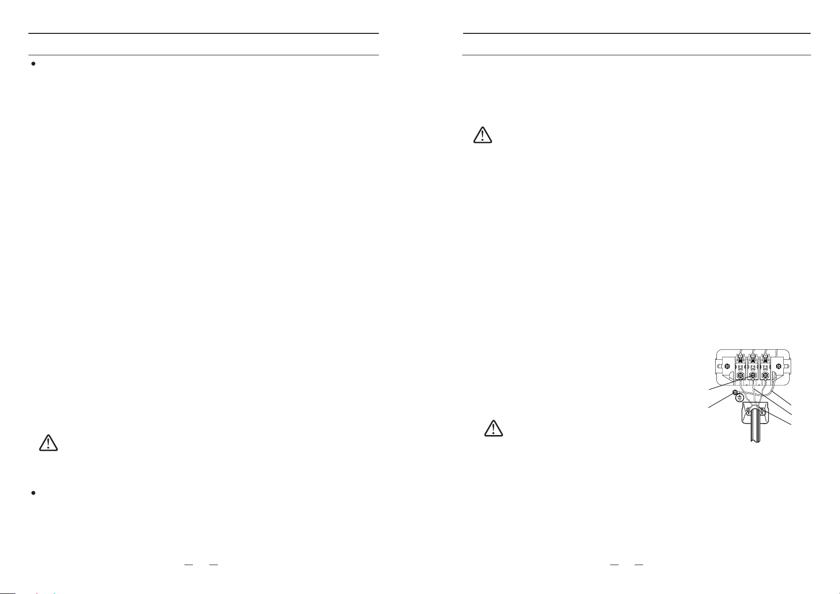
3-wire system instructions:
A.
external ground connector
C. Neutral grounding wire (White)
D. Neutral wire (white or center wire)
E. 3/4" (1.9cm) UL-listed strain relief
Center terminal block screw
B.
A
B
C
D
EIf converting from a 4-wire electrical system to a 3-wire,
the ground strap must be reconnected to the terminal block
support to ground the dryer frame to the neutral conductor.
WARNING
4-Wire system connections
1. Remove the center terminal block screw.
2. Connect the ground wire (green or unwrapped) of the power cord to the external
ground conductor screw.
3. Connect the neutral wire (white or center wire) of the power cord and the appliance
ground wire (white) under the center screw of the terminal block. Cross the screw
through the ring of wires’ terminal and tighten the screw.
4. Connect the other wires to the outer terminal block screws. Be sure to cross the
screw through the terminal ring and tighten the screw.
11
12
Loading ...
Loading ...
Loading ...