Loading ...
Loading ...
Loading ...
2. Run washer through one complete cycle to make sure it is op-
erating properly.
Vending
Meter Case
The factory mounted coin meter case does not include the service
door lock, coin slide (if applicable), coin drawer, coin drawer
lock or keys. These parts must be ordered (at extra cost) accord-
ing to the purchaser’s requirements direct from the manufacturer
of your choice.
NOTE: You have the option of using a screw type lock
or a 1/4 turn lock on the meter case service door. If you
choose to use a screw lock, then the special bracket
(located inside the meter case) must be used. DO NOT
use the special bracket if a 1/4 turn lock is used.
Coin Drawer Security - For additional security, drill out the two
pilot holes on each side of the front of the meter case to 1/4 or
5/16 inch [6.4 or 7.9 mm] holes and install a bicycle lock through
these holes.
NOTE: An 8 in. [203 mm] coin drawer is required for
coin operated electronic control models.
Models Prepped for Card Reader
The machine is shipped from the factory with the Electronic Con-
trol Diagnostic Harness Assembly unplugged. To avoid unauthor-
ized manual programming or vending, perform the following
steps.
1. Open control panel.
2. Locate diagnostic harness on electronic control.
3. Plug connectors for “white/black” wire and “blue/red” wire
together.
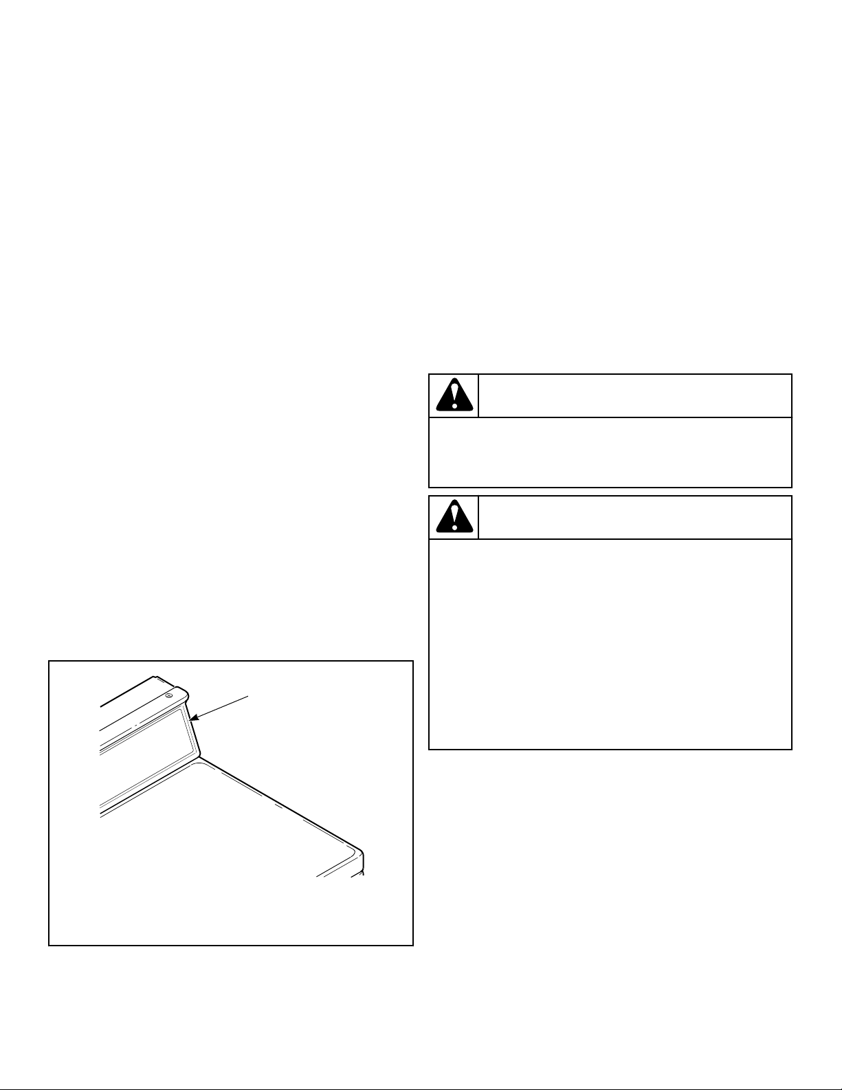
FLW6R_SVG
1
1. Control Panel
Figure 13
Additional Security
Located on the service door of meter case models is a flat Phillips
head screw. During shipment, this screw is used to attach the
service door to the meter case. For additional security, this screw
can be reinstalled inside the control hood of your unit. Refer to
instructions below for installation.
Tamper-resistant screws also can be installed for additional secur-
ity. Tamper-resistant screws, bits and bit holder are available as
optional equipment at extra cost. Part numbers are:
• Bit (No. 8 screws) Part No. 281P4
• Bit (No. 12 screws) Part No. 282P4
• Control panel tamper-resistant screw Part No. 35528
• Front panel tamper-resistant screw Part No. 35527
The following list is the procedure required to install the Phillips
head screw and tamper-resistant screws:
WARNING
Any disassembly requiring the use of tools must be
performed by a suitably qualified service person.
W299
WARNING
To reduce the risk of electric shock, fire, explosion,
serious injury or death:
• Disconnect electric power to the washer before
servicing.
• Never start the washer with any guards/panels re-
moved.
• Whenever earth/ground wires are removed during
servicing, these earth/ground wires must be re-
connected to ensure that the washer is properly
connected to a protective earth/ground.
W883
1. Remove the Phillips head screw from service door (refer to
Figure 14 ).
2. Remove two screws holding control panel to control hood.
3. Tilt control panel forward and lay on a protective pad to pre-
vent scratching of cabinet top.
4. Insert Phillips head screw down through double “D” hole in
left rear corner of cabinet top (inside control hood) until it en-
gages retainer nut located on left rear corner gusset of cabinet.
5. Finger tighten screw.
IMPORTANT: Do not use a power driver to tighten
screw. Torque of a power driver could over-tighten
screw causing damage to cabinet assembly.
6. Secure control panel to control hood using two No. 8 tamper-
resistant screws, Part No. 35528.
Installation
©
Copyright, Alliance Laundry Systems LLC -
DO NOT COPY or TRANSMIT
19 Part No. 205161EN
Loading ...
Loading ...
Loading ...