Loading ...
Loading ...
Loading ...
17
The extractor hood is designed to be mounted on
the wall.
•
During installation, optional accessories may
also require fitting.
•
Observe the minimum distance between hob
and extractor hood (see ”Safety instructions”)!
•
Avoid damaging the sensitive surfaces!
Preparing the wall
RISK OF INJURY,
DAMAGE TO PROPERTY
Before drilling the holes for the designated
installation location, check for concealed electrical
cables and other lines.
•
The wall must be level and vertical.
•
The enclosed screws and wall plugs are
suitable for solid brickwork. Use the
appropriate fixing materials for other wall
structures (e.g. plaster board, porous concrete,
poroton bricks).
Ensure that the wall has adequate load bearing
capacity.
•
Ensure that the depth of the drilled holes
corresponds with the length of the screws.
•
Ensure that the wall plugs are secure.
Max. weight: 88 lbs.
Design subject to modification in line with technical
development.
Note: At least one screw for the mounting must be
installed through a stud.
Installation preparations
1 Remove the grease filter (refer to Operating
Instructions).
2 Draw a line on the wall from the ceiling to the
lower edge of the hood at the centre of the
location where the hood is going to be
mounted.
3 Use the template to mark the points on the wall
where the screws will be mounted. In order to
make it easier to hook the hood onto the
screws, draw the outline of the area where the
hood will be attached.
Ensure that the minimum distance between the
hob and the extractor hood is maintained – 30” for
an electric hob and 30” for a gas hob. The bottom
edge of the template equates to the lower edge of
the extractor hood.
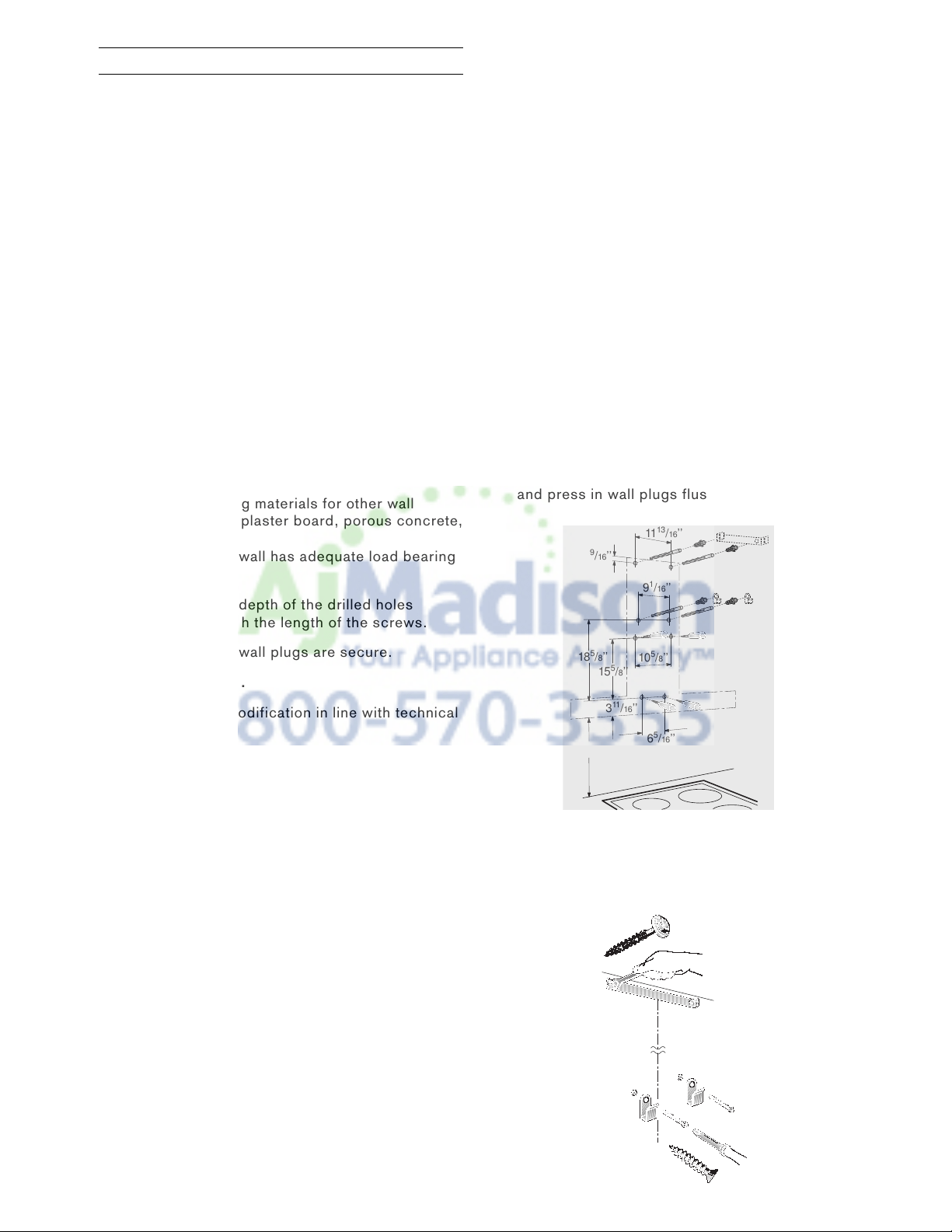
4 Drill 2x
5
/
16
” ø holes for the upper fixing bracket
and 2x
5
/
16
” ø holes for the lower fixing bracket
and press in wall plugs flush with the wall.
Note: Take into account any special accessories
that are going to be fitted.
5 Screw on the upper and the two lower fixing
brackets.
Installation
11
13
/
16
’’
9
1
/
16
’’
10
5
/
8
’’
6
5
/
16
’’
18
5
/
8
’’
30’’
15
5
/
8
’’
3
11
/
16
’’
9
/
16
’’
Loading ...
Loading ...
Loading ...