Loading ...
Loading ...
Loading ...
10
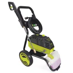
NOTE: The GFCI may need to be reset when rst plugged
into the electric outlet. Press the "Reset" button until
the power light indicator on the GFCI illuminates when
plugged in.
5. Turn the water supply tap on completely.
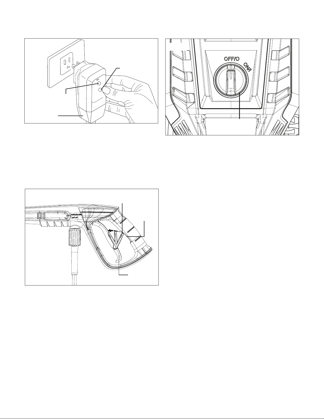
6. Make sure the safety lock is down and in its original
position (Fig. 15), then press the trigger for a few seconds
until water ow is steady. This will allow air to escape and
discharge any residual pressure in the hose.
7. Turn the ON/OFF switch to the ON/I position to start the
pressure washer (Fig. 16).
8. When re-starting the motor, always keep the
trigger pressed.
NOTE: The motor only runs when the trigger is operated
and shuts o when the trigger is released.
Using Nozzles
Before beginning any cleaning task, determine the best nozzle
for the job. Each of the nozzles has a dierent spray pattern.
The nozzle patterns are 40˚ (for gentle cleaning), 25˚
(for all-purpose cleaning), 15˚ (for tough jobs), 0˚ (for spot
cleaning or hard-to-reach areas), the soap nozzle (for detergent
application), and the turbo nozzle. The turbo nozzle is a
zero-degree rotary nozzle that spins the spray in a circle so it
has a wider cleaning swath.
mCAUTION! NEVER change nozzles without locking the
safety lock on the trigger handle.
mWARNING! High-pressure jets can be dangerous if
subject to misuse. The jet must not be directed at persons,
pets, live electrical equipment, or the appliance itself.
This electric pressure washer is equipped with six (6)
Quick-Connect nozzles that easily snap onto the
Quick-Connect collar of the spray wand (Fig. 17).
To connect a nozzle to the spray wand:
1. Turn o the pressure washer and shut o the water supply.
Pull the trigger to release water pressure.
2. Engage the safety lock on the trigger handle by pushing
up on the safety lock until it clicks into the slot (Fig. 17).
RESET
TEST
Fig. 14
GFCI
Power light
indicator
Reset
Fig. 15
Safety lock
Slot
Trigger
Fig. 16
ON/OFF
switch
Loading ...
Loading ...
Loading ...