Loading ...
Loading ...
Loading ...
85PO
SAVE THESE INSTRUCTIONS
(85PO) PRISM FRAME™ OVAL PREMIUM POOL ENGLISH 7.5” X 10.3” PANTONE 295U 05/13/2020
English
Page 11
5
11
9
8
POOL SETUP
(
continued
)
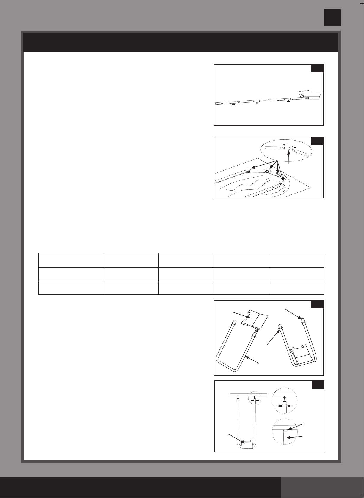
3. •
Be sure the liner is opened and spread out to its fullest
extentontopofthegroundcloth.Startingwithoneside,
slidethe“A”beamsfirstintothesleeveopeningslocated
ineachcorner.Continuewith“B”beamsnappingintothe
“A”beam,andanother“C”beamsnappingintothe“B”
beam
(see drawing 3
.
1)
.
Keepthemetalbeamholesalignedwiththewhiteliner
sleeveholes.
Continueinsertingall“A-B-C&D”beamsintothesleeve
openings.
•
Startthecornerjointcombinationforthepool’sshort
sides by inserting a corner joint
(6)
into“AorC”beam
first,thenslidea“D”beamintothesleeveopeningand
overthecornerjoint
(6)
. Continue inserting all the corner
jointsand“D”beams
(see drawing 3.2)
.(Besureall
4 sides end up with the metal beam holes aligned with
thewhitelinersleeveholes.)
•
The last joint connection may be difficult to complete.
You can do it though, if you first simultaneously raise
thelastjointandbeamabout2inches(5cm).Nowinsertthecornerjointintothebeamwhile
lowering the pieces into position. The corner joint will easily slide into the beam.
IMPORTANT: The eight corner joints are designed to be moveable relative to the horizontal
beams and not fixed to the horizontal beams. This allows the pool side walls to move inward
or outward when the pool is in use.
Thecombinationsforbeamsaredifferentfordifferentsizesofpools,seethechartbelowfordetail.
(Besureall4sidesendupwiththemetalbeamholesalignedwiththewhitelinersleeveholes.)
SizeofPool
No.of“U-shape”Leg
on longer side
No.of“U-shape”Leg
on shorter side
HorizontalBeam
Combinations on longer side
HorizontalBeam
Combinations on shorter side
16.5’x9’x48”
(503cmx274cmx122cm)
3 3 A-B-C D-D-D
20’x10’x48”
(610cmx305cmx122cm)
4 3 A-B-B-C D-D-D
4.
Slidetherestrainerstrap
(11)
onto the large U-shaped side
support
(9)
. Repeat for all restrainer straps and U-supports
(see drawing 4)
.
IMPORTANT: The liner is to remain flat on the ground
during the next step #5. This is why 5 - 6’ of clearance
space around the pool is necessary.
5.
ThetopsoftheU-shapedsidesupportshaveadouble
button spring loaded clip
(8)
that is factory pre-installed.
Insertthesidesupportsintothe“A-B-C&D”beamholes
bysqueezingthebottombuttoninwardwithyourfingers.
Squeezingthisbottombuttonwillallowthesupporttoenter
the beam. Once the U-support is inside the beam release
thefingerpressureallowingthesupportto“SNAP”into
place. Repeat this procedure for all U-shaped side supports
(see drawing 5)
.
4
11
7
8
9
(C)
(B)
(B)
(A)
3.1
3.2
6
Loading ...
Loading ...
Loading ...