LaView IP Camera User Guide
www.LaViewSecurity.com
0

LaView IP Camera User Guide
www.LaViewSecurity.com
1
Contents
1. INTRODUCTION
....................................................................
2
2. SAFETY INSTRUCTIONS
........................................................
2
3. INSTALLATION
.......................................................................
4
3.1 I
NSTALLATION OF
B
ULLET
C
AMERAS..................................
4
3.2 I
NSTALLATION OF
M
INI
D
OME
C
AMERAS...........................
6
3.3 I
NSTALLATION OF
V
ANDAL
-P
ROOF
D
OME
C
AMERAS.........
10
3.4 I
NSTALLATION OF
I
NDOOR
D
OME
C
AMERAS.....................
14
4. CONNECTING CABLES
.........................................................
17
5. LOGIN MENU SYSTEM
........................................................
18

LaView IP Camera User Guide
www.LaViewSecurity.com
2
1. Introduction
Thanks for purchasing our product. For any question or need, welcome
contact us at any time. We will make every effort to ensure correctness
of the information contained in this manual, which may be subject to
change from time to time without prior notice.
2. Safety Instructions
1) Please comply with the power supply specifications as required for
this equipment and select the correct power supply.
2) In case that the equipment fails to operate properly, immediately
contact the manufacturer or the nearest service center, instead of
disassembling or changing it in any way on your own.
3) For cleaning of the lens, be sure to use an air blower or dedicated
lens cleaner. For cleaning of the plastic shield, use a soft and dry
cloth to wipe it. Do not use any detergent containing alcohol or
benzene.
4) Do not drop any object onto the device or Knock heavy on the
equipment.
5) Do not put the camera toward any strong light source (or lighting
lamp or sun), which may cause over-exposure or light leakage (not
due to defect of the product) and impair useful life of the camera.
6) Avoid use of the equipment in any environment other than suggest
in this manual.
7) Prevent water or any other liquid from flowing into the equipment.
8) For replacement of any part, contact the distributor in advance and
make replacement with a new one , or similar components which
have the same specification. Change any part in the device
LaView IP Camera User Guide
www.LaViewSecurity.com
3
without authorization is not permit.
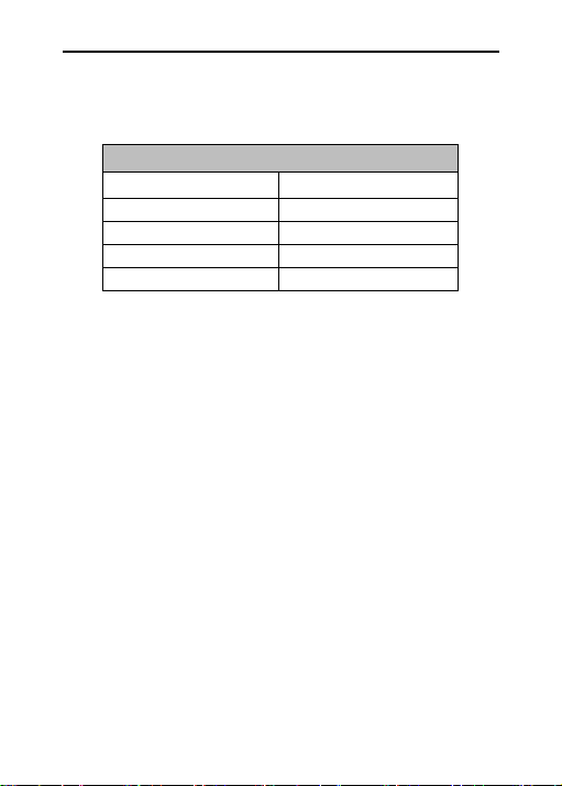
Operating Environment
Power Supply
DC12V±10%
Temperature
-30
℃
~60
℃
Humidity
10%~95%
Altitude
-60m~3000m
Atmosphere
86kpa~106kpa
LaView IP Camera User Guide
www.LaViewSecurity.com
4
3. Installation
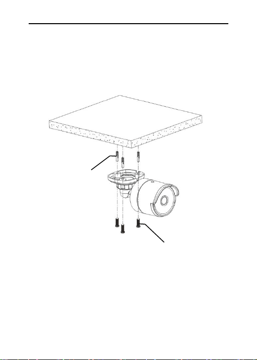
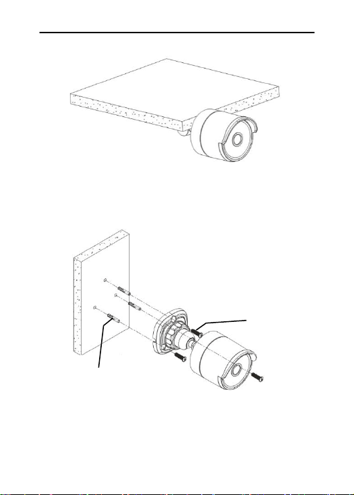
3.1 Installation of Bullet Cameras
a. Ceiling Mounting
Expansion Bolt
Locking Screw
Insert three expansion bolts in place into the ceiling and fix the equipment
with three locking screws.
LaView IP Camera User Guide
www.LaViewSecurity.com
5
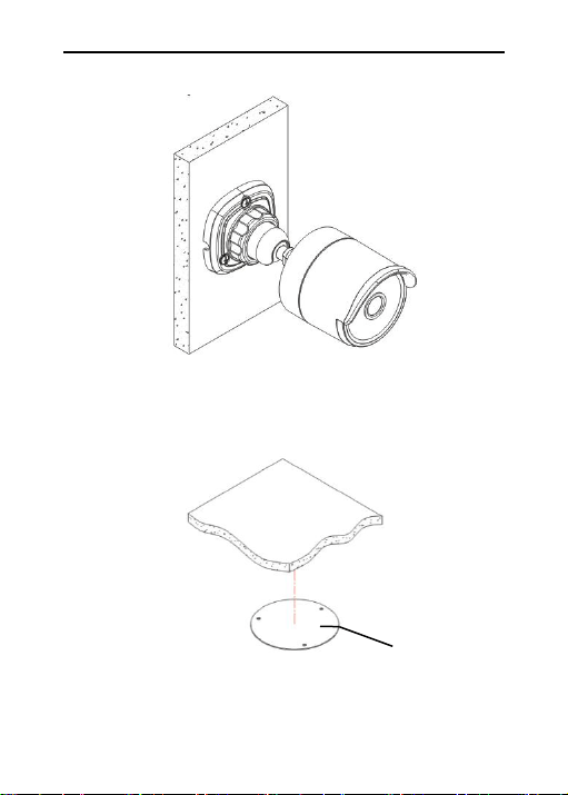
b. Wall Mounting
Completion of Installation
Insert three expansion bolts in place into the wall and fix the equipment
with three locking screws.
Expansion Bolt
Locking Screw
LaView IP Camera User Guide
www.LaViewSecurity.com
6
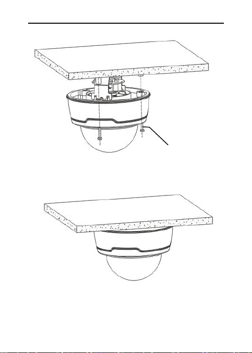
3.2 Installation of Mini Dome Cameras
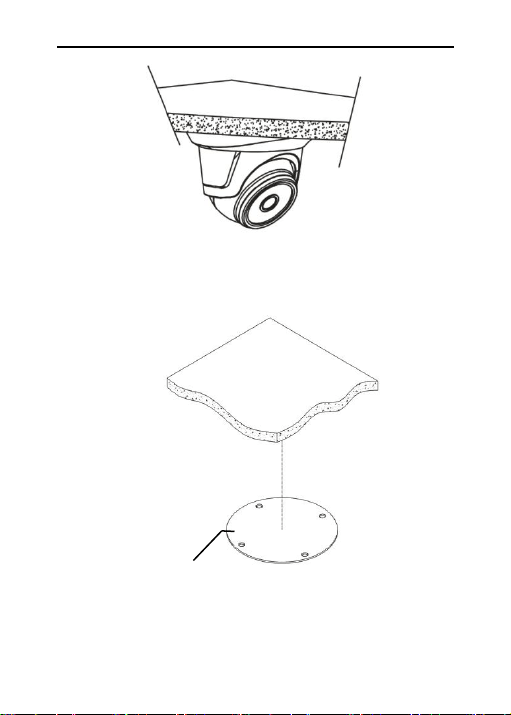
Ceiling Mounting
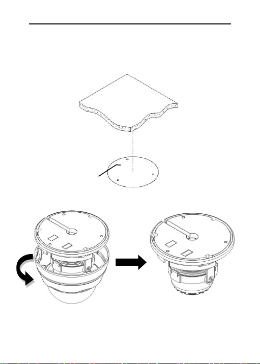
Paste the sticker in place at the proper position as selected.
Setup of Sticker
Completion of Installation
LaView IP Camera User Guide
www.LaViewSecurity.com
7
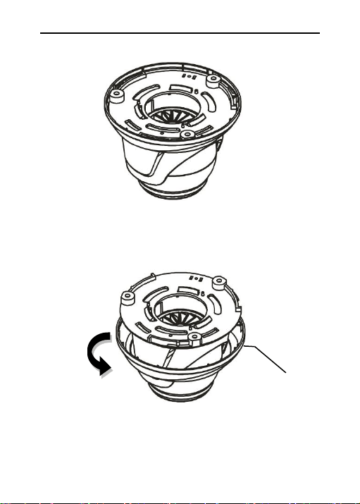
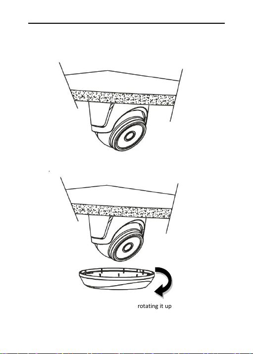
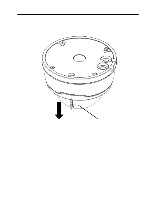
Mini Dome Camera
Collar
Remove the collar off the camera by rotating it down
LaView IP Camera User Guide
www.LaViewSecurity.com
8
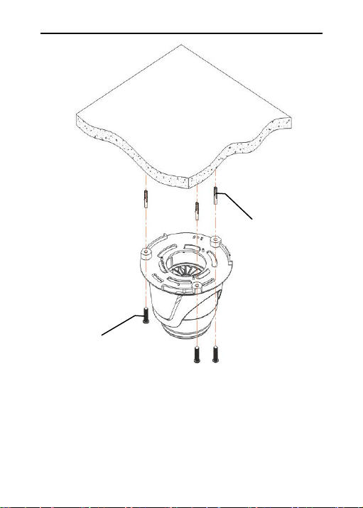
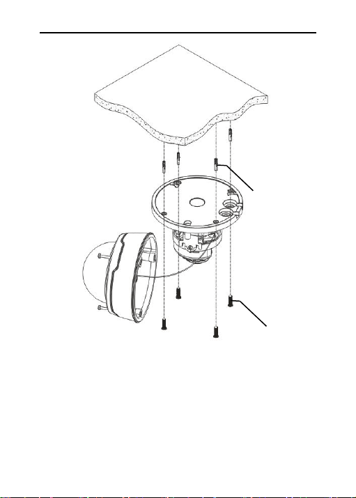
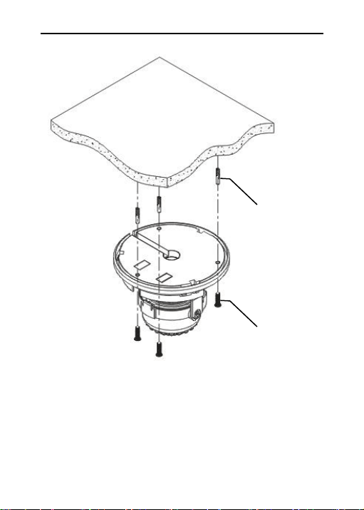
Fix the pedestal by drilling locking holes around the sticker and inserting
three expansion bolts into the holes and fastening it with three locking
screws.
Expansion Bolt
Locking Screw
LaView IP Camera User Guide
www.LaViewSecurity.com
9
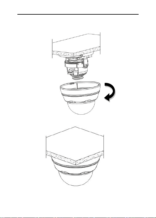
Mount the collar back by rotating it up
Adjust it to an appropriate angle.
LaView IP Camera User Guide
www.LaViewSecurity.com
10
3.3 Installation of Vandal-Proof Dome Cameras
Ceiling Mounting
Completion of Installation
Paste the sticker in place at the proper position as selected.
Setup of Sticker
LaView IP Camera User Guide
www.LaViewSecurity.com
11
Remove the front component by loosening the three locking
screws with a screwdriver.
Locking Screw
LaView IP Camera User Guide
www.LaViewSecurity.com
12
Fix the pedestal by drilling locking holes around the sticker and
inserting four expansion bolts into the holes and fastening it with
four locking screws. Adjust it to an appropriate angle.
Expansion Bolt
Locking Screw
LaView IP Camera User Guide
www.LaViewSecurity.com
13
Fix the front component on the pedestal by tightening the three locking
screws.
Completion of Installation
Locking Screw
LaView IP Camera User Guide
www.LaViewSecurity.com
14
3.4 Installation of Indoor Dome Cameras
Ceiling Mounting
Setup of Sticker
Paste the sticker in place at the proper position as selected.
Remove the shield off the camera by rotating the collar down
LaView IP Camera User Guide
www.LaViewSecurity.com
15
Expansion Bolt
Locking Screw
Fix the base by drilling locking holes around the sticker and inserting
three expansion bolts into the holes and fastening it with three locking
screws. Adjust it to an appropriate angle.
LaView IP Camera User Guide
www.LaViewSecurity.com
16
After angle adjustment, mount the shield back by rotating the collar
up.
Completion of Installation
LaView IP Camera User Guide
www.LaViewSecurity.com
17
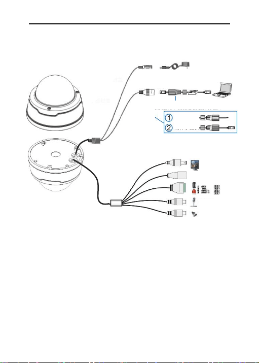
4. Connecting Cables
Note: Some model support POE function, after connect RJ45 cable, no
need to connect additional power supply .
Standard models only have basic functions.
full function models have all connectors.
Connection for Multiple Functions
Connection for Basic Functions
Reset Button
DC 12V Power
Client
10/100M Adaptable
Steps
Thread cable
Make crystal
head
BNC Output
Audio Input
Audio Output
Cable Waterproof structure, which must be
installed and tightened!

LaView IP Camera User Guide
www.LaViewSecurity.com
18
5. Login Menu System
1) Minimum system requirements:
CPU: Intel Core Duo II dual-core processor or higher
Memory: 1G or more
Video memory: 256M or more
Operating system: Windows 7/Windows 8/Windows 2008
(32/64-bit),
Windows 2003/Windows XP/Windows 2000 (only 32-bit)
Display: 1024 × 768 or higher resolution
IE: IE 6.0 or higher version
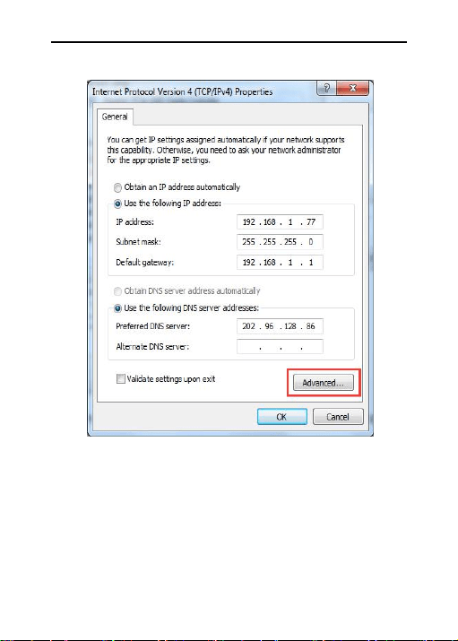
2) Network Connection Configuration
The default static IP address for the equipment is: 192.168.1.168
Procedure for Login Web interface:
LaView IP Camera User Guide
www.LaViewSecurity.com
19
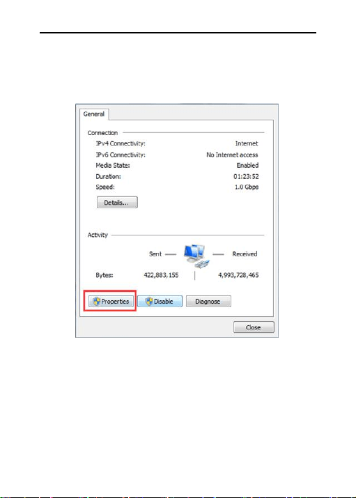
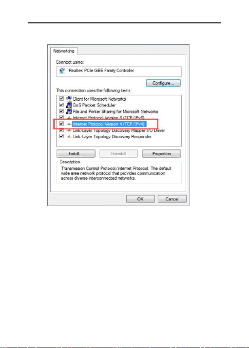
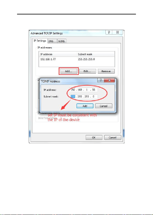
Step 1: Run to Control Panel > Network Connection and Sharing > Local
Connection in Windows 7 system, and set your PC in the same network
segment where the camera is located, as shown below.
LaView IP Camera User Guide
www.LaViewSecurity.com
20
LaView IP Camera User Guide
www.LaViewSecurity.com
21
LaView IP Camera User Guide
www.LaViewSecurity.com
22
Note: When software IPC Device Search is used for search, which employs
multicast protocol to search network information on the equipment across
segments, and no multicast data packet is permitted by any firewall, so a
firewall must be disabled to acquire network information on the
equipment.
LaView IP Camera User Guide
www.LaViewSecurity.com
23
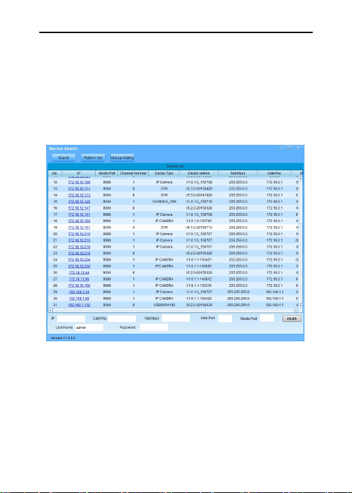
Step 2: Run the IP search tool Device Search provided in the CD as
attached.
Search IP address for the equipment within the segment by clicking Search
button. Any IP address acquired for the equipment and information on
HTTP port will be displayed as below.
Note: In case that access to IE by the equipment may fail due to IP address
conflict, the IP address has to be changed.
Changing procedure: Select the IP address to change > put down the
correct parameters > enter the password > click Change.
An example of correct parameters is given below: IP address:
192.168.1.123; Gateway: 192.168.1.1; Subnet mast: 255.255.255.0
Account name: admin; Password: admin
LaView IP Camera User Guide
www.LaViewSecurity.com
24
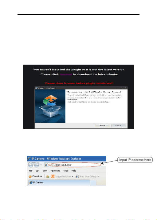
Step 3: For initial use of Internet Explorer (IE) for access to the network
camera, a plugin has to be installed by the following means:
Access IP address of the IP camera to automatically load the controls from
it.
In a pop-up plug-in installation dialog box, choose an installation option to
perform the installation process.
IPC Plugin
Step 4: Open IE and enter the IP address of the equipment in the address
bar and press ENTER.
LaView IP Camera User Guide
www.LaViewSecurity.com
25
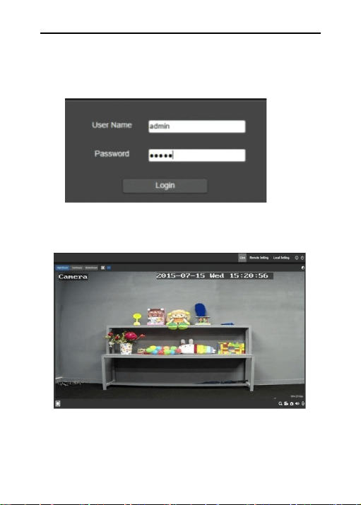
Step 5: Enter the user name and password (the default user name and
password are both "admin"), and click "Login" to log in.
Step 6: After successful login, The default preview page will be displayed.

LaView IP Camera User Guide
www.LaViewSecurity.com
26
