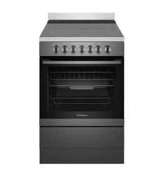
User manual Oven
DESCRIPTION OF YOUR APPLIANCE
INSTALLING THE APPLIANCE
(600mm wide product)
Cabinet requirements
This appliance has been designed to ‘slot-in’ to a 600mm wide gap built-in standard kitchen cabinets. As such the appliance can be installed to suit the height of the benches This allows the cooker to integrate well into contemporary kitchens. The cooker may also be installed at the end of a line of benches or with a free space on either side.
• Electric hob models must not be installed in a corner; they must be installed at least 100mm from the side wall. Gas hob models must be installed with a minimum clearance of 100mm to side walls made of unprotected combustible materials.
• For gas models refer to section 6.10.1 in AS/NZS 5601.1 for all relevant clearances.
WARNING
This appliance has been tested and approved to the relevant Australian Standards. It is designed to cook food, it will get hot. Cabinet materials must be capable of withstanding 85oC. Installation into lower temperature tolerant cabinetry (e.g. vinyl coated) may result in deterioration of the low temperature coating by discolour or bubbling.
Electrolux Home Products cannot accept responsibility for damage caused by installation into low temperature tolerant cabinets.
Installation and service warning
WARNING
- Only an authorised person must install and service this appliance (Certificate of Compliance to be retained).
- In order to avoid a hazard, the installation instructions MUST be followed.
- In order to avoid the appliance tipping, the anti-tilt plate MUST be installed.
- Appliances requiring connection to 230 – 240V MUST be earthed.
- An authorised person should inspect this appliance every 5 years.
- This appliance must NOT be installed on a base, box or in a closed cupboard.
- If the electrical supply cord is damaged, a qualified person MUST replace the cord to avoid a hazard or void your warranty.
- The unit must be pushed up against the wall on installation. On gas units check that the gas hose, if used, has not been kinked during installation.
Recommended cabinet design
-355412.png)
Preparing for installation
- Check that the required services are correctly positioned (see electrical and gas services requirements section and cabinet requirements section).
- Ensure that cabinetry has correct details (see cabinet requirements section).
- Unpack the cooker.
- Remove the foam pack containing accessories.
- Remove the internal pack from the oven and position shelf supports and grill trays.
- Remove the 2 screws for the splashback from the rear panel, and fit it to the unit with the same screws.
Following table outlines the distance between the floor supporting the product and the surface supporting cooking vessel:
-275304.png)
Fitting the anti-tilt plate & stabilising bolt
Cooker Stability
NOTE: To ensure cooker stability, both the anti-tilt plate and stability bolt MUST be installed on all cookers (electric and gas).
Installation Sequence
1. The cooker is delivered with the anti-tilt plate. Locate the anti-tilt plate against the rear wall. If locating between 2 cupboards, then fit the plate in the centre of the space. If locating the cooker at the end of a cupboard, then position the side of the plate 48mm from the cupboard.
NOTE: If cooker cannot be located against rear wall, move anti-tilt plate forward to suit.
-553651.png)
2. Securely fix the anti-tilt plate to the floor with appropriate fasteners.
3. Slide the cooker back into the anti-tilt plate so that rear cover rests against the rear wall. Then check the height and level of the cooker. If required, pull the cooker back out and adjust the levelling feet as required.
4. Cut the cable tie from the stability bolt.
5. Rotate the stability bolt 180 clockwise until it is pointing to the left like the picture below.
6. The stability bolt should now be able to drop to the floor.
7. Mark the position for the stability bolt on the floor.
8. Pull the cooker out and drill the bolt hole, using a 6.5mm masonry or wood drill. Minimum 30mm deep for concrete.
9. Reposition the cooker back into place, then fit the stability bolt into the drilled hole.
10. Connect gas and electricity supply (refer to pages following).
11. Fit the kick panel onto the cooker.
-792624.png)
Installing splashback
-641051.png)
INSTALLING THE APPLIANCE
(540mm wide product)
Cabinet Requirements
This appliance has been designed to ‘slot-in’ to a 550mm wide gap built-in standard kitchen cabinets. As such the appliance can be installed to suit the height and depth of benches and behind the kick rail of the cabinets. This allows the cooker to integrate well into contemporary kitchens. The cooker may also be installed at the end of a line of benches or with a free space on either side.
• Electric hob models must not be installed in a corner; they must be installed at least 100mm from the side wall. Gas hob models must be installed with a minimum clearance of 100mm to side walls made of unprotected combustible materials.
• For gas models refer to section 6.10.1 in AS/NZS 5601.1 for all relevant clearances.
-380499.png)
WARNING
In order to avoid accidental tipping of the appliance (for example, by a child climbing onto the open oven door), the anti-tilt plate and stabilising bolt MUST be installed.
-798791.png)
Position anti-tilt plate to the rear wall and 25mm from side of cupboard. Securely fix anti-tilt plate to the floor with fasteners. Adjust levelling feet on cooker as required.
Stabilising bolt
-106876.png)
Remove oven door - to be done by qualified personnel only. (Refer to procedure).
2. Remove screws from kick panel. To remove kick panel lift kick panel upwards to release the two location tabs from the holes in the bottom of the panel.
3. Position cooker into the ant-tilt plate and then mark the position for the stability bolt hole on the floor.
4. Pull cooker out and drill the bolt hole, using a 6.5mm masonry or wood drill bit. The bolt hole needs to be a minimum of 30mm deep when fixing the oven to concrete.
5. Reposition cooker back into place and fit the stability bolt through the slot and into the drilled hole.
6. If the cooker is placed on a base, measures must be taken to prevent the appliance slipping from the base.
WARNING For your safety this cooker is designed to be moved out of position by a qualified person only.
Installing Splashback
-353102.png)
WIRING REQUIREMENTS
The cooker MUST be installed in compliance with:
- Wiring connections in AS/NZS 3000 Wiring Rules
- Local regulations, municipal building codes and other statutory regulations
- For New Zealand Only:
The cooking range must be connected to the supply by a supply cord fitted with the appropriately rated plug that is compatible with the socket-outlet fitted to the final sub-circuit in the fixed wiring that is intended to supply this cooking range.
| Data plate |
gives information about rating |
| is located behind the bottom of the oven door |
• A functional switch operating in all active conductors MUST be provided near the appliance in an accessible position (AS/NZS 3000 - Clause 4.7.1).
• Wiring MUST be protected against mechanical failure (AS/NZS 3000 - Clause 3.9).
• Disconnection in the fixed wiring must occur in accordance with the AS/NZS 3000 wiring rules.
• The cooker MUST be properly earthed.
• This range must be connected with cable of 75°C rating minimum.
• This product has passed the insulation resistance test after manufacture. If the resistance reading is low at installation, it is probably caused by moisture from the atmosphere being absorbed by the elements after the range has been produced. (Pass at 0.01MΩ AS/NZS 3000 Wiring Rules Clause 8.3.6.3).
NOTE: When connections are made to a multi-phase 230/240V supply, the bridge piece MUST be removed from between the active connections.
TIPS AND INFORMATION
Before you cook in your new oven it is important that the protective oils used in the manufacture of the product be removed.
• Make sure that the room is well ventilated (to allow smoke to escape).
• New appliances can have an odour during first use. It is recommended to ‘run in’ the oven before cooking for the first time Operate the oven(s), empty, at a temperature of 180°C for approximately 30 minutes. For appliances with a separate grill, run the grill on maximum for 15 minutes WITH GRILL DOOR OPEN Please ensure that the room is well ventilated during this process.
-908871.png)
CONNECTING TO SERVICES AND COMMISSIONING
This appliance must be installed by an authorised person, according to all codes and regulations of:
• Electrical supply authorities.
• Building regulations.
• Local government and council authorities.
• AS/NZS 5601.1 (particular attention to clause 6.10.1, figure 6.3 and clause 6.10.1.11).
• AS/NZS 3000 (particular attention to clause 4.7.1 and clause 3.9).
Electrical supply connection
• WFE612, WFE616 and WFE512 models are fitted with a 20-Amp service cord.
• WFE614 and WFG612 models are fitted with a 10-Amp service cord.
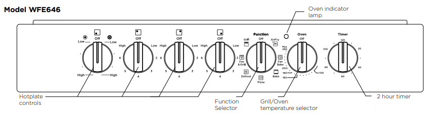
Hard wiring detail (WFE547, WFE646 and WFE647 models only)
1. Remove terminal cover plate from rear panel of appliance.
2. Fit wires through hole in cover plate and make connections to terminals.
3. Engage wires into plastic clip. Secure plastic clip with two long silver screws (supplied in separate bag).
4. Replace cover plate onto rear panel.
-7551.png)
RATED POWER INPUT
-778564.png)
CONNECTIONS
Wiring connection for gas cooker
To allow for disconnection of the appliance after installation, the plug must be accessible after installation.
If the supply cord is damaged, it must be replaced by the manufacturer, its service agent or similarly qualified persons in order to avoid a hazard.
Installing the gas cooker gas connection
Read these points before connecting to the gas supply:
• The cooker inlet connection point has a ½” BSP external thread. See diagram below.
• An NG regulator or a LPG/Propane test point fitting is supplied.
• It is recommended to fit the regulator or test point fitting to the appliance connection point, then fit either hard piping or a high level flexible connection (AS/NZS 5601.1 clauses 5.9 and 6.10.1.9) which is then attached to the consumer hard piping.
• Ensure installation allows withdrawal of appliance.
-290187.png)
Operation on universal LPG/propane
1. The appliance inlet fitting provided MUST be orientated so that the pressure nipple is accessible.
2. The inlet fitting has ½” BSP internal thread at the inlet and outlet.
Operation on SNG (WFG612 models only)
• If the cooker is to be used with SNG, then the grill burner MUST be modified by the replacement of the shutter, which fits into the throat of the grill burner.
• A conversion kit can be obtained by contacting the Customer Care Centre.
-285388.png)
-792846.png)
WARNING
Disconnect electric power before removing control panel.
1. Remove the control panel.
2. Remove the 2 screws from grill deflector (refer to diagram above)
3. Remove the existing NG shutter securing screw (refer to diagram above) and slide upwards to disengage from grill burner.
4. Slide the SNG shutter into position and secure with screws.
TESTING THE OPERATION OF THE GAS COOKER
NOTE: You MUST test the cooker after installation, before you hand it over to the customer.
You MUST have a manometer and a connecting tube
Checking gas supply
1. Check the manometer zero point is correct.
2. Connect the manometer to the cooker pressure test point. This is located on the regulator or LPG/ Propane inlet fitting.
3. Turn on the gas supply and the electricity and try to ignite the gas. NOTE: It will take additional time to light the gas for the first time as air needs to be purged from the pipes.
4. Check the operating pressure for the particular gas type. For details, see “Connections” on page 11.
NOTE: For LPG/Propane cookers: Adjust the regulator if necessary (this may be remote from the cooker).
For Natural Gas cookers
Regulators are supplied pre-adjusted and configured by the component maker for use with Natural Gas. The appliance installer is not required to make an adjustment to obtain the correct outlet pressure setting.
An arrow on the base of the regulator indicates the direction of gas flow when the inlet and outlet of the regulator are orientated correctly. When the regulator has been fitted check for leaks from the connections with soapy water.
Checking the Function of the Regulator
With the appliance operating check the outlet pressure:
• When all burners of the appliance are operating at maximum,
• When the smallest burner of the appliance is operating at minimum.
Under these conditions the outlet pressure should not vary from the nominal outlet pressure by more than ±20% of the nominal outlet pressure (ie ±0.20kPa for Natural Gas).
If the regulator appears to not be performing satisfactorily then check the following points.
1. If the outlet pressure is consistently too low then the inlet pressure may be too low and adjustment of an upstream regulator may be needed, or an upstream regulator or valve with insufficient flow capacity may be present in the gas supply line. If this is suspected then it may be necessary to repeat the checks whilst measuring both the inlet and outlet pressure to determine if the inlet pressure is in the range 1.13 – 5kPa.
2. Check that the regulator has been fitted to the gas supply line in the correct orientation, the arrow on the base of the body indicates the direction of gas flow.
Once these checks have been completed, if the regulator still fails to perform in a satisfactory manner it should be replaced.
Testing the cooker features
• Observe the flame appearance on each burner. If it is much smaller or larger than expected, then the injector size needs checking.
NOTE: When flame is unsatisfactory, then refer to the Electrolux Technical Publications and correct the fault, if possible.
When maximum flame appearance is correct, then check the turn-down setting on each burner. If the settings appear to be incorrect, proceed as follows:
1. Adjust the bypass screw mounted on the body of each hotplate control cock. This is accessible when the control knob is removed.
2. Check the ignition on all burners both separately and in combination.
3. Check the operation of the electrical components, if applicable.
4. If you are satisfied that the cooker is operating correctly, then turn it off and show the customer how to use it. Make sure you ask the customer to operate the controls.
NOTE: If the cooker cannot be adjusted to perform correctly, then inform the customer of the problem and put a warning notice on the cooker. If the problem is dangerous, then disconnect the cooker. If there is a fault, then the customer should be advised to contact the manufacturer’s local service organisation or the retaile
USING THE HOTPLATE
Hotplate dos and don’t’s
• Do not place heat resistant mats, wire mats or aluminium foil under pots and pans.
• Do not allow pots and pans to boil dry, as damage to both pan and hotplate may result.
• Do not use the hotplate as extra bench space or as a cutting board.
• Do not allow children on or near the cooktop at any time.
• Do not allow large cookware to overhang the hotplate onto the adjacent benchtop. This will cause scorching to the benchtop surface.
• Do not use round bottom woks or similar utensils which could lead to overheating of the hotplates and possible damage to the cooking surface.
• Use the stored heat in the hotplate by turning the control to off before the final few minutes of cooking.
• Do not slide pans across the surface of the ceramic glass as it could result in scratching of the surface.
Ceramic hotplates
The cooktop is made from ceramic glass, a tough, durable material that withstands heating and cooling without breaking. It is strong enough to hold the heaviest utensils. However, it must be remembered that as it is GLASS, it may break. Treat it accordingly!
Should you have any questions about the glass in your new appliance, please contact the service centre by dialling 13 13 49 (Australia) or 0800 436 245 (New Zealand).
-27253.png)
The heating elements are concealed under the smooth glass surface which has a pattern to show the location of the elements. When cooking, turn the control to the required setting.
The ceramic cooktop glass will retain heat for a period of time after the control is turned off. This will be indicated by the hot surface warning light which will continue to glow until the temperature drops below 60°C.
NOTE: If the ceramic glass is cracked switch off the appliance to avoid the possibility of electric shock
• Use pans with smooth, clean and dry bottoms to avoid scratching or burning residue into the glass.
• Ensure the pan bottom is the same size as the working element.
• We do not recommend ceramic glass pans because they do not conduct heat well.
• Stainless steel or enamelled saucepans are best.
• Do not use pans with copper or aluminium bottoms because they can leave traces which are difficult to remove from the glass.
• If buying new utensils select enamelled steel pans with 2-3mm thick bottoms or stainless steel pans with sandwich bottoms 4-6mm thick. The pan bottom should be flat, or preferably, slightly concave at room temperature so that it lies flat on the glass surface when hot.
-401503.png)
OPERATING FOR THE FIRST TIME
Choosing utensils for electric hotplates Refer to the diagram below.
-503248.png)
Choosing utensils for gas hotplates
Refer to the diagram below.
-494224.png)
Do not use utensils which are too large or too small.
Installation and service warning
WARNING
• Only an authorised person must install and service this appliance (Certificate of Compliance to be retained).
• In order to avoid a hazard, the installation instructions
MUST be followed.
• In order to avoid the appliance tipping, the anti-tilt plate MUST be installed.
• Appliances requiring connection to 230 – 240V MUST be earthed.
• An authorised person should inspect this appliance every 5 years.
• This appliance must NOT be installed on a base, box or in a closed cupboard.
• If the electrical supply cord is damaged, a qualified person MUST replace the cord to avoid a hazard.
USING THE GAS COOKER
Gas hotplate
Ensure burner caps, crowns and trivets are properly assembled.
-246447.png)
-595088.png)
Gas oven burner flame
From a cold start the oven burner flame will be higher on the left hand-side. After reaching the set temperature, the flame will become even. This does not affect cooking results.
-735011.png)
Lighting gas hotplate, grill and oven
Electronic ignition (For models WFE614, WFE612, WFE616 and WFE512)
These hobs are fitted with mains powered electronic ignition. When the appliance has been connected and the power is on, depressing any knob will release sparks to all burners. To light a burner, depress the corresponding knob and while continuing to depress knob turn anticlockwise to ‘HI’ position. The knob may be released once the flame is established, and turned further anticlockwise to reduce the flame height as desired.
Push button Ignition (For models WFG612)
Turn appropriate burner control knob to maximum and at the same time press the ignition switch.
Flame safeguard models (For models WFE614, WFE612, WFG612, WFE512)
Models with flame safeguard have the same ignition procedure as above but require the knob to continue to be depressed after flame is established for approximately 5 seconds. If the flame goes out when the knob is released, simply depress the knob again, this time holding it down with slightly more force for the same length of time.
Grill ignition (For models WFG612)
Turn Grill Control Knob onto maximum and at the same time press Electronic Ignition Switch. This burner also has flame failure, so it is required to depress the knob approximately 5 seconds after the flame is established. If the flame goes out when the knob is released, simply depress the knob again, this time holding it down with slightly more force for the same length of time.
Grill – in oven
Grill is electric and is operated by control knob only
Oven ignition – electronic (For model WFG612)
Push and hold Oven Control Knob onto desired temperature and at the same time press the Electronic Ignition Switch. Hold control knob in for 5 seconds after ignition.
Gas hotplates (Energy rating)
-516961.png)
1. Medium heat burner (9.0 MJ/h)
Used for normal cooking and simmering with mid size cookware items.
2. High heat burner (12.1 MJ/h)
Used for fast heating with large size cookware items.
3. Intense heat wok burner (14.2 MJ/h)
Used for very fast heating with woks and other large size cookware items.
4. Low heat burner (5.1 MJ/h)
Used for simmering and for use with small cookware items.
NOTE: Energy ratings above are for natural gas (NG) models.
To conserve gas, place the pan centrally over the burner and adjust the flame so that it does not go past the edge of the cookware.
NOTE: In the absence of electrical power, carry out the ignition directly to the burner with a hand held ignition source.
OPERATING THE 120 MINUTE MECHANICAL RINGER TIMER
(WHERE SUPPLIED)
Operating your 120 minute ringer timer
To set the timer, simply turn the knob clockwise to the required number of minutes.
Note: For any time below ten minutes, turn the knob past the thirty minute mark, then turn it back to the required number of minutes.
-285451.png)
USING THE OVEN
Fan baking
The temperature in the oven is controlled by a thermostat. The fan distributes the heat throughout the oven compartment. This allows:
- Baking on all shelves at the same time with little variation in browning or cooking.
- Cooking at slightly lower temperatures.
- Cooking from a cold start so there is no need to preheat the oven – this is good for casseroles and fruit cakes.
- Good cooking results for cream mixtures, rich pastries and bread but with these foods, preheating the oven for 10 to 15 minutes is required.
Defrosting
- Defrosting uses air that is circulated by the fan.
- You should defrost food before cooking it.
- You can also use the defrost function to raise yeast dough and dry fruit, vegetables and herbs.
Condensation
Condensation fogs the oven door and happens when you are cooking large quantities of food from a cold start. You can minimise condensation by:
- Keeping the amount of water used in cooking to a minimum;
- Making sure that the oven door is firmly closed;
- Cooking casseroles with a lid.
NOTE: If you are using water in cooking, this will turn to steam and may condense outside the oven. This is not a problem or a fault.
Cooking guide
- Select the correct shelf location for food being cooked.
- The grill tray can be used in the oven as a baking dish.
- Make sure dishes will fit into the oven and remove unnecessary trays or dishes before you switch it on.
- Keep edges of baking dishes at least 40mm from the side of the oven. This allows free circulation of heat and ensures even cooking.
- Do not open the oven door more than necessary.
- Do not place foods with a lot of liquid into the oven with other foods. This will cause food to steam and not brown.
- After the oven is turned off it retains the heat for some time. Use this heat to finish custards or to dry bread.
- Do not use a lot of cooking oil when roasting. This will prevent splattering oil on the sides of the oven and the oven door. Polyunsaturated fats can leave residue which is very difficult to remove.
- When cooking things which require a high heat from below (e.g. tarts), place the cooking dish on a scone tray in the desired shelf position.
- For sponges and cakes use aluminium, bright finished or non-stick utensils.
Oven shelf location
Your oven comes with formed “easy clean” runners that allow five positions for shelves These are numbered from 1 (the lowest shelf position) to 5 (the highest shelf position). See diagram.
To give maximum space above and below the shelves, load them in this way:
- When cooking with 1 shelf, use position 3.
- When cooking with 2 shelves, use positions 2 and 4.
-523519.png)
CLEANING THE COOKER
Ovens and hotplates are made from steel and enamel. Do not use abrasives and harsh scourers as they may scratch the surface.
Enamel
- Keep enamel clean by wiping it with a soft cloth dipped in warm soapy water.
- Rub difficult stains with a nylon scourer or cream powder cleanser.
- DO NOT use abrasive cleaners, powder cleaners, steel wool or wax polishes.
- If you use an oven cleaner, follow the instructions on the product carefully.
Stainless Steel
- All grades of stainless steel can stain, discolour or becomes greasy. Clean the cooker regularly, using the procedures outlined below, to maintain the function and appearance of your appliance.
- Care must be taken when wiping exposed stainless steel edges as they can be sharp.
- The front frame around the oven can be cleaned with stainless steel cleaners if it comes soiled or discoloured.
- A suitable cleaner can be purchased from Electrolux Customer Care Centres.
- Always clean the stainless steel in the direction of the grain. Going against the grain may scratch the surface.
Oven Shelves
- Chrome shelves: use detergent and hot water. If very dirty use a non-abrasive nylon scourer.
Oven – Grill Dish and Insert
- After every use and while still warm, wash pan and grill with warm soapy water and a suitable oven cleaner. Rinse and dry before replacing in position.
Oven
- Use detergent, warm water (and household cloudy ammonia if necessary) and a soft cloth. Dry thoroughly.
- Remove shelves when the cleaning oven.
- If there is a build-up of grease use a suitable oven cleaner, following the instructions on the cleaning product carefully. Heat oven to 110°C and turn oven off when 110°C is reached. Leave over-night. The fumes will loosen stubborn grease and stains. Remove bowl, wash with hot, soapy water and dry well before closing oven door again. Ensure oven is thoroughly rinsed and dried before subsequent use.
Glass
- Glass surfaces on doors and control panels are best cleaned immediately after soiling.
- A damp cloth may help remove baked on food deposits.
- Oven cleaners can be used to remove stubborn marks and stains.
WARNING
The door glass on this appliance is made from tough durable material that withstands heating and cooling without breaking. However it must be remembered that it is glass, it may break. Treat it accordingly!
Should you have any questions about the glass in your appliance, please contact the customer care centre by calling 13 13 49 (Australia) or 0800 436 245 (New Zealand). Do not use harsh cleaners or sharp metal scrapers to clean the oven door since they can scratch the surface, which may result in shattering of the glass.
Ceramic Hotplate
- Remove all spilt food and fat with the supplied razor blade scraper, while the ceramic glass is still warm but not hot. Wipe clean with dishwashing detergent on a damp cloth.
- If aluminium foil, plastic items or high sugar content foods are allowed to melt on the ceramic glass, clean immediately with the supplied razor blade scraper before the surface has cooled down, otherwise pitting of the surface can occur.
NOTE: Items with high sugar content not only include jam and fruit, but also vegetables such as peas, tomatoes and carrots.
- When the ceramic glass is cool, apply a suitable ceramic glass cleaner.
- It is important to follow the cleaner manufacturer’s instructions. Remove any cleaning residue from the surface as staining of the cooktop may occur.
- Do not use abrasive sponges or scourers, as they may scratch the surface.
- Any pitting, staining, scratches or other surface deterioration is excluded from the warranty.
- All stains/water marks can be removed by vigorous cleaning, using a ceramic glass cleaner.
- Sometimes surface stains appear to be ‘bubble’ marks under the ceramic glass. These can be cleaned with a razor blade scraper and ceramic cleaner.
Grill
- Always keep the grill tray and grill tray insert clean, as any fat deposits may catch fire.
Gas Burners
- Flame port blockages should be removed with a small metal cake skewer or nylon brush.
- Clean dirty spark plugs very gently with a nylon scourer. Do not use steel wool. Do not bend spark plug as it may break.
- If the caps, crowns and cups are heavily soiled, use a non-abrasive cleaning compound.
- Do not clean these parts with abrasive or caustic type cleaners, or clean in a dishwasher as they will be damaged.
Solid Hotplates
- Solid hotplates are fitted with stainless steel trim rings, which after initial use, change colour to light brown. This is a normal characteristic of stainless steel and will not affect the operation or performance of your hotplates.
- Clean off any spillage after hot plate has cooled down.
- At regular intervals, clean hotplate with a nylon scouring pad and soapy water. Wipe clean then warm hotplate for 30 seconds to dry the surface.
- Apply ‘hot plate protector’. Set hotplate on high for 3 minutes to allow coating to harden.
Cleaning the grill
Grill tray and grill pan
- Wash the grill tray and grill pan in hot soapy water.
Grill Compartment
- Clean the grill compartment with hot soapy water.
- If stronger action is needed use a non-abrasive oven cleaner applied with a nylon scourer.
Removing and replacing the oven light
WARNING Make sure the appliance is turned off before you remove or replace parts, to avoid the possibility of electric shock.
-368104.png)
A special high temperature resistant globe should be used. This can be purchased from the Electrolux Customer Care Centre. Light globes are not covered by warranty
CLEANING AND CARING FOR THE OVEN
Cleaning the oven door
Cool air circulates through the door to lower the surface temperature on the outside of the oven door.
CAUTION
• Do not remove the outer oven door. This product has a removable inner glass insert for ease of cleaning.
To remove the inner door glass for cleaning
• Open the door fully to access the hinges then rotate the “stirrups” on both hinges fully towards the door
-295832.png)
• Slowly close the door until it stops against the ‘stirrups’.
-962288.png)
• To remove the top cap, press the ribbed release clips at each end and lift top cap away from the door.
-991293.png)
• Using both hands, gently remove the inner glass by sliding out and lifting away from the door.
-921835.png)
• Hand wash only with a soft cloth and warm soapy water. When dry, polish with a soft cloth and ensure the glass is dry before re-assembly.
• Wipe inner and outer glass gently with detergent and warm water.
• Wipe clean and dry thoroughly
Re-assembling the oven door inner glass
- When replacing the door inner glass, make sure the circle is positioned as shown in the image (where applicable).
- Replace the top cap ensuring the clips snap back into position.
- Fully open the door, rotate the stirrups back to their original position and close the door.
Door glass
- DO NOT use harsh abrasive cleaners or sharp metal scrapers to clean glass since they can scratch the surface, which may result in shattering of the glass.
SOLVING PROBLEMS
Faults
If there is a problem with the oven and/or grill, please:
• Check the points listed below before calling for service. It may be possible to avoid a call by fixing the problem yourself – and so continue cooking.
• For cooking problems, refer to “Dealing with cooking problems”.
NOTE: We may charge for service even in the guarantee period if your problem is due to the causes listed below.
Further information
If you need more information, service, replacement parts or have a warranty enquiry, please contact the Customer Care Centre:
• Australia – 13 13 49, 8.00am - 5.00pm EST Monday - Friday
• New Zealand – 0800 436 245, 8.00am - 5.00pm EST Monday - Friday
Please have the following information ready: Model, Model Number and Serial Number. This is shown on the data plate which is visible when the oven door is open.
|
PROBLEM
|
POSSIBLE CAUSES
|
WHAT TO DO
|
| Oven or grill not working |
Power not turned on
Household fuse blown
Controls incorrectly set
Circuit breaker tripped
Clock not set
Gas is off
|
Switch on electricity
Check fuses
Reset controls
Check circuit breaker
Set time of day on timer
Check gas is supplied to the cooker
|
| NOTE: If the household fuse continues to blow, call the Electrolux Customer Care Centre. |
| Oven not heating enough |
Foil or trays on bottom of oven Oven not pre-heated. |
Remove foil or trays Pre-heat oven for 30 minutes |
| Light and fans on continuously |
Timer not in manual mode |
Set timer to manual mode |
| Oven not working |
Timer not in manual mode Household fuse blown |
Set timer to manual mode Check fuses |
| NOTE: If the household fuse continues to blow, call the Electrolux Customer Care Centre. |
| Oven light not working |
Household fuse blown
Circuit breaker tripped
Lamp blown or loose in socket
|
Check fuses
Check circuit breaker
Replace or tiqhten lamp
|
| NOTE: If the household fuse continues to blow, call the Electrolux Customer Care Centre. |
| Cooker smoking when first used |
Protective oils being removed |
Turn grill on high for 30 mins and then the oven on 220°C for 1 hour |
| Too much condensation building up when baking |
Too much water used when cooking |
Reduce amount of water |
| Leave oven door open after cooking |
| Smells when first using oven |
Protective oils being removed |
This is normal |
| 120 minute timer ring not audible |
Timer not wound sufficiently |
Turn timer knob past 20 minutes then turn back to required number of minutes |
| Gas hotplates not working |
Power not turned on at appliance Household fuse has blown or power supply is turned off Gas is off
Burner parts or spark plugs are wet or dirty
|
Switch on electricity Check fuses
Check gas is supplied to the cooker Clean and dry burners or spark plugs
|
| Timer flashing |
Power failure or interruption |
Reset time of day |
| Stains appear to be under ceramic glass |
These marks are on the surface of the ceramic glass. |
Clean marks off with a razor blade scraper and ceramic glass cleaner. |
| The oven seal is loose |
The oven seal is attached at each corner. It may seem like a loose fit. but when the oven door is closed it will function correctly. |
This is normal |
NOTE: In the event of a power failure the gas burners may still be lit with a handheld igniter and used. Take care to avoid letting unburned gas flow for more than 5 seconds when attempting to light the burner.