Loading ...
Loading ...
Loading ...
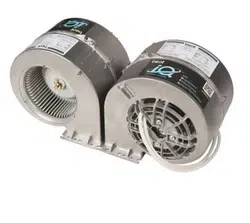
MODEL iQ12
Page 4
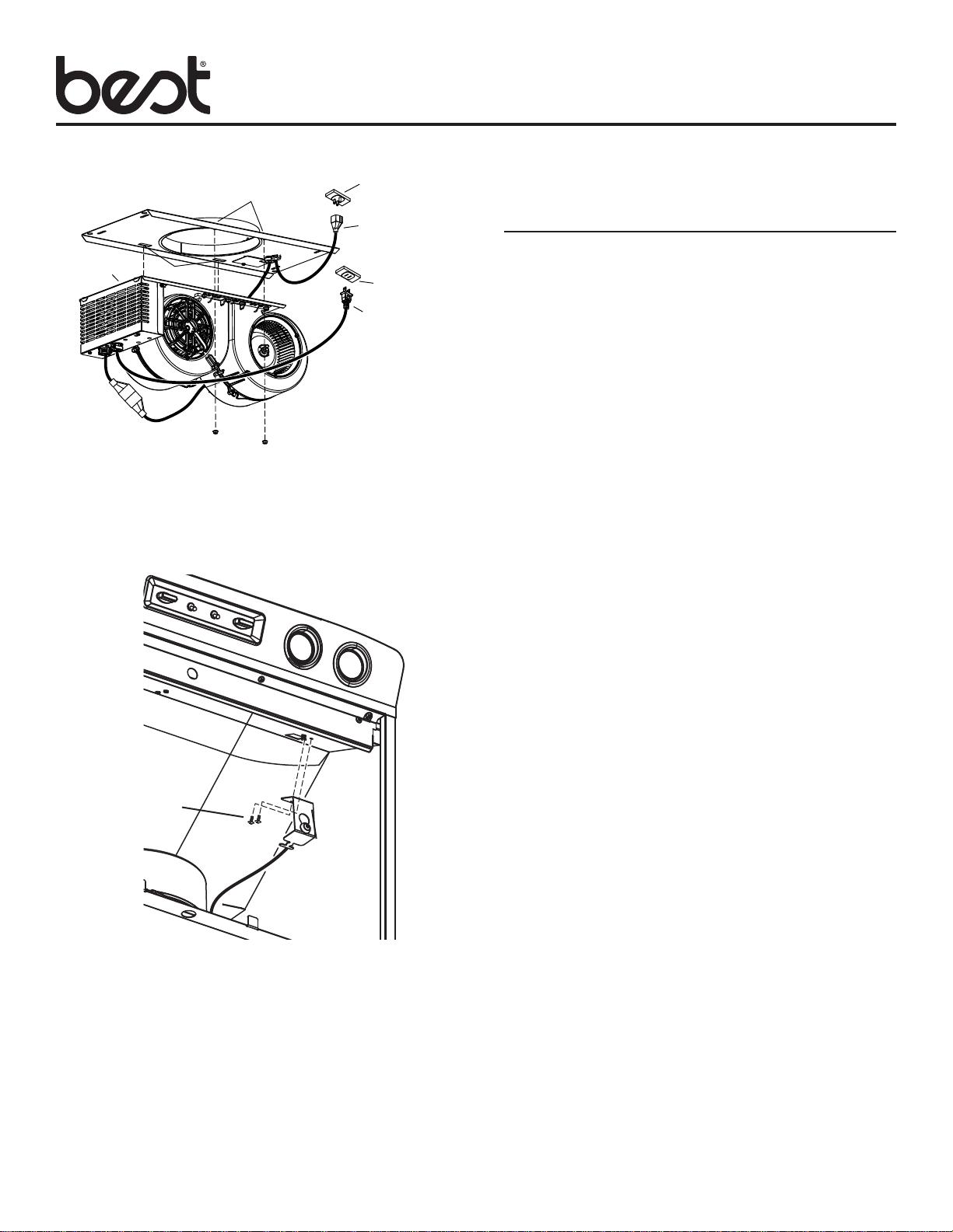
7. Engage two TABS on BLOWER / MOUNTING PLATE AS-
SEMBLY into two SLOTS in ROUGH-IN PLATE. Secure
blower / mounting plate assembly to THREADED STUDS
on rough-in plate with (2) 10-24 HEX NUTS.
Ducted Internal Blower Hoods Only
After the blower is installed and wired, engage the calibration
process (our Guaranteed Performance System Technology) to
ensure full-rated airflow is being delivered. Prior to calibration,
ensure that all light bulbs and duct system components are
installed and sealed.
CALIBRATION PROCESS
Hold the calibration button for 3 seconds; calibration button
will light up and stay on for up to 13 minutes. Install filters and
wait for blower to start which signals the start of the calibration
process. When calibration is complete, one of two things will
occur:
A. The blower turns off and calibration button light turns off =
Successful calibration.
B. The blower turns off and calibration button light blinks
continuously = Too much restriction in the ductwork is
preventing the IQ Blower System
TM
from achieving the
rated airflow. The blower is automatically set to maximum
intensity.
NOTE: Common items that cause restrictions: restricted
damper flap (backdraft damper, wall cap, roof cap), too many
elbows, duct size less than 80% of hood outlet, poor transition,
use of flex ducting and/or crushed ducting.
Two options are available:
1. Press the calibration button to accept airflow as is. The IQ
Blower System
TM
is now configured to its highest possible
setting. The blinking calibration light goes out.
2. Correct duct restriction and repeat the calibration process.
a. To clear the original calibration data, hold calibration
button for 10 seconds. The light will blink 3 times to
confirm and the blower configuration will go back to
default settings.
b. Repeat calibration process.
CALIBRATE iQ BLOWER
SYSTEM
BLOWER /
MOUNTING
PLATE
ASSEMBLY
ROUGH-IN
PLATE
SLOTS
STUDS
ROUGH-IN
PLATE
POWER
CORD
BLOWER
POWER
CORD
TABS ON
BACK EDGE
OF PLATE
HEX NUTS (2)
HOOD
RECEPTACLE
HOOD
RECEPTACLE
8. Install the CALIBRATION BUTTON ASSEMBLY using (2)
SCREWS (provided).
9. Plug one of the rough-in plate power cords into the control
box power cord.
10. Plug BLOWER POWER CORD and ROUGH-IN PLATE
POWER CORD into HOOD RECEPTACLES.
11. Wrap excess wires with wire ties (provided) to prevent contact
with blower wheel.
CALIBRATION
BUTTON
ASSEMBLY
(2) SCREWS
Loading ...
Loading ...
Loading ...