Loading ...
Loading ...
Loading ...
ASSEMBLE SURFACE BURNERS (CONT.)
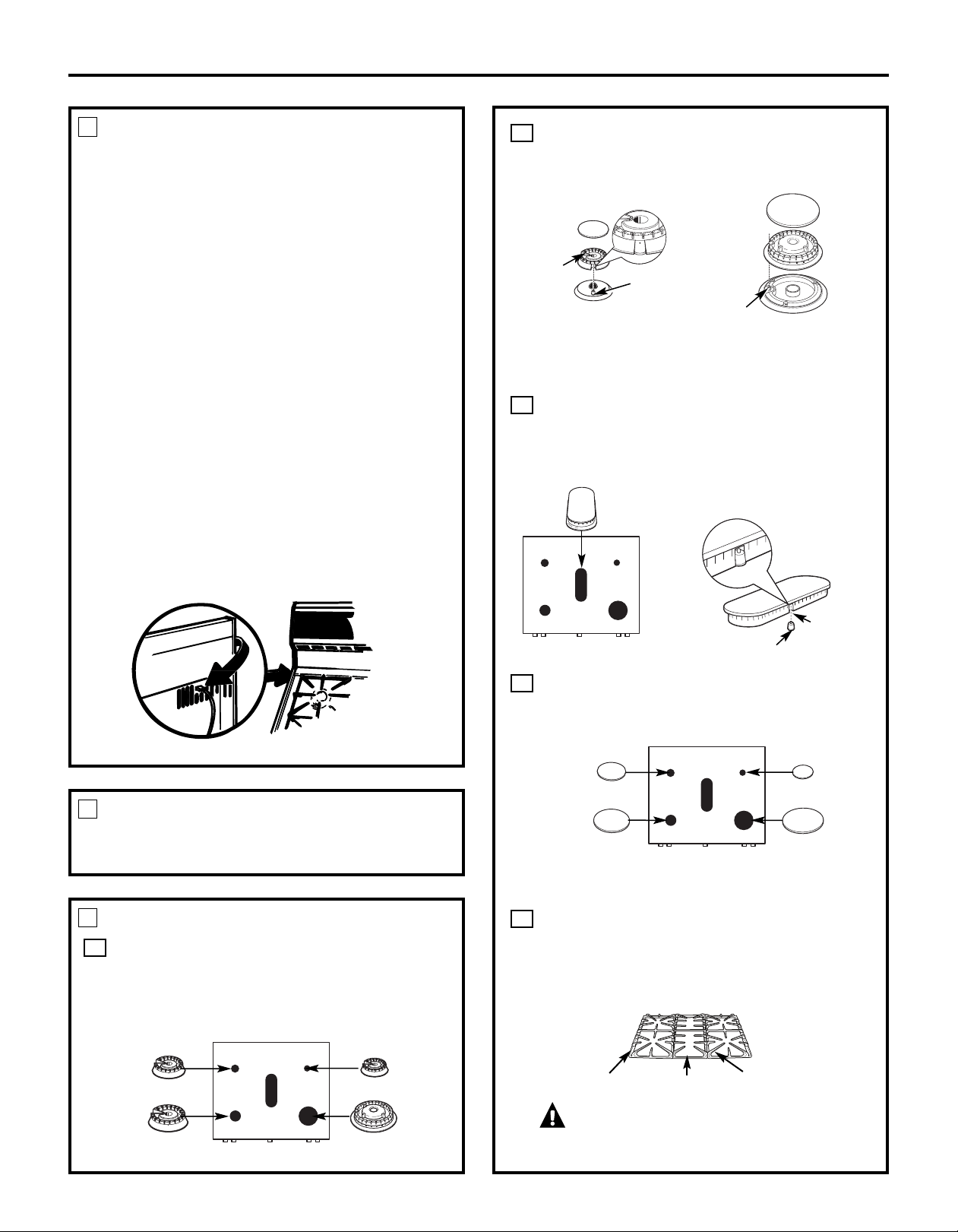
Oval (Center) Burner Head/Cap Assembly
Place the oval (center) head/cap assembly over the
electrode on the cooktop.
Caps
Place the matching size caps onto the burner bases
or heads.
Make sure that the heads and caps are replaced in the
correct locations.
Grates
Place the side and center grates on the cooktop. These
grates are position specific. The undersides of the side
grates are marked “OUTSIDE.” The center grate can be
interchanged front to back.
CAUTION: Do not operate the burner
without all burner parts in place.
D
C
B
5
Installation Instructions
ELECTRICAL CONNECTIONS (CONT.)
3
B. Usage Situations where Appliance Power Cord will
be Disconnected Frequently.
Do not use an adapter plug in these situations because
disconnecting of the power cord places undue strain on
the adapter and leads to eventual failure of the adapter
g
round terminal. The customer should have the two-
prong wall receptacle replaced with a three-prong
(grounding) receptacle by a qualified electrician
before using the appliance.
The installation of appliances designed for mobile home
installation must conform with the Manufactured Home
Construction and Safety Standard, Title 24 CFR, Part 3280
(formerly the Federal Standard for Mobile Home
Construction and Safety, Title 24, HUD, Part 280) or,
when such standard is not applicable, the Standard
for Manufactured Home Installations, latest edition
(Manufactured Home Sites, Communities and Set-Ups),
ANSI A225.1, latest edition, or with local codes. In Canada,
mobile home installation must be in accordance with the
current CAN/CSA Z240/MH Mobile Home Installation Code.
Electric Disconnect
■ Locate disconnect plug on the range back.
■ Pinch sides of connector and pull out of range back.
SEAL THE OPENINGS
4
Seal any openings in the wall behind the range and in the
floor under the range when hookups are completed.
ASSEMBLE SURFACE BURNERS
5
Burner Heads
Place burner heads over the electrodes on the cooktop,
in the correct locations according to their size. There is
one small, one medium, one extra large and one dual
flame extra large burner head.
A
Medium head
Front of range
Extra large head
Small head
Dual flame
extra large head
47
Electrode
Slot
Front of range
Oval head and cap
assembly
Medium cap
Front of range
Extra large cap
Small cap
Dual flame extra
large cap
Make sure the slot in the burner
head is positioned over the
electrode.
Outside grate
Outside grate
Center grate
Burner cap
Burner
head
Burner base
Electrode
Burner cap
Burner
head
Burner
base
Electrode
Stability
chamber
Make sure the slot in the
burner head is positioned
over the electrode.
Make sure the hole in the burner head
assembly is positioned over the electrode
and that the burner head is fully inserted inside
the burner base. A small gap between the base
and head is normal.
Front left, back right and back left burners
Front right burner
Loading ...
Loading ...
Loading ...